MSEC 2014_microstructural analysis and nanoindentation characterization of ti 6-al-4v parts from electron beam additive manufacturing
•
0 likes•224 views

Recommended

Recommended
More Related Content
What's hot
What's hot (20)
Similar to MSEC 2014_microstructural analysis and nanoindentation characterization of ti 6-al-4v parts from electron beam additive manufacturing
Similar to MSEC 2014_microstructural analysis and nanoindentation characterization of ti 6-al-4v parts from electron beam additive manufacturing (20)
Recently uploaded
Recently uploaded (20)
MSEC 2014_microstructural analysis and nanoindentation characterization of ti 6-al-4v parts from electron beam additive manufacturing
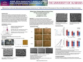
- 1. INTRODUCTION Additive manufacturing (AM) is an emerging technology based on “layer-by-layer” fabrications. AM technology offers many design and manufacturing advantages such as short lead time, complex geometry capability and tooling free. Electron beam additive manufacturing (EBAM) is a type of AM technology for the direct manufacturing of metal products by melting metallic powders. EBAM utilizes a high-energy electron beam, as a moving heat source, to melt and fuse metal powders and produce parts in a layer-building fashion. It is of great interest to investigate the possible build heights effects on microstructure and mechanical properties. Ti-6Al-4V is the most common titanium alloy used in such industries, the application of EBAM on Ti-6Al-4V achieves the fine structure and superior mechanical properties. EXPERIMENTAL DETAILS Sample Fabrication Microstructural Characterization Optical Microscope (OM), Scanning Electron Microscope (SEM) Nanoindentation Triboindenter: Berkovich tip (radius of 100 nm, included angle of 142.3 deg.) POWDERS CHARACTERIATION Raw Powders: a diameter between 45 and 100 µm Sintered Powders: connected powders MICROSTRUCTURES Side Surfaces (X-plane) Top layers: straight and fine columnar prior β structure Middle layers: curved columnar structure Bottom layers: martensitic structure Scanning Surface (Z-plane): equiaxed grains and Widmanstätten (α+β) General Structure: rod-shaped NANOINDENTATION CONCLUSIONS (1) The side surfaces specimens show columnar prior β grains with martensitic structures. The top layers presents the smallest columnar width. (2) The scanning surfaces show equiaxed grains. The inside microstructure consists of fine Widmanstätten (α+β) and α′ martensites. (3) The highest elastic modulus and hardness are located at the scanning surface of the top layers. In addition, the elastic modulus and hardness are higher on the scanning surface than those from the side surface. ACKNOWLEDGEMENTS The materials presented in this paper are supported by NASA, under award No. NNX11AM11A. XG also acknowledges the AL EPSCoR GRSP for the financial support. MICROSTRUCTURES AND NANOINDENTATION CHARACTERIZATION OF TI-6AL-4V PARTS PROCESSED BY ELECTRON BEAM ADDITIVE MANUFACTURING ABSTRACT: The microstructure analysis and nanoindentation characterization were conducted to study the Ti-6Al-4V parts processed by electron beam additive manufacturing. The effect of build height on the microstructural evolution and mechanical properties was investigated. Columnar prior β grains are shown on the side surface and equiaxed grains are presented on the scanning surface. The top layers present finer columnar structure, while the bottom layers show bigger percentage of α′ martensites owing to the high cooling rate. Nanoindentation tests identify the highest elastic modulus of 127.9 GPa and hardness of 6.5 GPa. Xibing Gong, Xiaoqing Wang and Kevin Chou Mechanical Engineering Department The University of Alabama Tuscaloosa, AL 35487 xgong2@crimson.ua.edu ASME Poster MSEC2014-4216 Fig. 1 Configuration of EBAM machine Application: Aerospace, Military, Biomedical; Complex/Unique Geometry/Structure; Customized, Small Batch. Advantages: Metal, Alloy, Intermetallic alloys; High Scan Rate; Fine Microstructure; Lower Residual Stress. Challenges: Accuracy, Surface Finish, Powder Variation, Process Sensitivity, and Process Monitoring. Fig. 2 Nanoindentation setup Fig. 3 Load vs. time Fig. 11 Test samples Fig. 5 Raw powders Fig. 6 Sintered powders X-plane Z-plane Top Middle Bottom Fig. 7 OM of samples with different build heights Top Middle Bottom Fig. 8 SEM of samples with different build heights Fig. 9 SEM of lamella α of parallel bundles with very small amounts of β in the α boundaries Fig. 10 Microstructure of mixed α′, α and β due to high cooling rate during solidification 127.09 120.06 122.12118.71 114.2 117.57 100 105 110 115 120 125 130 135 140 Top Middle Bottom ElasticModulus(GPa) Z-Plane X-Plane 4.97 5.84 3.47 3.29 4.17 3.14 6.47 6.09 6.225.6 5.75 5.86 2 3 4 5 6 7 8 Top Middle Bottom Hardness(GPa) Z-Plane X-Plane 0.41 0.51 3.14 0.29 0.31 0.33 Fig. 4 Indent pattern Fig. 12 Force-displacement Fig. 13 Elastic modulus Fig. 14 Hardness