1. The International Journal Of Engineering And Science (IJES)
|| Volume || 3 || Issue || 11 || Pages || PP -10-17 || 2014 ||
ISSN (e): 2319 – 1813 ISSN (p): 2319 – 1805
www.theijes.com The IJES Page 10
Effects of Various Material Infiltrants in Sls Process
J.Saiganesh 1
,J.D.Andrew Pon Abraham 2
1,2
Assistant Professor ,Department of Automobile engineering Kumaraguru College of Technology
Coimbatore, India
--------------------------------------------------- ABSTRACT -----------------------------------------------------
This paper presents the infiltration effect of various materials produced by selective laser sintered stainless steel
green parts. Quality of the rapid prototyping products are decided by the various factors such as process type,
type of infiltration, layer thickness, orientation, laser speed etc.,. The infiltration effect of Bell Metal, Brass, and
Bronze on stainless steel green part was determined. Hardness, dimensional study bending strength and surface
roughness are determined.
Keywords: Infiltration, layer thickness, orientation, laser speed
---------------------------------------------------------------------------------------------------------------------------
Date of Submission: 05 November 2014 Date of Accepted: 15 November 2014
---------------------------------------------------------------------------------------------------------------------------
I. INTRODUCTION
Freeform fabrication of metallic parts poses unique challenges. Because metals have high melting point,
are classically brittle and are resistant to powder sintering, the processes for their manufacture are limited in
general. Posing additional manufacturing constraints associated with freeform fabrication exacerbate the
problem of part creation. Therefore, direct free forming has not been feasible. However, an indirect freeform
fabrication approach has proven viable, involving free forming a green part with the assistance of a binder
followed by post-processing to produce a final part. One potential post-processing approach involves infiltration
of a free formed metallic green part with a lower melting point phase such as an epoxy or metal. Infiltration
offers several manufacturing advantages for free formed metallic parts. Infiltration is applicable for parts with
open or continuous porosity which serves as a pathway for the infiltrant into the part. This allows relatively
rapid full density processing. Dimensional changes, the primary subject of this paper, are minimal as the rigid
part framework does not change shape significantly during infiltration. Commercially available freeform
machines used for green part creation do not require prior modification since the binder is a low-melting-point,
fusible material.
II. RAPID PROTOTYPING
RP is a generic term for a number of technologies that enable components to be made without the need
for conventional tooling in the first instance or indeed without the need to engage the services of skilled model-
makers. Many manufacturing processes are subtractive, in that they modify the geometry of a mass of material
by removing parts of the material until the final shape is achieved. Conventional milling and turning are good
examples of subtractive processes. By contrast, RP techniques are additive processes. RP components are built-
up gradually in layers until the final geometry is obtained. The way in which the layers are produced, however,
and the materials in which parts can be built vary significantly between the different RP processes.
The starting point for the RP process is typically a 3D CAD model prepared and exported to meet the
requirements of a given technology. Various other “inputs”, in addition to CAD, can be used to create RP
components; these include medical applications such as MRI and CAT scanning as well as point cloud data
generated by engineering scanning or digitising systems. Whatever be the source of the original data it is
reformatted into a stl file and sliced horizontally, each individual slice is subsequently presented to the selected
RP manufacturing process. The RP system will subsequently reproduce the sliced data thereby creating a
physical example of the original “CAD” data.
III. THREE STAGES OF RP SYSTEM
Although there are several RP technologies with different working principles, they all produce parts
using similar steps:
2. Effects Of Various Material …
www.theijes.com The IJES Page 11
A three-dimensional CAD file is “sliced” into two-dimensional contours, representing cross-sectional
layers of the object
This information is sent to a RP machine, where the build plan is generated
Starting with the bottom layer, a cross-section of the part is deposited (usually via the rastering of the
2D contour with several line deposits)
The part is lowered one layer thickness (typically via a build elevator), and the next layer is deposited;
this process repeats until the entire part is deposited.
Three Stages of RP System
IV. SELECTIVE LASER SINTERING
Selective Laser Sintering (SLS) is well-known technique for rapid proto-typing, rapid manufacturing
and rapid tooling and is fast gaining acceptance in various areas of applications such as aerospace, moulding and
biomedical. SLS has gone through vast changes since its introduction more than two decades back. The process
has become a leading technique for rapid manufacturing and rapid tooling and can process more types of
materials than any other rapid prototyping/manufacturing techniques. With the selective laser sintering (SLS)
method a thin layer of finely ground Nylon and Metallic powder is spread onto a working platform. The laser
energy is directed onto the powder via a scanning system where it causes the powder to sinter to become a solid.
Then the working platform is lowered, a new covering of powder layer is spread and the scanning is repeated.
V. SELECTION OF MATERIALS
At present, the parts produced using Selective Laser Sintering (SLS) method and infiltration process is
mainly focused on the production of the parts with high accuracy and definition, very little effort has been
devoted on the micro structural development and mechanical properties of the part and material. The choice of
infiltrant plays a vital role on micro structure and mechanical properties of the part. Materials used for
infiltration process are selected based on their properties. Thermal, mechanical, chemical composition and
physical properties of various materials used for SLS are studied. Materials selected for this dimensional
stability study are as follows:
Base materials for green part: Steel powder
Binder for metallic powder: Nylon powder
Infiltrant for post processing: Bronze, Brass and Bell Metal.
Bronze
Melting Point 880 - 1000ºC
Yield Stress 82 - 690MPa
Ultimate Stress 200 - 830MPa
Elongation 5 - 60%
Elastic Modulus 96 - 120GPa
Shear Modulus 36 - 44GPa
Poisson's Ratio 0.34
Brass
Melting Point 900 - 940ºC
Elastic Modulus 96 - 110GPa
Shear Modulus 36 - 41GPa
Poisson's Ratio 0.34
Yield Stress 70 - 550 MPa
Ultimate Stress 70 - 550 MPa
Elongation 4 - 60%
3. Effects Of Various Material …
www.theijes.com The IJES Page 12
Bell Metal
Melting point 870ºC
Specific Gravity 8.7
DIMENSIONAL STUDY
The green part obtained consists of network of open pores hence it is fragile in nature, so the
dimensions are measured using optical profile projector at a magnification of 20x.
VI.OPTICAL PROFILE PROJECTOR
An optical profile projector is an optical instrument that can be used for measuring. It is a useful item in a
small parts machine shop or production line for the quality control inspection team. The projector magnifies the
profile of the specimen, and displays this on the built-in projection screen. On this screen there is typically a grid
that can be rotated 360 degrees so the X-Y axis of the screen can be aligned with a straight edge of the machined
part to examine or measure. This projection screen displays the profile of the specimen and is magnified for
better ease of calculating linear measurements. An edge of the specimen to examine may be lined up with the
grid on the screen. From there, simple measurements may be taken for distances to other points. This is being
done on a magnified profile of the specimen. It can be simpler as well as reduce errors by measuring on the
magnified projection screen of a profile projector.
Optical Profile Projector
The typical method for lighting is by diascopic illumination, which is lighting from behind. This type
of lighting is also called transmitted illumination when the specimen is translucent and light can pass through it.
If the specimen is opaque, then the light will not go through it, but will form a profile of the specimen.
Measuring of the sample can be done on the projection screen. A profile projector may also have episcopic
illumination which is light shining from above. This helps in displaying bores or internal areas that is to be
measured
GREEN PART FABRICATION
Stainless steel powder is used as the raw material for manufacturing the green part in SLS machine, whose
properties are given in the table,
Physical
properties
Testing
temperature
SI Units Testing method Value
density 230
C g/cm3
ASTM D792 7.7
Thermal Properties of Stainless Steel Powder (ST 100)
Thermal
properties
Testing
temperature
SI
Units
Testing
method
value
Thermal
conductivity
1000
C W/mK
ASTM
E457
49
Thermal
conductivity
2000
C W/mK
ASTM
E457
56
Coefficient
of thermal
expansion ×
106
51 – 1500
C m/m/0
C
ASTM
E831
12.4
4. Effects Of Various Material …
www.theijes.com The IJES Page 13
Physical Properties of Stainless Steel Powder (ST 100)
Mechanical
properties
SI Units
Testing
method
value
Tensile yield
strength
MPa ASTM E8 305
Tensile strength MPa ASTM E8 510
Elongation % ASTM E8 10
Young modulus GPa ASTM E8 137
compression yield
strength
GPa ASTM E9 317
Hardness-
Rockwell “B” as
infiltrated
ASTM E18 87
Hardness-
Rockwell “B” as
machined
ASTM E18 79
SPECIFICATION OF THE SLS MACHINE
Model: Sinter station 2500plus
Build volume: 13” x 11” x 16.5”
Materials: duro form FA, duro form GF
Build step size: 0.004” Module: Hi-Q Thermal control module
Scan speed: 5m/s
STEPS INVOLVED IN MANUFACTURING OF GREEN PART
CAD Model Created using Solid Edge V19 Software
The CAD model required for green part fabrication is created using Solid Edge V19 software. The CAD model
is created as per the required dimension.
CAD Model of Circular Component CAD Model of Bar
Saving the CAD Model
The CAD model is saved in .stl (Standard Template Language) format which is the standard format
used in Selective Laser sintering machine. In a .stl file, a CAD model will be tessellated into a triangular mesh
and the three vertexes and normal to plane of triangle will be stored in it. The advantage of the STL format is
that most CAD systems support it, and it simplifies the part geometry by reducing it to its most basic
components.
Start Build Set Up
BUILD SET UP is the program we use to process an STL file and send it to the SLS machine. It is only
available on the computer next to the SLS machines. Click the “BUILD SET UP” link on the computer‟s
desktop, or click “Start”, “Programs”, “BUILD SET UPV21” and “BUILD SET UP” to start the program. When
BUILD SET UP appears, it will look like the image below (Fig 3.1). Check out the current “Modeller Setup” at
the right of the screen. Verify that the program is configured correctly (machine, material, etc.) but do not alter
any of the settings.
5. Effects Of Various Material …
www.theijes.com The IJES Page 14
Build Setup View
Slicing
It is the process of converting a 3D model into layers. It is a process of intersecting the STL file with a
set of horizontal planes by the same layer thickness. Each horizontal plane yields a plane of contour which is
piecewise linear. The advantage of slicing a STL file is that the problem is reduced to finding plane-triangle
intersections. The CAD model is sliced into thin layers of 0.254mm. Slicing will be done by build set up. The
output of the build setup file is saved in .bpf (build packet file) format and then it is imported to the sinter
software in the SLS machine.
Green Part of Circular Component
Green Part of Bar
6. Effects Of Various Material …
www.theijes.com The IJES Page 15
Tab
Stainless steel tabs acts as the gate way for the infiltration of metals or alloys into the stainless steel
component. The components and the metals are placed on the tab through which the infiltration process takes
place. Thus the tabs must be of the required dimension to accommodate the parts for infiltration. The
manufactured tabs are shown n the fig
Green Part of Tab
INFILTRATION
The functional parts or prototypes produced by Selective Laser Sintering are not full dense parts. They
are weak and unable to withstand the mechanical loads. So metallic parts produced in SLS require post
processing to densify and strengthen the parts. Infiltration is one of the post processing methods to densify the
parts. Selection of infiltrant material will influence the mechanical properties of the part. High density, porous
free parts can be fabricated using infiltration technique. In order to find out the effect of infiltration on the
sintered samples, they were infiltrated with bronze, aluminium and magnalium using a 25 h furnace treatment in
a LASER FORM oven (DTM Corporation)
SPECIFICATION OF THE OVEN
Power : 240V AC
: 3 phase, 50/60Hz
: 25kVA
Model : Laser Form Oven
Laser Form Oven
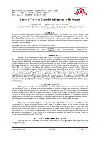
TEMPERATURE DISTRIBUTION OF THE OVEN
The cycle was programmed to maintain a temperature of 1050 0
C for 5 h allowing the materials to melt
and infiltrate the part. The oven then cools down to a temperature below 2000
C and the flow of nitrogen and
hydrogen is continued for maintaining a non-oxidative environment. The oven cycle for infiltration has been
given in fig. The materials were kept in contact with the porous green part to guarantee infiltration through
capillary action.
7. Effects Of Various Material …
www.theijes.com The IJES Page 16
Oven Temperature Distribution
HARDNESS TEST
BRINELL HARDNESS TESTING MACHINE
In Brinell hardness testing machine the load is applied by means of a single lever which is
hydraulically operated. The main lever can be raised or lowered by operating a lever. The oil necessary for the
hydraulic power is obtained from a pump driven by a fractional HP motor. An indicator in front shows the
positions of the loading lever and its movement, indicating the rate of applications of the load which can be
altered by adjusting a knob. A circular table mounted on a robust steel screw serves as a stage for the specimen
during the test. The table can be raised by rotating a handle wheel. The machine is supplied with two steel balls
5mm and 10mm in diameter. A star handle enables to bring the ball in contact with the surface of the specimen.
A steel ball of certain diameter is forced by a load into the specimen and the diameter if the indentation is
measured. Comparison of surface areas of indentation gives the measure of hardness.
Brinell hardness „HB‟ = load in kg / curved surface area of indentation in sq.mmQ
BIS SPECIFICATION FOR THE TEST
1. Thickness of the test specimen shall not be less than 8 times the depth of the indentation „h‟
Depth of indentation „h‟ = load in kg / (π × diameter × Brinell hardness)
2. The distance of the centre of indentation from the edge of test specimen shall be atleast 2 times the
diameter of the indentation in the case of steel (3 times the diameter of indentation in the case of light
metals like aluminium, magnesium and their alloys) and the distance between the centres of two
adjacent indentations shall be atleast 4 times the diameter of indentation in the case of steel (6 times the
diameter of indentation in the case of light metals and their alloys)
3. The applied load (kgs) shall be as follows
Material : load (kg)
Steel : 30D2
HB between 55 and 80 : 5D2
or 10D2
or 15D2
HB less than : 55
4. The test load shall be maintained for 10-15 seconds in the case of steel, 30±2 seconds in the case of
light metals and their alloys and 120±5 seconds in the case of magnesium and their alloys.
5. The Brinell Hardness number is calculated using the formula
Brinell hardness = 2P/ (πD (D-√ (D2
-d2
)
P = Load (in kg)
D = Diameter of Indenter (mm)
d = Diameter of Indentation (mm)
SURFACE ROUGHNESS TEST
A profilometer SURFCORDER SE1200, Kosaka Lab Ltd., was used to measure the surface roughness.
Average surface roughness values (Ra) were determined for each infiltrated components. Average surface
roughness values (Ra) in microns are measured. Measurement were made on infiltrated components of different
infiltrants like aluminium, bronze and magnalium and tabulated in table 6.1 One face of the components were
machined using surface grinder and the surface roughness values were noted and tabulated.
S.No Material
Diameter of the indenter
„D‟ (mm)
Load „P‟
(kg)
Diameter of indentation
„d‟(mm)
BHN
1 Brass 5 3000 4.81 74.95
2 Bell Metal 5 3000 4.75 76.65
3 Bronze 5 3000 4.71 85.2
8. Effects Of Various Material …
www.theijes.com The IJES Page 17
MEASURING CONDITION
Mode : ASME 95
Measuring values : Ra, Ry and Rz
Measuring speed : 0.5mm/s
Cut-off value : 0.8mm
Vertical magnification : auto
Return speed : 1.0mm/s
Cut- off value is the distance the stylus moves on surface. The maximum evaluation length for each cut- off
value is listed in table
Cut-off value (mm)
Maximum evaluation
length (mm)
0.08 0.72
0.25 2.25
0.80 7.20
2.5 22.50
Cut-off Value and Maximum Evaluation Length
REFERENCES
[1]. Sparrow, E. M., Baliga, B. R., Patankar, S.V., ”Forced Convection Heat Transfer from a Shrouded Fin Array with and without Tip
Clearance”, ASME J. Heat Transfer, Vol. 100, Nov. 1978, pp. 572-579.
[2]. Sparrow, E. M., Beckey, T. J., ”Pressure Drop Characteristics for a Shrouded Longitudinal-Fin Array with Tip Clearance”, ASME
J. Heat Transfer, Vol. 103, May 1981, pp. 393-395.
[3] F.P. Incropera, Convection heat transfer in electronic equipment cooling, J. Heat Transfer 110 (1988) 1097–1111.
[4] W. Nakayama, Thermal management of electronic equipment: a review of technology and research topics, Appl. Mech. Rev. 39
(12) (1986) 1847–1868.
[5] C.R. Biber, Pressure drop and heat transfer in an isothermal channel with impinging flow, IEEE Trans. Components Pack. Manuf.
Technol. A 20 (1997)458–462.
[6] Y. Kondo, M. Behnia, W. Nakayama, H. Matsushima, Optimization of finned heat sinks for impingement cooling of electronic
packages, J. Electronic Pack. (1998) 259–266.
[7] Z. Duan, Y.S. Muzychka, Experimental investigation of heat transfer in impingement air cooled plate fin heat sinks, J. Electronic
Pack. 128 (2006) 412–418.
[8] S. Sathe, K.M. Kelkar, K.C. Karki, C. Tai, C. Lamb, S.V. Patankar, Numerical prediction of flow and heat transfer in an
impingement heat sink, J. Electronic Pack. 119 (1997) 58–63.
[9] G. Ledezma, A.M. Morega, A. Bejan, Optimal spacing between pin fins with impinging flow, J. Heat Transfer 118 (1996) 570–577.
[10] Y. Kondo, H. Matsushima, T. Komatsu, Optimization of pin fin heat sinks for impingement cooling of electronic packages, J.
Electronic Pack. 122 (2000) 240–246.