
Recommended
More Related Content
What's hot
What's hot (20)
Similar to Mounting of bearing elements in concrete mixer design
Similar to Mounting of bearing elements in concrete mixer design (20)
Recently uploaded
Recently uploaded (20)
Mounting of bearing elements in concrete mixer design
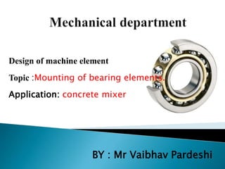
- 1. Design of machine element Topic :Mounting of bearing elements. Application: concrete mixer BY : Mr Vaibhav Pardeshi
- 2. Machine elements • Machine element is an individual component or a group of components of a machine which performs a perform a specific function. •Its function may be of holding the components together, to transmit power or to give supports. Depending upon these functions only, the machine elements are following types: 1. Machine elements used for holding the components. 2. Machine elements used for transmitting power. 3. Machine elements used for support of other components.
- 3. ELEMENTS OF CONCRETE MIXER 1. BEARINGS 2. WORM GEAR 3. DRUM 4. YOKE 5. SPROCKET 6. CHAIN DRIVE 7. MOTOR 8. ANNULAR GEAR 9. WHEEL CONTROL ASSEMBLY 10.FRAME 11.ANGLE PLATES
- 4. WORM GEAR
- 5. SPROCKET
- 6. Fr and Fa Shaft Diameter Application Find Co,C(Fa/VFr) and (Fa/Co),X and Y Select Ka and L10 Calculate Pe Required Dynamic Capacity Cr
- 7. DRUM
- 8. YOKE
- 9. BEARINGS
- 10. MOUNTING OF ELEMENTS •Shaft: A shaft is a rotating member, which is used to transmit power from one place to another place. in order to transmit power from one shaft to another the various members such as pulleys, gears etc are mounted on it. • Bearings: Bearings are used for carrying loads, while allowing relative motion with minimum friction. 1. Rolling contact bearings 2. Sliding contact bearings
- 11. ROLLING BEARING MOUNTING: The various bearing types and sizes require different mounting methods. As the hardened bearing rings are sensitive to blows, these must never be applied directly to the rings. On mounting of non-separable bearings , the mounting forces must always be applied to the ring which will have the tight fit and therefore is the first to be mounted. Forces applied to the ring with the loose fit would be transmitted by the rolling elements, thus damaging raceways and rolling elements. Mounting of separable bearings is easier, since the two rings can be mounted separately. In order to avoid score marks during assembly, slightly rotate the parts.
- 12. Method of bearing mounting 1. Both bearings are fixed. Left side bearing takes the thrust directed towards the left, while right side takes the thrust directed towards the right. 2. One bearing is fixed while the other is kept floating. In this type of mounting, the left side bearing takes thrust in both directions. 3. When two bearing are mounted on the shaft with their fronts facing each other. This is simpler and most widely used. 4. When two bearings are mounted on the shaft with their backs facing each other. This method is normally preferred when shaft is overhanging.
- 13. GEAR MOUNTING: A gear is a form of disc, or wheel, that has teeth around its periphery for the purpose of providing a positive drive by meshing the teeth with similar teeth on another gear or rack. Attachment with a fixing screw Assembly with a fixing screw is very simple. It just needs a threaded hole to be machined into the hub, and the machining of a flattened area on the shaft. The forces are concentrated on the edges of the cup headed screws . Attachment with a Key and Circlip Circlips, stop axial movement between two components. There are two types of circlips, one for shaft mounting and one for inside the bore.
- 14. .Attachment with a Cotter pin The cotter pin has the effect of immobilizing one component with respect to another, of assuring an accurate relative positioning of the two pieces, or of transmitting a movement. It can also play a safety role by shearing away in the event of a violent surcharge. Attachment with a Locking assy. By tightening the screws, the user deforms a conical ring, and causes a strong force between the shaft and bore. The liasion obtained is complete and rigid (i.e. backlash free) , and easily removed.
- 15. SELECTION OF BEARING FROM MANUFACTURERS CATALOG • INPUT BEARING 1 NO. = 6409 DAIMETER : 45 Co : 45500 N C1=72940.3 N • INPUT BEARING 2 NO. = 6309 DAIMETER : 45 Co : 30000 N C2=50391.8 N • INTERMIDIATE BEARING NO. = 6410 DAIMETER : 50 Co :52000 C1=86053.3 N • OUTPUT BEARING : 61807 DAIMETER : 35 Co : 3000 N C=3540.9 N
- 16. Introduction to Machine Design,V.B.Bhandari, Tata McGraw-Hill,2001