![Couplings do not normally allow disconnection of shafts during operation,
however there are torque limiting couplings which can slip or disconnect
when some torque limit is exceeded.
The primary purpose of couplings is to join two pieces of rotating
equipment while permitting some degree of misalignment or end
movement or both. By careful selection, installation and maintenance of
couplings, substantial savings can be made in reduced maintenance
costs and downtime.
In a more general context, a coupling can also be a mechanical device
that serves to connect the ends of adjacent parts or objects.[1]
Types of coupling:
1-Sleeve or muff coupling
It is the simplest type of rigid coupling, made of cast iron.
It consists of a hollow cylinder whose inner
diameter is the same as that of the shaft. It is fitted over the ends of
the two shafts by means of a gib
head key. The power is transmitted from one haft to the other shaft
by means of a key and a sleeve. It is, therefore, necessary that all
the elements must be strong enough to transmit the torque.](data:image/gif;base64,R0lGODlhAQABAIAAAAAAAP///yH5BAEAAAAALAAAAAABAAEAAAIBRAA7)
Recommended
More Related Content
What's hot
What's hot (19)
Similar to Coupling12
Similar to Coupling12 (20)
Recently uploaded
Recently uploaded (20)
Coupling12
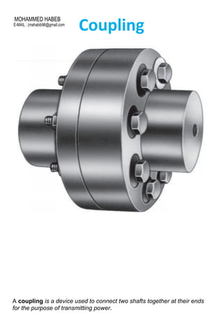
- 1. Coupling A coupling is a device used to connect two shafts together at their ends for the purpose of transmitting power. MOHAMMED HABEB E-MAIL : (mahabib96@gmail.com
- 2. Couplings do not normally allow disconnection of shafts during operation, however there are torque limiting couplings which can slip or disconnect when some torque limit is exceeded. The primary purpose of couplings is to join two pieces of rotating equipment while permitting some degree of misalignment or end movement or both. By careful selection, installation and maintenance of couplings, substantial savings can be made in reduced maintenance costs and downtime. In a more general context, a coupling can also be a mechanical device that serves to connect the ends of adjacent parts or objects.[1] Types of coupling: 1-Sleeve or muff coupling It is the simplest type of rigid coupling, made of cast iron. It consists of a hollow cylinder whose inner diameter is the same as that of the shaft. It is fitted over the ends of the two shafts by means of a gib head key. The power is transmitted from one haft to the other shaft by means of a key and a sleeve. It is, therefore, necessary that all the elements must be strong enough to transmit the torque.
- 3. 2- flange coupling: A flange coupling usually applies to a coupling having two separate cast iron flanges. Each flange is mounted on the shaft end and keyed to it. The faces are turned up at right angle to the axis of the shaft. One of the flange has a projected portion and the other flange has a corresponding recess.
- 4. There are three type of flange coupling: a-Unprotected type flange coupling b- protected type of flange coupling
- 5. c- Marine type flange coupling 3- Gear coupling Gear couplings transmit the highest amount of torque and the highest amount of torque in the smallest diameter of any flexible coupling. Each coupling consists of two hubs with crowned external gear teeth. The hubs mesh with two internally splined flanged sleeves that are bolted together. Gear couplings accommodate angular and axial misalignment by the rocking and sliding of the crowned gear teeth against the mating sleeve teeth. Parallel misalignment is accommodated by having two adjacent hub/sleeve flex points. Gear couplings require periodic lubrication depending on the application.
- 6. 4- flexible coupling a flexible coupling is used to join the abutting ends of shafts when they are not in exact alignment. In the case of a direct coupled drive from a prime mover to an electric generator, we should have four bearings at a comparatively close distance. In such a case and in many others, as in a direct electric drive from an electric motor to a machine tool, a flexible coupling is used so as to permit an axial misalignment of the shaft without undue absorption of the power which the shaft is transmitting. Following are the different types of flexible couplings a-Bushed pin flexible coupling In designing the bushed-pin flexible coupling, the proportions of the rigid type flange coupling are modified. The main modification is to reduce the bearing pressure on the rubber or leather bushes
- 7. 2- Oldham coupling It is used to join two shafts which have lateral mis-alignment. It consists of two flanges A and B 1with slots and a central floating part Ewith two tongues T 2and T 3-Universal (or Hooke’s) Coupling A universal or Hooke’s coupling is used to connect two shafts whose axes intersect at a small angle. The inclination of the two shafts may be constant, but in actual practice, it varies when the motion is transmitted from one shaft to another. The main application of the universal or Hooke’s coupling is found in the transmission from the gear box to the differential or back axle of the automobiles
- 8. Bearing A bearing is a machine element that constrains relative motion to only the desired motion, and reduces friction between moving parts. The design of the bearing may, for example, provide for free linear movement of the moving part or for free rotation around a fixed axis; or, it may prevent a motion by controlling the vectors of normal forces that bear on the moving parts. Most bearings facilitate the desired motion by minimizing friction. Bearings are classified broadly according to the type of operation, the motions allowed, or to the directions of the loads (forces) applied to the parts. Types of Rolling Contact Bearings:
- 9. 1- Ball bearings ball bearing is a type of rolling-element bearing that uses balls to maintain the separation between the bearing races. The purpose of a ball bearing is to reduce rotational friction and support radial and axial loads. It achieves this by using at least three races to contain the balls and transmit the loads through the balls. In most applications. 2- Roller bearing •Roller Bearings, in which cylinders are used instead of spheres, increasing the contact area so that it holds a greater radial load. Suitable for high radial loads and medium to high speeds 3-Thrust ball bearing The thrust ball bearings are used for carrying thrust loads exclusively and at speeds below 2000
- 10. r.p.m. At high speeds, centrifugal force causes the balls to be forced out of the races. Therefore, at high speeds, it is recommended that angular contact ball bearings should be used in place of thrust ball bearing. •4-Roller Thrust Bearings •which can support large thrust loads. Tapered Roller Bearings can support large radial and thrust loads.