1. Kopling
Dari Wikipedia bahasa Indonesia, ensiklopedia bebas
Belum Diperiksa
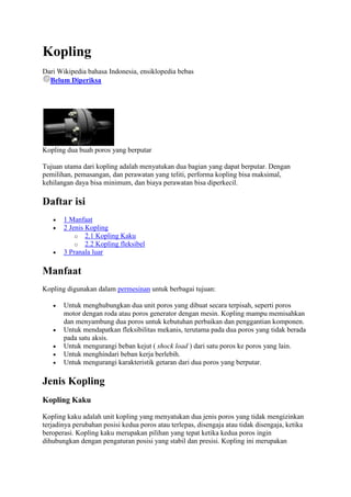
Kopling dua buah poros yang berputar
Tujuan utama dari kopling adalah menyatukan dua bagian yang dapat berputar. Dengan
pemilihan, pemasangan, dan perawatan yang teliti, performa kopling bisa maksimal,
kehilangan daya bisa minimum, dan biaya perawatan bisa diperkecil.
Daftar isi
1 Manfaat
2 Jenis Kopling
o 2.1 Kopling Kaku
o 2.2 Kopling fleksibel
3 Pranala luar
Manfaat
Kopling digunakan dalam permesinan untuk berbagai tujuan:
Untuk menghubungkan dua unit poros yang dibuat secara terpisah, seperti poros
motor dengan roda atau poros generator dengan mesin. Kopling mampu memisahkan
dan menyambung dua poros untuk kebutuhan perbaikan dan penggantian komponen.
Untuk mendapatkan fleksibilitas mekanis, terutama pada dua poros yang tidak berada
pada satu aksis.
Untuk mengurangi beban kejut ( shock load ) dari satu poros ke poros yang lain.
Untuk menghindari beban kerja berlebih.
Untuk mengurangi karakteristik getaran dari dua poros yang berputar.
Jenis Kopling
Kopling Kaku
Kopling kaku adalah unit kopling yang menyatukan dua jenis poros yang tidak mengizinkan
terjadinya perubahan posisi kedua poros atau terlepas, disengaja atau tidak disengaja, ketika
beroperasi. Kopling kaku merupakan pilihan yang tepat ketika kedua poros ingin
dihubungkan dengan pengaturan posisi yang stabil dan presisi. Kopling ini merupakan
2. kopling dengan usia pakai yang paling tinggi selama batasan torsi, RPM, dan beban dari
poros dan kopling tidak dilampaui.
Kopling fleksibel
Kopling beam dengan bagian ulir heliksnya
Rzeppa joint dan...
... Double Cardan Joint yang merupakan contoh dari kopling CV
Kopling roda gigi
3. Kopling Oldham
Universal joint
Kopling fleksibel digunakan ketika kedua poros ada sedikit perubahan posisi secara aksial,
radial, maupun angular ketika mesin beroperasi. Beberapa jenis kopling fleksibel yaitu:
Beam
Kopling CV (constant-velocity)
Diafragma
Disc coupling
Fluid coupling
Kopling roda gigi (gear coupling)
Hirth joint
Oldham
Rag joint
Universal joint
Kopling beam, atau bisa juga disebut dengan kopling heliks, adalah kopling yang
menghantarkan daya antara dua poros dengan memperbolehkan adanya perubahan posisi dari
poros secara angular, aksial, maupun paralel hingga batasan tertentu, ketika poros bekerja.
Desain dari kopling beam adalah sepotong kopling yang memiliki bagian yang kosong
sepanjang badan kopling berbentuk heliks atau spiral, sehingga menjadikannya fleksibel.
Kopling beam biasanya dibuat dari logam paduan aluminium, baja tahan karat, dan titanium.
Gear coupling adalah kopling yang mentransmisikan daya antara dua poros yang tidak berada
dalam satu garis. Kedua poros dihubungkan dengan poros ketiga di dalam kopling yang
disebut sebagai spindle.
Kopling CV adalah kopling yang memungkinkan untuk mentransmisikan daya pada sudut
yang bervariasi dan pada kecepatan putar yang konstan. Kopling jenis ini biasa digunakan
pada mobil front wheel drive dan all wheel drive.
Universal joint adalah jenis kopling dalam bentuk dua batangan kaku yang memungkinkan
terjadinya pembelokan arah transmisi daya dari sumber daya. Uniersal joint terdiri dari
sepasang hinge yang berdekatan dan dihubungkan dengan cross shaft. Universal joint, walau
dapat mentransmisikan daya yang tidak segaris, namun memiliki kekurangan, yaitu dapat
4. memberikan output RPM yang tidak konstan walau input RPM konstan. Hal itu bisa
menyebabkan getaran dan keausan pada komponen mesin.
Pranala luar
Wikimedia Commons memiliki kategori mengenai Kopling
Wikidata: Clutches
Shaft Coupling Glossary
List of coupling types
Flash Animation of Oldham coupler
Biography of Oldham at Cornell University
Animation Video of a shaft coupling
Yutaka Nishiyama, From Oldham's Coupling to Air Conditioners
A coupling is a device used to connect two shafts together at their ends for the purpose of
transmitting power. Couplings do not normally allow disconnection of shafts during
operation, however there are torque limiting couplings which can slip or disconnect when
some torque limit is exceeded.
The primary purpose of couplings is to join two pieces of rotating equipment while
permitting some degree of misalignment or end movement or both. By careful selection,
installation and maintenance of couplings, substantial savings can be made in reduced
maintenance costs and downtime.
Contents
1 Uses
2 Types
o 2.1 Rigid
2.1.1 Sleeve coupling
2.1.2 Flange coupling
2.1.3 Clamp or split-muff coupling
2.1.4 Tapered shaft lock
2.1.5 Hirth
o 2.2 Flexible
2.2.1 Bush pin Type flange coupling
2.2.2 Beam
2.2.3 Constant velocity
2.2.4 Diaphragm
2.2.5 Disc
2.2.6 Fluid
2.2.7 Gear
2.2.8 Oldham
5. 2.2.9 Rag joint
2.2.10 Universal joint
2.2.11 Others
3 Requirements of good shaft alignment / good coupling setup
4 Coupling maintenance and failure
5 Checking the coupling balance
6 See also
7 References
8 External links
Uses
Shaft couplings are used in machinery for several purposes. The most common of which are
the following.[1]
To provide for the connection of shafts of units that are manufactured separately such as a
motor and generator and to provide for disconnection for repairs or alterations.
To provide for misalignment of the shafts or to introduce mechanical flexibility.
To reduce the transmission of shock loads from one shaft to another.
To introduce protection against overloads.
To alter the vibration characteristics of rotating units.
To connect driving and the driven part
Types
Rigid
A rigid coupling is a unit of hardware used to join two shafts within a motor or mechanical
system. It may be used to connect two separate systems, such as a motor and a generator, or
to repair a connection within a single system. A rigid coupling may also be added between
shafts to reduce shock and wear at the point where the shafts meet.
When joining shafts within a machine, mechanics can choose between flexible and rigid
couplings. While flexible units offer some movement and give between the shafts, rigid
couplings are the most effective choice for precise alignment and secure hold. By precisely
aligning the two shafts and holding them firmly in place, rigid couplings help to maximize
performance and increase the expected life of the machine. These rigid couplings are
available in two basic designs to fit the needs of different applications. Sleeve-style couplings
are the most affordable and easiest to use. They consist of a single tube of material with an
inner diameter that's equal in size to the shafts. The sleeve slips over the shafts so they meet
in the middle of the coupling. A series of set screws can be tightened so they touch the top of
each shaft and hold them in place without passing all the way through the coupling.
Clamped or compression rigid couplings come in two parts and fit together around the shafts
to form a sleeve. They offer more flexibility than sleeved models, and can be used on shafts
that are fixed in place. They generally are large enough so that screws can pass all the way
through the coupling and into the second half to ensure a secure hold.Flanged rigid couplings
are designed for heavy loads or industrial equipment. They consist of short sleeves
surrounded by a perpendicular flange. One coupling is placed on each shaft so the two
6. flanges line up face to face. A series of screws or bolts can then be installed in the flanges to
hold them together. Because of their size and durability, flanged units can be used to bring
shafts into alignment before they are joined together. Rigid couplings are used when precise
shaft alignment is required; shaft misalignment will affect the coupling's performance as well
as its life. Examples:
Sleeve coupling
A sleeve coupling consists of a pipe whose bore is finished to the required tolerance based on
the shaft size. Based on the usage of the coupling a keyway is made in the bore in order to
transmit the torque by means of the key. Two threaded holes are provided in order to lock the
coupling in position.
Sleeve couplings are also known as Box Couplings. In this case shaft ends are coupled
together and abutted against each other which are enveloped by muff or sleeve. A gib head
sunk keys hold the two shafts and sleeve together. in other words, this is the simplest type of
the coupling. It is made from the cast iron and very simple to design and manufacture. It
consists of a hollow pipe whose inner diameter is same as diameter of the shafts. The hollow
pipe is fitted over a two or more ends of the shafts with the help of the taper sunk key.a key
and sleeve are useful to transmit power from one shaft to another shaft.
Flange coupling
This coupling has two separate cast iron flanges. Each flange is mounted on the shaft end and
keyed to it. The two flanges are coupled together with the help of bolts and nuts. The
projected portion of one of the flanges and corresponding recess on the other flange help to
bring the shaft into line and to maintain alignment. A flange which is provided with a shroud
which shelters the bolts heads and nuts is called protected type flange coupling.
Clamp or split-muff coupling
In this coupling, the muff or sleeve is made into two halves parts of the cast iron and they are
join together by means of mild steel studs or bolts. The advantages of this coupling is that
assembling or disassembling of the coupling is possible without change the position of the
shaft. This coupling is used for heavy power transmission at moderate speed.
Tapered shaft lock
A tapered lock is a form of keyless shaft locking device[2] that does not require any material
to be removed from the shaft. The basic idea is similar to a clamp coupling but the moment of
rotation is closer to the center of the shaft.[3] An alternative coupling device to the traditional
parallel key, the tapered lock removes the possibility of play due to worn keyways.[4][5][6] It is
more robust than using a key because maintenance only requires one tool and the self-centering
balanced rotation means it lasts longer than a keyed joint would, but the downside
is that it costs more.[citation needed]
Hirth
Main article: Hirth joint
7. Hirth joints use tapered teeth on two shaft ends meshed together to transmit torque.
Flexible
Flexible couplings are used to transmit torque from one shaft to another when the two shafts
are slightly misaligned. Flexible couplings can accommodate varying degrees of
misalignment up to 3° and some parallel misalignment. In addition, they can also be used for
vibration damping or noise reduction.This coupling is used to protect the driving and driven
shaft members against harmful effects produce due to misalignment of the shafts, sudden
shock loads, shaft expansion or vibrations etc.
Bush pin Type flange coupling
This is used for slightly imperfect alignment of the two shafts.
This is modified form of the protected type flange coupling. This type of coupling has pins
and it works with coupling bolts. The rubber or leather bushes are used over the pins. The
coupling has two halves dissimilar in construction. The pins are rigidly fastened by nuts to
one of the flange and kept loose on the other flange. This coupling is used to connect of
shafts which having a small parallel misalignment, angular misalignment or axial
misalignment. In this coupling the rubber bushing absorbs shocks and vibration during its
operations. This type of coupling is mostly used to couple electric motors and machines.
Beam
A beam coupling
A beam coupling, also known as helical coupling, is a flexible coupling for transmitting
torque between two shafts while allowing for angular misalignment, parallel offset and even
axial motion, of one shaft relative to the other. This design utilizes a single piece of material
and becomes flexible by removal of material along a spiral path resulting in a curved flexible
beam of helical shape. Since it is made from a single piece of material, the Beam Style
coupling does not exhibit the backlash found in some multi-piece couplings. Another
advantage of being an all machined coupling is the possibility to incorporate features into the
final product while still keep the single piece integrity.
Changes to the lead of the helical beam provide changes to misalignment capabilities as well
as other performance characteristics such as torque capacity and torsional stiffness. It is even
possible to have multiple starts within the same helix.
The material used to manufacture the beam coupling also affects its performance and
suitability for specific applications such as food, medical and aerospace. Materials are
typically aluminum alloy and stainless steel, but they can also be made in acetal, maraging
8. steel and titanium. The most common applications are attaching encoders to shafts and
motion control for robotics.
A beam coupling with optional features machined into it
Increasing number of coils allows for greater angular misalignment
Constant velocity
Main article: Constant-velocity joint
There are various types of constant-velocity (CV) couplings: Rzeppa joint, Double cardan
joint, and Thompson coupling.
Diaphragm
Diaphragm couplings transmit torque from the outside diameter of a flexible plate to the
inside diameter, across the spool or spacer piece, and then from inside to outside diameter.
The deforming of a plate or series of plates from I.D. to O.D accomplishes the misalignment.
Disc
Main article: Disc coupling
Disc couplings transmit torque from a driving to a driven bolt tangentially on a common bolt
circle. Torque is transmitted between the bolts through a series of thin, stainless steel discs
assembled in a pack. Misalignment is accomplished by deforming of the material between the
bolts.
Fluid
Main article: Fluid coupling
Gear
A gear coupling
9. A gear coupling is a mechanical device for transmitting torque between two shafts that are
not collinear. It consists of a flexible joint fixed to each shaft. The two joints are connected
by a third shaft, called the spindle.
Each joint consists of a 1:1 gear ratio internal/external gear pair. The tooth flanks and outer
diameter of the external gear are crowned to allow for angular displacement between the two
gears. Mechanically, the gears are equivalent to rotating splines with modified profiles. They
are called gears because of the relatively large size of the teeth.
Gear couplings and universal joints are used in similar applications. Gear couplings have
higher torque densities than universal joints designed to fit a given space while universal
joints induce lower vibrations. The limit on torque density in universal joints is due to the
limited cross sections of the cross and yoke. The gear teeth in a gear coupling have high
backlash to allow for angular misalignment. The excess backlash can contribute to vibration.
Gear couplings are generally limited to angular misalignments, i.e., the angle of the spindle
relative to the axes of the connected shafts, of 4-5°. Universal joints are capable of higher
misalignments.
Single joint gear couplings are also used to connected two nominally coaxial shafts. In this
application the device is called a gear-type flexible, or flexible coupling. The single joint
allows for minor misalignments such as installation errors and changes in shaft alignment due
to operating conditions. These types of gear couplings are generally limited to angular
misalignments of 1/4-1/2°.
Oldham
Animated Oldham coupler
An Oldham coupling has three discs, one coupled to the input, one coupled to the output, and
a middle disc that is joined to the first two by tongue and groove. The tongue and groove on
one side is perpendicular to the tongue and groove on the other. The middle disc rotates
around its center at the same speed as the input and output shafts. Its center traces a circular
orbit, twice per rotation, around the midpoint between input and output shafts. Often springs
are used to reduce backlash of the mechanism. An advantage to this type of coupling, as
compared to two universal joints, is its compact size. The coupler is named for John Oldham
who invented it in Ireland, in 1821, to solve a paddle placement problem in a paddle steamer
design.
10.
Oldham coupler, assembled
Oldham coupler, disassembled
Rag joint
Main article: Rag joint
Rag joints are commonly used on automotive steering linkages and drive trains. When used
on a drive train they are sometimes known as giubos.
Universal joint
Main article: Universal joint
Others
Bellows coupling — low backlash
Elastomeric coupling
o Bushed pin coupling
o Donut coupling
o Spider or jaw coupling (or Lovejoy® coupling)
Geislinger coupling
Resilient coupling
Roller chain and sprocket coupling
Schmidt coupling
Requirements of good shaft alignment / good coupling
setup
Main article: Shaft alignment
It should be easy to connect or disconnect the coupling.
It does allow some misalignment between the two adjacent shaft rotation axes.
Its goal should be to minimise the remaining misalignment in running operation so as to
maximise power transmission and to maximise machine runtime (coupling, bearing and
sealing's lifetime).
It should have no projecting parts.
11. It is recommended to use manufacturer's alignment target values to set up the machine
train to a defined non-zero alignment, due to the fact that later, when the machine is at
operation temperature, the alignment condition is perfect
Coupling maintenance and failure
Coupling maintenance is generally a simple matter, requiring a regularly scheduled
inspection of each coupling. It consists of:
Performing visual inspections, checking for signs of wear or fatigue, and cleaning couplings
regularly.
Checking and changing lubricant regularly if the coupling is lubricated. This maintenance is
required annually for most couplings and more frequently for couplings in adverse
environments or in demanding operating conditions.
Documenting the maintenance performed on each coupling, along with the date.[7]
Even with proper maintenance, however, couplings can fail. Underlying reasons for failure,
other than maintenance, include:
Improper installation
Poor coupling selection
Operation beyond design capabilities.[7]
The only way to improve coupling life is to understand what caused the failure and to correct
it prior to installing a new coupling. Some external signs that indicate potential coupling
failure include:
Abnormal noise, such as screeching, squealing or chattering
Excessive vibration or wobble
Failed seals indicated by lubricant leakage or contamination.[7]
Checking the coupling balance
Couplings are normally balanced at the factory prior to being shipped, but they occasionally
go out of balance in operation. Balancing can be difficult and expensive, and is normally
done only when operating tolerances are such that the effort and the expense are justified.
The amount of coupling unbalance that can be tolerated by any system is dictated by the
characteristics of the specific connected machines and can be determined by detailed analysis
or experience.[7]
See also
12. The clutch is a device used to connect two shafts at both ends for the
purpose of transmitting mechanical power . Clutch usually does not allow
the separation between the two shafts when operating , but currently there
is a clutch that has a limited torque so it can slip or disconnect when the
torque limit is skipped.
The main purpose of the clutch is to unite the two parts which can rotate .
With the selection , installation , and maintenance of a thorough , clutch
performance to the maximum , minimum power loss can , and maintenance costs
would be minimized .
Couplings used in machinery for a variety of purposes :
• To connect two shaft units are made separately , such as the motor shaft
to the wheel with the engine or generator shaft . Clutch is able to
separate and connect two shafts for the repair and replacement parts needs
.
• For mechanical flexibility , especially on the two shafts that are not
located on one axis .
• To reduce the shock loads ( shock load ) from one shaft to another shaft
.
• To avoid excessive workload .
• To reduce the vibration characteristics of two rotating shafts .
Rigid couplings
Rigid coupling is the coupling unit which brings together two types of
shaft which does not allow a change in the position of the shaft or
released , intentionally or unintentionally , when in operation. Rigid
coupling is the right choice when the shaft wants to be associated with a
stable position control and precision . This clutch is a clutch with the
highest service life limits for torque, RPM , and the weight of the shaft
and the clutch is not exceeded.
Coupling beam , or it could be called a helix clutch , is a clutch that
delivers power between two shafts to allow for the change in angular
position of the shaft , axial , and parallel to a limited extent , when the
shaft work . The design of the coupling beam is a clutch that has the
blanks along the body of a helical or spiral -shaped clutch , making it
flexible . Coupling beam is usually made of aluminum alloy , stainless
steel , and titanium .
Gear coupling is a coupling that transmits power between two shafts that
are not in one line . The two shafts are connected by a third shaft inside
the clutch are referred to as the spindle .
CV clutch is a clutch that allows it to transmit power at varying angles
and at a constant rotational speed . This type of coupling used on front
wheel drive cars and all-wheel drive .
Universal joint coupling is in the form of two types of rigid rod that
allows the deflection direction of transmitting power from the power source
. Uniersal hinge joint consisting of a pair of adjacent and connected by a
cross shaft . Universal joint , though not transmit power line , but has a
drawback, which can provide an output RPM is not constant even though the
input constant RPM . It can cause vibration and wear on engine components .