SlideShare a Scribd company logo
1 of 50
Download to read offline
CERBERUS: Autonomous Legged and Aerial Robotic
Exploration in the Tunnel and Urban Circuits of the
DARPA Subterranean Challenge
Marco Tranzatto1 ∗
Frank Mascarich2
Lukas Bernreiter3
Carolina Godinho4
Marco Camurri5
Shehryar Khattak1
Tung Dang2
Victor Reijgwart3
Johannes Löje4
David Wisth5
Samuel Zimmermann1
Huan Nguyen2
Marius Fehr3
Lukas Solanka4
Russell Buchanan5
Marko Bjelonic1
Nikhil Khedekar2
Mathieu Valceschini4
Fabian Jenelten1
Mihir Dharmadhikari2
Timon Homberger1
Paolo De Petris2
Lorenz Wellhausen1
Mihir Kulkarni2
Takahiro Miki1
Satchel Hirsch2
Markus Montenegro1
Christos Papachristos2
Fabian Tresoldi1
Jan Carius1
Giorgio Valsecchi1
Joonho Lee1
Konrad Meyer1
Xiangyu Wu6
Juan Nieto3
Andy Smith7
Marco Hutter1
Roland Siegwart3
Mark Mueller6
Maurice Fallon5
Kostas Alexis2
Abstract
Autonomous exploration of subterranean environments constitutes a major frontier for
robotic systems as underground settings present key challenges that can render robot auton-
omy hard to achieve. This has motivated the DARPA Subterranean Challenge, where teams
of robots search for objects of interest in various underground environments. In response,
the CERBERUS system-of-systems is presented as a unified strategy towards subterranean
exploration using legged and flying robots. As primary robots, ANYmal quadruped systems
are deployed considering their endurance and potential to traverse challenging terrain. For
aerial robots, both conventional and collision-tolerant multirotors are utilized to explore
spaces too narrow or otherwise unreachable by ground systems. Anticipating degraded
sensing conditions, a complementary multi-modal sensor fusion approach utilizing camera,
LiDAR, and inertial data for resilient robot pose estimation is proposed. Individual robot
pose estimates are refined by a centralized multi-robot map optimization approach to im-
prove the reported location accuracy of detected objects of interest in the DARPA-defined
∗1 Robotic Systems Lab, ETH Zurich, 2 Autonomous Robots Lab, University of Nevada, Reno — Norwegian University of
Science and Technology, 3 Autonomous Systems Lab, ETH Zurich, 4 Flyability, 5 Oxford Robotics Institute, University of Oxford
6 University of California, Berkeley, 7 Sierra Nevada Corporation, Direct correspondence to Marco Tranzatto marcot@ethz.ch
coordinate frame. Furthermore, a unified exploration path planning policy is presented to
facilitate the autonomous operation of both legged and aerial robots in complex underground
networks. Finally, to enable communication between the robots and the base station, CER-
BERUS utilizes a ground rover with a high-gain antenna and an optical fiber connection to
the base station, alongside breadcrumbing of wireless nodes by our legged robots. We report
results from the CERBERUS system-of-systems deployment at the DARPA Subterranean
Challenge Tunnel and Urban Circuits, along with the current limitations and the lessons
learned for the benefit of the community.
1 Introduction
This paper reports the technological progress made by team “CERBERUS” participating in the DARPA
Subterranean Challenge (SubT Challenge). The SubT Challenge is an international robotics competition
organized and coordinated by the Defense Advanced Research Projects Agency (DARPA) and calls on teams
to compete with respect to exploring, mapping and searching large-scale underground environments such
as tunnels or mines, urban subterranean infrastructure and cave networks. Responding to the requirements
of this challenge, this paper outlines the vision and technological developments of team CERBERUS, short
for “CollaborativE walking & flying RoBots for autonomous ExploRation in Underground Settings”. Team
CERBERUS corresponds to a combined system of legged and aerial robots equipped with multi-modal per-
ception capabilities, localization and mapping autonomy, as well as robot-deployable communications that
enables resilient navigation, exploration, mapping and object search inside complex, large-scale, sensor-
degraded and communications-denied subterranean environments. CERBERUS is developed based on an
international partnership, which up to the time of writing involves the Autonomous Robots Lab (University
of Nevada, Reno), Robotic Systems Lab (ETH Zurich), Autonomous Systems Lab (ETH Zurich), HiPeR
Lab (University of California, Berkeley), the Dynamic Robot Systems Group (University of Oxford), Flya-
bility and Sierra Nevada Corporation. This paper presents both the technological elements of CERBERUS
and detailed results of our team’s performance in the Tunnel and Urban Circuits, which were held in an
underground mine and a never-commissioned nuclear facility, respectively.
During the Tunnel and Urban Circuits, CERBERUS’ core robots were the “ANYbotics ANYmal B”
quadruped, and two classes of “Aerial Scouts”, namely multirotors with conventional airframes, as well
as the “Gagarin” class of collision-tolerant aerial robots. We have further added a roving robot called
“Armadillo”. ANYmal has the most extended endurance compared to all our robots and integrates our
multi-modal perception and autonomy solutions. At the same time, ANYmal can also deploy wireless com-
munication nodes. The Aerial Scout, with conventional airframe, is a traditional quadrotor design and acts
as a rapid explorer. The Gagarin collision-tolerant Aerial Scout is of smaller size and its mechanical structure
enables it to survive contact with surfaces and to make its way through challenging, narrow, multi-branched,
and possibly multi-level underground environments. Both aerial platforms integrate the CERBERUS multi-
modal perception and autonomy pipelines and operate without any human supervision after take-off. Lastly,
the Armadillo roving platform primarily deploys a high-gain wireless communications antenna deeper in the
underground environment, while maintaining an optical fiber connection to the Base Station. As a fall-
back role, this roving robot also integrates multi-modal perception capabilities to allow it to detect artifacts.
Figure 1 presents the CERBERUS robots deployed at the Tunnel and Urban Circuits of the SubT Challenge.
To enable autonomous exploration of subterranean environments, team CERBERUS focuses on multi-modal
and multi-robot perception, as well as path planning for exploration and area search. A unified complemen-
tary onboard perception solution is developed that fuses LiDAR, cameras, and inertial sensor cues. This
enables resilient localization and situational awareness even in conditions of perceptual degradation such as
geometric self-similarity, darkness and the presence of obscurants. The individual multi-modal perception
capabilities are further exploited at the level of multi-robot collaboration with map sharing and alignment
across the robotic systems of CERBERUS using centralized map optimization at the Base Station. In brief,
each robot can detect objects of interest in the field, and with map optimization, refine their position esti-
Figure 1: Instances of deployments of the CERBERUS robotic system-of-systems in the DARPA Subter-
ranean Challenge Tunnel and Urban Circuits. Upper row: ANYmal B on wheels and two standard ANYmal
B robots exploring sections of the Tunnel Circuit’s “Experimental” Course and Urban Circuit’s “Alpha” and
“Beta” Courses. Lower row: the Alpha and Gagarin Aerial Scouts in the Tunnel Circuit’s “Safety Research”
Course and the Urban Circuit’s “Alpha” Course respectively, alongside the Armadillo rover in the Urban
Circuit’s “Beta” Course. Relevant video results are available at http://bit.ly/cerberus2020
mates back at the Base Station. Building on top of this core capacity, CERBERUS uses a unified exploration
path planning solution on both legged and aerial robotic systems. The method relies on a graph-based search
and an information gain formulation related to volumetric exploration, avoids collisions, and accounts for
traversability limitations. While it enables efficient local search for optimized paths, it also enables the abil-
ity for automated homing and to travel to frontiers of the exploration space detected at earlier steps of the
robot’s mission. It is thus tailored to the large-scale, multi-level, and often narrow character of underground
environments.
As CERBERUS develops autonomous exploration and situational awareness through a team of robotic sys-
tems overseen by a Human Supervisor located outside of the underground environment, the final major
development priority relates to a robot-deployable communications solution. Maintaining a connection with
sufficient bandwidth as the robots proceed deeper into the subterranean environment is challenging due
to the size of the environments, along with their geometric and material properties. In response to this
challenge, CERBERUS utilizes customized 5.8GHz WiFi modules with each robot integrating its own anten-
nas, the ANYmal robots ferrying and being able to deploy communication breadcrumbs, and the Armadillo
rover integrating a high-gain antenna connected to the Base Station. This network allows for bidirectional
communication between the robots and to the Base Station, enabling both high-level control of the robot
behavior by the supervisor, as well as the reporting of detected objects of interest.
Alongside detailing the technological elements, we present how the robots operated in the underground mine
environments of the Tunnel Circuit and the abandoned nuclear facility of the Urban Circuit and discuss
technological adjustments in our solution. We compare our mapping results with ground-truth provided by
DARPA, specifically present the results of both the onboard and the multi-robot SLAM solutions, detail
and discuss the performance of our autonomy pipeline and when the single-operator exerted control, and
finally report the detected and missed objects of interest. Finally, we present an assessment of our team
performance both at the system level and for each technological component and focus on the challenges
faced and the lessons learned with the hope of informing other researchers contributing to this exciting field.
As significant components of our research have been released as open-source contributions, a selected list of
relevant software packages is also provided.
The remainder of this paper is structured as follows: Section 2 presents related work, while a high-level
overview of the CERBERUS vision is outlined in Section 3. The details about the individual robotic systems
are presented in Section 4. The two autonomy-enabling functionalities for exploration (path planning and
multi-modal multi-robot perception) are presented in Sections 5 and 6 respectively, followed by our object
detection and reporting solution in Section 7. The robot-deployable communications solution is outlined in
Section 8, while the Human Supervisor interface is discussed in Section 9. Experimental results primarily
from the DARPA Subterranean Challenge field deployments are presented in Section 10, followed by lessons
learned in Section 11. Finally, we present our plans for future work in Section 12, followed by conclusions in
Section 13. An appendix is also provided containing links to selected open-source contributions of our team,
alongside links from deployment results at the Tunnel and Urban Circuit events.
2 Related Work
The domain of subterranean exploration has attracted the interest of a niche community. The works in (Sil-
ver et al., 2006; Baker et al., 2004) present methods for topological exploration of underground environments
based on edge exploration and the detection of intersections. This work has been evaluated using ground
platforms with the Groundhog system demonstrating pioneering levels of exploration capacity. The contri-
bution in (Rogers III et al., 2017) presents methods for underground exploration using a team of UAVs.
The works in (Mansouri et al., 2019a; Mansouri et al., 2019b) outline methods for underground robotic
exploration - using aerial robots - via contour and junction detection. Similarly, the work in (Kanellakis
et al., 2019) utilizes methods based on open space attraction. The paper in (Jacobson et al., 2020) focuses on
the localization challenges in subterranean settings. From a systems perspective, the set of works in (Mor-
ris et al., 2006; Novák et al., 2015; Maity et al., 2013) overview innovations in the domain of ground and
submersible subterranean robotics. An overview of the utilization of ground robotic systems in underground
environments is provided in (Tardioli et al., 2019). Furthermore, the methods in (Bakambu and Polotski,
2007; Lösch et al., 2018) outline navigation solutions for robotic rovers underground. It should be noted
that the research challenges faced in such robotic missions relate to a breadth of research in the domains of
perception, planning, control, communications and more. This is reflected in the relevance of the challenges
faced in other competitions, including - but not limited to - the earlier “Multi Autonomous Ground-robotic
International Challenge (MAGIC)” as reported in papers from several of the participating teams (Olson
et al., 2012; Lacaze et al., 2012; Boeing et al., 2012; Butzke et al., 2012).
Accelerated by the kick-off of the DARPA SubT Challenge in September 2018, the domain of underground
robotic autonomy is currently experiencing rapid growth. The works in (Palieri et al., 2020) and (Tabib and
Michael, 2019) present accurate multi-sensor techniques for subterranean localization and mapping, while the
work in (Bouman et al., 2020) presents progress in the ability of legged robots to search such environments
autonomously. At the same time, the contribution in (Miller et al., 2020) uses multiple legged systems, while
a relevant dataset of artifact classification is released by the same team (Shivakumar et al., 2020). The work
in (Steindl et al., 2020) focuses on a hexapod design that has benefits in negotiating the challenging terrain
often encountered in subterranean applications. The work in (Hines et al., 2021) takes a different approach
using virtual surfaces to propose a cohesive mapping and planning solution for ground robots. Aiming to
explore scenes of interest better, the contribution in (Wang et al., 2020) helps in identifying areas of visual
interest through online learning, while the work in (Carlbaum et al., 2020) proposes a deep Convolutional
Neural Network (CNN) architecture to establish a novel feature tracking scheme for robust localization.
Focusing on the multi-robot operations aspect of underground autonomy, the authors in (Rouček et al., 2019;
Zoula et al., 2021; Goel et al., 2021; Corah et al., 2019) present methods for multi-robot exploration, map
sharing and communications. Contributing a largely different idea, the work in (Huang et al., 2019) proposes
the use of blimp system for long-endurance in underground exploration missions. Our team contributions are
aligned with these community efforts and aim to support the development of subterranean robotic autonomy.
3 CERBERUS System-of-Systems
The Defense Advanced Research Projects Agency (DARPA) created the DARPA Subterranean Challenge
(SubT Challenge) to incentivize research on novel approaches to explore, navigate, map, and search under-
ground environments with teams of robots. The underground domain features key challenges for mobile
autonomous systems including dynamic and rough terrain, limited visibility, poor communication, and hard
access. Extensive research in the fields of autonomy, perception, network, and mobility is therefore needed
to allow robots to explore these settings autonomously.
The SubT Challenge is structured in two parallel tracks, namely the “Systems” and the “Virtual” track.
In the former, teams choose to develop their own hardware and software to compete in a physical course.
In contrast, in the latter, teams choose to develop software-only solutions that are evaluated in simulation.
The proposed underground scenarios for the Systems track include man-made tunnel networks extending
for several kilometers and presenting vertical openings (“Tunnel Circuit” - August 2019), multi-level urban
underground structures with complex layouts (“Urban Circuit” - February 2020), and natural cave environ-
ments with complex morphology and constrained passages (“Cave Circuit” - August 2020, cancelled event).
Finally, the challenges of the previous circuits are combined in a comprehensive benchmark mission (“Final
Event” - September 2021).
The primary goal is to provide rapid situational awareness to small teams preparing to enter unknown and
dynamic subterranean environments. Therefore the competing teams are requested to explore and map
unknown underground scenarios, with the additional requirement that only one team member, the Human
Supervisor, can manage and interact with the deployed systems. Teams are scored based on their ability
to localize some specified objects, called “artifacts”, that represent features or items of interest that could
be reasonably found in subterranean contexts. The classes of the artifacts are known prior to each Circuit:
Survivor, Cell Phone, and Backpacks are common objects for all the Events; Drill and Fire Extinguisher are
specific to the Tunnel Circuit whereas Gas and Vent can be found at the Urban Circuit. A total of 20 such
objects are distributed along the Competition Course. Their positions are initially unknown to the teams.
If an artifact is localized and its position is reported within 5 m of its surveyed position, the team scores one
point. The artifacts’ surveyed positions are expressed with respect to a DARPA-defined coordinate frame.
The Tunnel and the Urban Circuit - which relate to the focus of this paper - each featured two different mission
courses in their respective environments. All teams were given two “scored runs” per course, scheduled on
different days. The total final score for each Circuit was computed as the sum of a team’s best run on each
course. Before the beginning of each run, the team’s Pit Crew (composed of up to nine people) had 30
minutes to complete the necessary setup of their Base Station and of the robotic systems before the actual
mission would start. The Base Station is a collection of one or more PCs used by the Human Supervisor
to interact with the deployed robotics agents. Moreover, it serves as an interface for forwarding artifact
reports and map updates to the DARPA Command Post, which evaluates the validity of the reports and
provides score updates. Each scored run lasted for 60 minutes and was the only time available for the teams
to explore and report the artifacts’ positions.
Motivated by and responding to these challenges, the CERBERUS collaborative walking and flying robotic
system-of-systems envisions the autonomous exploration of subterranean environments through the synergis-
tic operation of diverse systems with unique navigation capabilities. The principal idea behind CERBERUS’
vision is that the combination of legged and aerial systems offers unique advantages tailored to the needs of
complex underground settings. Walking robots present potential benefits for overcoming complex terrain,
both in terms of the size of obstacles that can be negotiated for a certain overall robot size, and robust
traversal of dynamic terrain. Aerial robots, especially when equipped with collision-tolerance capabilities,
offer the advantage of seamless navigation that is not bound to the extreme terrain challenges often present in
environments such as caves. CERBERUS focuses on the co-deployment of such legged and aerial robots that
are further equipped with resilient multi-modal and multi-robot localization and mapping, artifact detection
and universal exploration path planning capabilities. A robot-deployable communications network solution
is being realized which allows the CERBERUS system-of-systems to set up its own communications network
underground. Figure 2 depicts an illustration of a CERBERUS deployment. At the time of writing, a subset
of the technological components, methods and solutions have been developed and deployed incrementally at
the Tunnel and Urban Circuit events of the competition. The highlights of these developments are presented
in the rest of the paper. An appendix is provided that lists the open-source repositories containing our
research to facilitate its reproducibility and verifiability, which in turn can help accelerate the developments
of the community as a whole.
Figure 2: Graphical overview of the CERBERUS system: A single Human Supervisor outside the facil-
ity orchestrates the deployment of a heterogeneous team of quadrupeds and aerial robots. Our ANYmal
quadrupeds can traverse mobility hazards, while flying systems and especially the collision-tolerant robots
can act as scouts or used to detect artifacts in chimneys and shafts. ANYmal deploys communication nodes
to extend communication into the tunnel. The robots collaborate to reconstruct a consistent map, while
artifacts detected are reported in a global frame defined by DARPA.
4 CERBERUS Robots
This section outlines the CERBERUS robots, their system design and specifics with respect to subterranean
exploration functionality.
4.1 Subterranean Walking Robots - ANYmal B SubT
Team CERBERUS developed and deployed a team of legged robots specialized to operate in underground en-
vironments. These robots are based on the ANYbotics ANYmal B300 (Hutter et al., 2016) series quadruped,
and feature several hardware and software modifications to create a specialized subterranean version: the
ANYmal B “SubT” platform.
The ANYbotics ANYmal B300 series quadrupedal robot is a robust and agile legged system that is tailored
for autonomous, long endurance tasks under challenging environments. Each leg has three compliant joints
with integrated electronics which provide torque controllability and resilience against impact. This series
of quadrupeds have been developed for over 10 years and have achieved significant robustness, dexterity
and mobility, while maintaining a small size and weight with an endurance of 1 to 2 hours. In contrast
to wheeled or tracked systems, legged robots have the potential to adapt to terrain challenges by stepping
over obstacles (Jenelten et al., 2020) or adjusting their posture to crawl under obstacles (Buchanan et al.,
(a) Tunnel Circuit (b) Urban Circuit
Figure 3: ANYmal B SubT robot with specialized hardware and computation payload for deployment in
underground settings.
2021). They also allow for omnidirectional locomotion, which is advantageous inside narrow environments.
Additionally, legged machines can be combined with wheels to achieve high speed and energy efficiency,
combining the best of both worlds (Bjelonic et al., 2020). For this reason, legged robots are increasingly
used in industrial inspection applications (Bellicoso et al., 2018) and in the underground domain (Kolvenbach
et al., 2020). Consequently, other DARPA Subterranean Challenge competitors also deployed quadrupedal
robots during the Tunnel and Urban Circuits. For example, team PLUTO deployed four Ghost Robotics
Vision 60 during the Tunnel Circuit (Miller et al., 2020), and team CoSTAR, which used wheeled systems
during the Tunnel Circuit, later deployed two Boston Dynamics Spot robots (Bouman et al., 2020).
Hardware Modifications
Sensors - For the Urban Circuit, the onboard sensors were placed in two main locations atop the robot. A
front facing aluminum case included an Intel RealSense T265 Camera, a FLIR Blackfly S color camera, an
IMU, a VersaVIS synchronization board (Tschopp et al., 2020), a Velodyne Puck VLP 16 LiDAR, and a
Robosense BPearl LiDAR. A rear 3D-printed housing enclosed a Sensirion SDC30 gas sensor and two FLIR
Blackfly S cameras. The location of each component on the robot can be seen in Figures 3 and Figure 4.
All components in the front aluminum case are protected by a sheet metal structure. In order to have a
minimally obstructed field of view, the metal around both LiDARs is parallel to the pulsed laser beams of
the respective LiDAR. This setup is an improved version of the one deployed for the Tunnel Circuit, where
an Intel RealSense D435 Camera was used instead of the Robosense BPearl LiDAR.
Terrain Mapping Sensors - It is essential to ensure accurate terrain perception for safe navigation and
locomotion during autonomous missions. Therefore terrain mapping sensors should be accurate and reliable
in challenging environmental features such as darkness or reflective surfaces. Three different sensors were
compared: the Intel RealSense D435, the Pico Monstar and the Robosense BPearl. The RealSense is an
active stereo sensor that uses stereo matching with two IR cameras and complements it with active depth
sensing based on the projection of an IR pattern. The Pico Monstar is a time-of-flight camera that is devised
for long ranges and a wide Field-Of-View (FOV). The Bpearl is a dome-LiDAR that measures the reflection
times of emitted laser pulses using a hemispherical scanning pattern. An overview of the comparison results
is given in Table 1. The Pico Monstar and the RealSense were found to be prone to reflections (showing
missing data on wet ground) and other conditions of the surrounding environments (puddles, absorbent
material). Therefore the Bpearl was chosen as the terrain mapping sensor unit for the Urban Circuit, given
its accuracy and robustness in various conditions and its large 90° FOV.
Parallel Computing - The terrain mapping algorithms can be efficiently parallelized using a graphics pro-
cessing unit (GPU), while visual object detection also benefits from running neural-networks on a GPU. A
Jetson AGX Xavier was installed as an Auxiliary Graphics Processing Unit (AGPU). The unit is enclosed in
a 3D-printed PA-6 housing for protection against dust and water. Figure 4 shows the content of the AGPU.
Figure 4: Auxiliary Graphics Processing Unit (AGPU) package enclosing a Jetson AGX Xavier, an Arduino
Nano microcontroller, a Sensirion SDC30 gas sensor and two FLIR Blackfly S cameras.
Foot variants - To augment terrain specific locomotion capabilities, the legged robots were equipped with
three different types of feet. The standard version of ANYmal comes with point feet which adapt to any
inclination angle but are prone to slip. The flat feet developed in (Valsecchi et al., 2020) have a larger
contact surface and therefore provide more robust traction. To clear a considerable distance in a short time,
ANYmal was also equipped with actuated wheels (Bjelonic et al., 2020).
Payload Release Mechanism - The original belly plate of the robot, which protects the main body from
impacts, was modified to carry and release specialized WiFi Breadcrumbs (described in Sec. 8.3), as depicted
in Figure 5. A Dynamixel servomotor drives a slide screw which converts the rotary motion into linear
movement of a pusher plate. The modules are pushed towards an opening in the belly plate where leaf
springs prevent accidental release.
Software Modifications
Locomotion - Two different locomotion controllers were deployed on the ANYmal robots. During the Tunnel
Circuit, a model-based perceptive controller was utilized (Jenelten et al., 2020). The footholds and base
motion are sequentially optimized using a simplified description of the robot dynamics and while accounting
for the local terrain properties in a batch search. Additionally, a slip reflex (Jenelten et al., 2019) stabilizes
the robot in case of major slip events. In the Urban Circuit, a neural-network controller was deployed. It
was trained in simulation using reinforcement learning (Lee et al., 2020). The controller relies solely on
proprioceptive sensor information and uses a history of joint and IMU measurements to implicitly infer in-
formation about the terrain and external disturbances without depending on the local terrain map. While
the model-based controller performs motion planning with anticipation of terrain changes, the reinforcement
learning-based controller has significantly increased locomotion robustness in various challenging environ-
ments. During the Tunnel Circuit, ANYmal experienced corrupted local terrain representations leading to
incorrect locomotion controller actions that prevented the robot from continuing the mission. Therefore at
Sensor Type Note Size (mm) Weight (g)
RealSense Active Stereo Less accurate but functional under sun-
light
90x25x25 72
Pico Monstar Time-of-
Flight
Accurate but weak to sunlight or ab-
sorbent material
66x62x29 142
BPearl LiDAR Accurate, robust against sunlight or ab-
sorbent material but sparse
100x111x100 920
Table 1: Comparison of sensors for terrain mapping.
(a) Release mechanism. (b) WiFi beacon deployment.
Figure 5: ANYmal’s payload release mechanism and one deployable module (a). ANYmal deploying a WiFi
beacon on the ground (b).
Figure 6: Elevation map built by ANYmal during the Urban Circuit. Black cells indicate non-traversable
regions as classified by the learning-based traversability estimation.
the Urban Circuit the learning-based locomotion controller was employed due to its robust performance, as
well as its characteristic ability to plan footholds without relying on an explicit representation of the local
terrain.
Terrain Perception - As legged robots are constrained to move on the ground plane, a terrain representation
in the form of a 2.5D elevation map is commonly used. It is built in a robot-centric fashion from depth
sensor readings and robot odometry (Fankhauser et al., 2014). The map has dimensions equal to 12x12 m,
with a resolution of 4 cm. These settings reflect the sensor limitations and represent a trade-off between
capturing the surface of the terrain accurately and keeping the computation cost to a reasonable level for
onboard processing. In addition to the height value, a traversability value is computed for each grid cell.
The onboard state machine uses this information to prevent the robot walking into “non-traversable” areas.
Traversability values are computed with a two-layer CNN where the first layer applies multiple learnable
traversability templates to the height map and the second layer computes a weighted sum of template
activations (Wellhausen and Hutter, 2021). Since this network has only 120 learnable parameters, it can be
trained using only a dozen hand-labeled elevation maps and allows for rapid inference as it operates directly
on the elevation maps in GPU memory. A visual representation of the elevation map with associated
traversability estimation is shown in Figure 6.
Path Tracking - The path tracking module accepts paths from the autonomy module that are created
either by the the high-level exploration planner or by the Human Supervisor. This module is organized in a
hierarchical manner: a path manager converts the received paths (defined in an inertial frame) into a drifting
frame in which the robot’s locomotion controller operates. Subsequently it triggers the path following module
which computes twist commands for the robot to follow the given path.
State Machine - The capabilities for coordinating different software modules to execute autonomous missions
are provided by a multi-faceted state machine, whose interaction with the other main modules is depicted in
Figure 7. Its primary purpose is to minimize Human Supervisor interactions by automatically coordinating
between a high-level exploration planner, providing way-points where the robot should go, and a path track-
ing controller that steers the agent to the desired location. The state machine features a safety layer that
monitors and responds to events such as non-traversable terrain, unexpected obstacles or loss of communi-
cation. This software module operates in two different modes depending on the operator’s requirements: (a)
supervised-autonomous and (b) fully-autonomous mode. The former case is used when the operator has a
data connection to the robot, can check the high-level exploration planner’s goals, and can decide to overrule
the given way-points. During this mode, if communication to the Base Station is unexpectedly lost, the
robot is commanded to trace back its path until a connection is re-established and subsequently wait for the
supervisor to make a decision. The latter mode is used to explore regions without WiFi coverage. In this
case, the state machine does not take any action in case communication to the Base Station is lost. This
mode can be activated by the operator, alongside setting a time limit for autonomous exploration. Once
this time has elapsed, a homing request to the high-level exploration planner is issued, which will compute
a trajectory back to the Base Station. It is critical to get the robot back into the region with WiFi coverage
because the generated map and the identified artifacts need to be streamed back to the operator in order to
score points.
Despite the current operating mode of the state machine, if obstacles are detected along the robot’s direction
of motion, a traversability safety module is triggered. This module ensures that the robot reverses a fixed
distance and informs the high-level exploration planner about the non-traversable area (called a “geofence
zone”). The exploration planner will then re-plan a new path that avoids the obstacle. The state machine
uses the current robot’s direction to check if the agent is moving towards a non-traversable area. The
direction of motion is identified by performing a look-ahead projection of the robot’s future poses (up to
30 cm ahead) using its estimated velocity. Non-traversable obstacles are identified with the help of the
traversability estimation layer of the elevation map. The estimated look-ahead poses are used to anticipate
obstacles and to stop the robot sufficiently early. The state machine checks for the current robot’s direction
of motion instead of the high-level exploration planner’s path for a set of reasons. Firstly, the robot can
react to previously undetected non-traversable regions. Secondly, the portion of the elevation map closer
to the agent has higher accuracy. Lastly, checking the traversability of a path of several meters in a high
resolution map is computationally expensive. Therefore, checking for a relatively short range in front of the
robot is preferred.
4.2 Subterranean Aerial Robots
The SubT Challenge provides several unique challenges to autonomous robotic operation. Mines, caves,
and tunnels frequently contain many challenging terrain features and multi-level settings. Terrain obstacles,
including stairs, shafts both vertical and horizontal, boulders, cliffs, and bodies of water all impose significant
hazards to ground robots. Simultaneously, the elevated perspective inherent to aerial platforms provides
additional capabilities to observe, localize, and report artifacts. Despite limited endurance, aerial platforms
can cover more area in less time in many environments. Furthermore, they may correspond to the only
option for certain subsets of subterranean settings. Therefore, CERBERUS developed and deployed a team
of “Aerial Scouts” to provide rapid exploration capabilities, especially in regions of the course which were
inaccessible by ground robots.
System Design: Three robots, named Alpha, Bravo, and Charlie, utilize the DJI Matrice 100 quadrotor
as their airframe. For high-level processing, including sensor data collection, localization, mapping, and
planning, an Intel NUC Core-i7 computer (NUC7i7BNH) is mounted on each robot, while an Intel Movidius
Neural Compute Stick is used for artifact detection. As shown in Table 2, all three robots fuse LiDAR, visual
Figure 7: Schematic system overview of the main software modules on ANYmal, specifically tailored for
underground exploration missions. The components in the blue shaded area are executed on the onboard
computer. The yellow rectangles are ANYmal specific modules, whereas red rectangles indicate software
modules used also by the other CERBERUS’ robots.
and inertial data, while Charlie further integrates thermal vision and thus provides unique localization
capabilities in visually-degraded environments, as well as thermal object detection (e.g., for the survivor
artifact class). To enable perception in low-light environments, all three M100 Aerial Scouts are equipped
with Cree LEDs, which are synchronized with their visible light camera’s shutter producing a power-efficient
flashing behavior.
Figure 8: The Charlie (left) and Gagarin (right) Aerial Scouts.
A second - and particularly important for our team - class of Aerial Scouts, named Gagarin, also provides a
number of unique capabilities. This robot is designed to traverse narrow and visually degraded environments.
Gagarin is a drone surrounded by a collision tolerant cage that allows it to sustain collisions with obstacles
Alpha / Bravo Charlie Gagarin
Platform DJI M100 DJI M100 Collision-tolerant platform 1-3
Camera FLIR Blackfly S FLIR Blackfly S Intel RealSense T265
Thermal N/A FLIR Tau2 N/A
LiDAR Velodyne Puck LITE Ouster OS1 Ouster OS0 / OS1
IMU VectorNav VN-100 VectorNav VN-100 Integrated in autopilot
Table 2: Sensor suites used in different Aerial Scouts.
at speeds exceeding 2m/s. In order to thrive in narrow spaces, this drone has a compact design with a tightly
integrated power-efficient NVIDIA TX2 board with 6 ARM CPU-cores and a 256-core NVIDIA Pascal GPU,
an Ouster OS0 or OS1 (depending on the version of the Gagarin robot) LiDAR having a wide vertical FOV,
an IMU and two fisheye cameras, rendering it suitable for going through staircases and vertical shafts.
Additionally, to traverse visually-degraded environments, Gagarin has a custom lighting system involving
LEDs at different angles designed to reduce the effect of dust on the image, increasing the visual range and
enhancing the environment texture.
All Aerial Scouts communicate with the Base Station using their onboard 5.8GHz WiFi radios to connect di-
rectly to the Base Station antenna or through the breadcrumbs deployed by our legged robots. Importantly,
as reliable high-bandwidth communication becomes increasingly infeasible in most underground environ-
ments, the Aerial Scouts are able to operate completely autonomously with little to no input from the
Human Supervisor, and return to their home position before their batteries become depleted. The M100
Aerial Scouts are capable of flight times of 8 to 10 minutes, while the Gagarin collision-tolerant aerial scouts
present an endurance of 5 to 6 minutes.
Software Architecture: The Aerial Scouts all share the same software architecture, whose basic function-
alities are illustrated in Figure 9. Similar to other robots in the CERBERUS team, the Aerial Scouts use a
high-level exploration path planner, described in Section 5, to plan feasible paths for the robots. The path
is then tracked by a linear model predictive controller as in (Kamel et al., 2017) and the low-level command
is executed by the onboard autopilot inside each robot. The odometry feedback of the robots and the map
of the environment are provided by the multi-modal perception module presented in Section 6.
Operator Communication
Module
WiFi
Communication High-Level
Exploration Planner
Operator
Requests Position Control
(MPC)
Multi-modal
Perception
Robot
Autopilot
Path
Low-Level
command
Robot’s state
Map
NUC i7 (Alpha/Bravo/Charlie) / TX2 (Gagarin)
Figure 9: Schematic system overview of the core functional modules of the aerial scouts. All the components
inside the blue shaded area are executed onboard the robot. Yellow color depicts robot-specific functionalities,
while red is used for software components that are unified across the CERBERUS robots.
4.3 Roving Robots
Alongside the legged and aerial platforms, team CERBERUS also brought a roving robot called Armadillo
into the field. This ground vehicle is complementary to the walking and flying systems presented above.
System Design: Armadillo is based on the Inspectorbots Super Mega Bot (SMB) robot platform and was
chosen to complement the performance of the core CERBERUS team, primarily as a means to deploy a
high-gain communications antenna and due to its capability to carry large payloads and sensors. A custom-
designed frame, made of lightweight aluminum extrusions, was used to house all the components on the
robot. This frame was fixed atop Armadillo’s chassis and an onboard computer, namely a Zotac VR GO
Backpack PC, was placed inside the protected cage-like structure. A sensor-head, attached at the highest
part of the frame, houses various sensors to provide an unobstructed view of the environment.
The sensor-head on the Armadillo consists of a two level design having mounting points for all the sensors of
the robot. A FLIR Boson LWIR Camera and a FLIR Blackfly Color camera are mounted in the front facing
configuration alongside a VectorNav VN-100 IMU. Two identical FLIR Blackfly S cameras are mounted on
the sides of the sensor looking at either side of the robot. Additional FLIR Boson and Blackfly cameras are
mounted in a top-facing configuration for detecting artifacts on the ceiling.
A frame extension on the right side of the robot is made to mount a Robosense BPearl LiDAR Sensor that
Figure 10: The Armadillo roving robot - a modified Inspectorbots Super Mega Bot.
provides a dome-like view of the environment. At the back of the robot, a 300m-long optical fiber reel is
mounted with the capability of automatic unrolling while moving. This allows wired connectivity from the
Base Station to the robot. An additional 5.8GHz directional antenna is mounted in the front of Armadillo,
which allows the robot to act as a network range extender, providing high-bandwidth connectivity to the
Base Station.
Software Architecture: The Armadillo shared the same perception architecture as the flying robots.
However one significant difference is that - given its constant connectivity with the base-station through the
optical fiber connection and design choices of our team - it was manually controlled by the Human Supervisor.
The front facing Blackfly camera, the IMU and the Velodyne LiDAR are used for the multimodal perception
as described in Section 6. The remaining sensors provide a live feed to the operator at the Base Station.
5 Exploration Autonomy
The CERBERUS system-of-systems performs autonomous exploration and search for artifacts in the sub-
terranean environment based on a Graph-based exploration path planner (GBPlanner) (Dang et al., 2020)
that is universally designed and deployed across both legged and aerial robots. The method exploits a volu-
metric representation of the incrementally updated and explored 3D occupancy map M reconstructed based
on measurements from a set of onboard depth sensors {S}, as well as robot poses derived from each robot
localization system {O}. In the Tunnel Circuit M was based on the work in (Hornung et al., 2013), while
in the Urban Circuit the method in (Oleynikova et al., 2017) was employed. In both cases, M is using a
fixed resolution, thus each voxel has an edge size rV (throughout this work this value was set to rV = 0.2m).
The map consists of voxels m of three categories, namely m ∈ Mfree, m ∈ Moccupied, or m ∈ Munknown rep-
resenting free, occupied, and unknown space respectively, while certain (generally disconnected) subsets of
the map may correspond to “no-go” zones MNG (hereafter referred to as “geofences”) representing possible
traversability constraints or other imposed limits. Let dmax be the effective range, and [FH, FV ] be the FOV
in horizontal and vertical directions of each of the depth sensors S. In addition, let the robot’s configuration
at time t be defined as the 3D position and heading ξt = [xt, yt, zt, ψt]. Notably, since for most range sensors
perception stops at surfaces, hollow spaces or narrow pockets cannot always be explored fully. This leads
to a residual map M∗,res ⊂ Munknown with volume V∗,res which is infeasible to explore given the robot’s
constraints. As a result, given a volume V∗, the potential volume to be explored is V∗,explored = V∗  V∗,res.
Given this representation, the planning problem is organized based on a local and a global planning bifur-
cation. The overall planner architecture can be seen in Figure 11. In the local exploration planning mode,
given the occupancy map M and a local subset of it ML centered around the current robot configuration
ξ0, the goal is to find an admissible path σL = {ξi} in order to guide the robot towards unmapped areas
and thus maximize an exploration gain ΓL
E(σi), σi ∈ ΣL(set of candidate paths), primarily relating to the
volume expected to be mapped if the robot traverses along σL with a sensor S. A path is admissible if it is
collision-free in the sense of not colliding with 3D obstacles in the map and not going through geofences.
Given the subspace ML the local planning problem may report that no admissible solution is interesting
for the robot (zero-gain or below a set threshold). When this event, called “local completion”, occurs, the
global planning mode uses the latest M representation and the current robot configuration ξ0 to identify a
collision-free path σG that leads the robot towards the frontiers of the unmapped areas. Feasible paths of this
global problem take into account the remaining endurance of the robot. When the environment is explored
completely (“global completion”) or the battery approaches its limits, the method identifies an admissible
path σH that returns the robot to its home position ξhome. The functional specifics of these two modes are
outlined below.
Local Planner Global Planner
Best Path Shortest Paths
Graph
Path to Frontier Homing Path Global Graph
Improved Path Best Path
Path Improvement
Frontiers
Local Planner
Global Planner
Robot Speci c
Software
Common
Local Sampling Region
1
1
F2
F1
Geofence
Trigger Local
Exploration
Horizontal Exploration
Graph
Vertical Exploration
Graph
Figure 11: Functional diagram of the key functionalities of GBPlanner. This method bifurcates around a
local and global planning mode with the first responsible for efficient exploration around the current robot
location and the second responsible for re-positioning to frontiers of the explored volume in distant areas
of the map, as well as auto-homing. Special functionality is provided for multi-level exploration, while the
admissible paths account for collisions with 3D obstacles as well as “no-go” zones (geofences) that mark the
non-traversable regions detected.
5.1 Multi-Level Local Exploration Path Planning
The local planning mode of GBPlanner first iteratively builds an undirected graph GL inside the local map
space ML around the current robot configuration ξ0, which will be used to derive candidate exploration
paths. In the implementation of the planner, up to the Urban Circuit, the local map subset ML had a fixed
cuboid size set at the beginning of the mission (details for each robot are provided in Section 10). The
graph GL is built in the following manner. Given the updated occupancy map M, a bounded “local” volume
VDL
with dimensions DL centered around ξ0 and the respective map subset ML are first derived. Then
considering a bounding box DR representing the robot’s physical size (alongside the respective map subset
MR(ξ∗) for a robot state ξ∗), the planner samples a set of random configurations ξrand inside VDL
and after
checking which local connections (within a defined radius δ) are collision-free and outside of the geofences,
builds the graph GL with its vertex and edge sets V, E respectively. Subsequently, using Dijkstra’s shortest
path algorithm (Dijkstra et al., 1959), it derives paths ΣL in the graph starting from the root vertex at ξ0 and
leading to all destination vertices. Given a path σi ∈ ΣL, i = 1...µ with a set of vertices νi
j ∈ σi, j = 1...mi
along the path (corresponding to a set of robot ξ configurations), an information gain, called VolumeGain,
relating to the new volume anticipated to be explored is computed for each vertex νi
j. To compute the
VolumeGain at a vertex we count the number of unknown voxels inside a model of the sensor frustum
(accounting for the sensor range and field-of-view) centered at the vertex. This is done by ray casting into
the map with rays starting at the vertex. A fixed resolution of ray casting is employed. The exploration
gain ΓL
E(σi) for the path σi is then calculated as follows:
ΓL
E(σi) = e−ζZ(σi,σe)
mi
X
j=1
VolumeGain(νi
j)e−δD(νi
1,νi
j )
(1)
where ζ, δ > 0 are tunable factors, D(νi
1, νi
j) is the cumulative Euclidean distance from vertex νi
j to the root
νi
1 along the path σi, and Z(σi, σe) is a similarity distance metric between the planned path as compared
to a pseudo straight path σe with the same length along the currently estimated exploration direction. The
heading of every planned vertex is generally aligned with the direction of the respective path segment. While
legged systems are allowed to turn in place to ensure that the desired heading is reached, the aerial robots
are subject to a maximum yaw rate constraint. Therefore, a reachable heading as close as possible to that
of the direction of the path segment is assigned given the length of the path segment, the fixed reference
velocity, and the yaw rate constraint. Importantly, this local planning stage methodology implements a
specialized sub-bifurcation in its architecture to handle the case of multi-level/multi-storey environments
as, for example, encountered in the SubT Challenge Urban Circuit. In this mode, the method biases its
sampling of the local graph GL in order to sample densely in the vertical direction. Considering that a
depth sensor unveiling relevant space is available, this offers an artificial reward of exploration gain when
the robot changes “level” and thus identifies connections from the current level to the next. This motivates
the robot to take a staircase or other vertical passageway connecting two storeys of the environment. In
the implementation of the method as deployed up to the Urban Circuit event, it is the responsibility of the
Human Supervisor to select the appropriate local exploration mode.
In the case of legged robots, the path should not only be obstacle-free but also traversable. To that end, an
elevation map (see Section 4.1) is utilized to check for traversability along the robot’s direction of motion,
while following the planned path. The density of the elevation map is a trade-off between capturing the sur-
face of the terrain accurately and keeping the computation cost to a reasonable level for onboard processing.
Hence, the elevation map is calculated in a significantly smaller area than the size of the local map subset ML
which is used for exploration planning. However, planning only within short distances can lead to inefficient
exploration behavior. Therefore, the exploration path is calculated based on the occupancy map (specifically
ML), assuming that the areas outside the elevation map are traversable, and the traversability check is done
during path execution. If an area where the robot is walking towards is found to be non-traversable, the
path execution is stopped, that area is marked with a geofence, and the local planner is re-triggered. This
process, however, can lead to sub-optimalities as it may cause the robot to stop and re-plan when an initially
unknown non-traversable region is detected which in turn can slow down the exploration. To better address
this problem, longer range elevation mapping would be essential which in turn poses a set of computational
and sensing challenges as discussed in Section 4.1.
5.2 Global Exploration Path Planning
The global planning mode enables two critical behaviors in the exploration mission. First, upon local
completion of unexplored areas, the global planning mode enables the re-positioning of the platform to
unexplored areas of the map. Second, it permits autonomous homing upon reaching a critical point in the
time budget of the robot. To execute these behaviors, the planner maintains a computationally lightweight
global graph GG that contains vertices which potentially lead to unexplored parts of the environment called
“frontier vertices”, or simply “frontiers”. A vertex is marked as a frontier if the VolumeGain of that vertex
is found to be larger than a set threshold. At each local planning step, the frontier vertices from the local
graph GL are extracted and the frontiers within a radius λ of any existing frontiers in the global graph are
removed. The paths from the remaining frontier vertices to the root vertex of GL are extracted, clustered
together according to the Dynamic Time Warping (DTW) similarity metric (Bachrach, 2013; Dang et al.,
2020) and the principal path corresponding to the longest path from each cluster is retained. Finally, all the
principal paths are added to the global graph, as well as admissible edges connecting them to nearby global
vertices. In order to maintain a reduced list of frontiers in GG, vertices which no longer offer high gain are
eliminated by periodically re-evaluating each frontier vertex. Additionally, at every local planning step, the
planner needs to ensure that the robot has enough endurance to execute the path and return to the home
location. Hence, utilizing Dijkstra’s algorithm on the global graph, the planner identifies a return-to-home
path at each local planner iteration, and commands the robot to follow this path upon reaching the time
budget. It is noted that the homing path queries are fast due to the sparse nature of the global graph.
Choosing the best frontier to visit upon local completion is a difficult problem due to the size of the map
over which the search is executed, the uncertain knowledge of these frontier vertices, as well as their true
potential for exploration. Given these challenges, the selection of the frontier to visit depends on a) the time
budget remaining upon reaching that frontier and b) the volumetric gain for that frontier given the time to
reach it. Formally, let νG,cur be a vertex in the global graph representing the current robot configuration
and F = {νF
G,i}, i = 1...m be the set of updated frontiers. A Global Exploration Gain ΓG
E(νF
G,i) is evaluated
for each frontier as follows:
ΓG
E(νF
G,i) = T (νG,cur, νF
G,i)VolumeGain(νF
G,i)e−DD(νG,cur,νF
G,i)
(2)
where T (νG,cur, νF
G,i) is the estimated exploration time remaining if the planner chooses to visit the frontier
νF
G,i. This term is used to favor frontiers which lead to higher exploration times once they are reached. It
is approximately calculated using the remaining exploration time Te(t) (based on the robot’s endurance or
user-imposed mission time limit) at current instance t and the estimated time required to travel from the
current vertex to that frontier, Υ(νG,cur, νF
G,i), and from there to the home location, Υ(νF
G,i, νG,home), as:
T (νG,cur, νF
G,i) = Te(t) − Υ(νG,cur, νF
G,i) − Υ(νF
G,i, νG,home) (3)
The term D(νG,cur, νF
G,i) is the shortest path length from the current vertex to the frontier, which along with
the tunable parameter D penalizes longer paths.
Finally, the exploration path, local or global, is further improved by modifying all vertices in the path to be
further away from obstacles generating a safer path σr. The planner paths are provided to the robot-specific
local planners and controllers which are responsible for their execution.
6 Multi-Modal Perception for Multi-Robot Mapping
To enable robot autonomy in challenging subterranean environments, onboard perception plays a crucial
role in enabling reliable robot localization and navigation. Resilient robot perception, both in terms of
sensors and methods, is of particular importance for operation during the SubT Challenge as, in addition to
being GPS-denied, underground environments can impose various conditions of sensor degradation due to
their structural nature and operational conditions. Complete darkness, low-texture, geometric self-similarity,
thermal-flatness, and the presence of obscurants (smoke, fog, dust) are some of the challenging conditions
that can be encountered during the competition. Relying on any single sensing modality is unsuitable
for operation in such environments, and hence, the robots of team CERBERUS utilize multi-modal sensor
data from visual/thermal cameras, LiDARs, and IMUs in a complementary manner to provide reliability,
robustness, and redundancy for underground robot operations. This section details the processing of the
multi-modal sensor data to estimate the robot state and create a globally consistent multi-robot map.
First, sensor time-synchronization and calibration are discussed. Second, the utilized complementary multi-
modal fusion approach for onboard localization and mapping for individual robots is described. Finally,
the deployed global multi-robot mapping approach is detailed, along with the alignment of individual robot
frames B with the DARPA defined coordinate frame D, and transmission of maps to the Base Station.
Figure 12 depicts the used notation with coordinate frames and provides a general overview of the deployed
localization and mapping scheme. During the deployment, each robot builds and maintains an onboard
map of its traversed environment. These maps are periodically sent to the Base Station mapping server,
which combines individual robot maps and produces a globally optimized map. The self-contained onboard
localization and mapping approach enables the robots to explore autonomously, i.e., a connection to the Base
Station is optional. However, when connected, the global map allows, in particular, the Human Supervisor
to have a combined and optimized overview of the explored environment.
DARPA Gate
Base Station:
Global multi-robot mapping
(M3RM)
Mapping
Server
Artifact
Manager
Artifact
Artifact detections are expressed
relatively to the detecting robot
Maps with pointclouds
and DARPA Gate detection
Onboard:
Localization and mapping
(CompSLAM)
Global map with
associated artifact
locations
Figure 12: Illustration of the overall localization and mapping setup with coordinate frames for each robot
B1, B2 and B3. All robots align themselves with respect to a common DARPA-defined coordinate frame D
using fiducial markers on the starting DARPA gate. The mapping server on the Base Station receives maps
from the individual robots (blue) and combines them into a globally optimized map. Artifact detections,
such as a1, are recorded relative to the robot detecting them (B3) and are sent to the artifact manager (red)
for storing, additional inspection, and reporting them in coordinate frame D using the globally optimized
map to the DARPA Command Post for scoring.
6.1 Time Synchronization and Calibration
Precise time synchronization of the employed sensory systems is a crucial task for mapping and localization.
Although the robots only move at moderate velocities, the range at which they detect visual landmarks
and LiDAR points can be large. Given that small rotation changes can lead to large translations for points
that lie far away from the sensor frame’s origin, small timestamp inconsistencies between angular and linear
measurements can lead to significant systematic errors when distant points are observed.
The Armadillo robot (during the Tunnel Circuit) and the ANYmal robots (during the Urban Circuit)
employed a camera trigger board (Tschopp et al., 2020) capable of onboard synchronizing with a host
computer using time translation. An integrated Kalman Filter estimates the clock-skew and offset between all
sensors and the host computer. Additionally, since multi-camera systems inherently yield different exposure
times for each camera, the trigger board performs exposure compensation using the mid-exposure times.
Moreover, a tightly-coupled illumination board was used to trigger a set of LEDs according to the cameras’
exposure times for the flying robots and Armadillo. The LEDs are only turned on between the start of the
first camera and the end of the last camera’s exposure. This makes it possible to run the LEDs at a high
brightness while minimizing heat and energy consumption.
For the purposes of artifact localization and detection, as well as robot localization and mapping, a number
of calibrations are required. The color camera intrinsics and camera-to-IMU extrinsics were identified based
on (Furgale et al., 2013). The intrinsic calibration parameters of the thermal camera were calculated using our
custom designed thermal checkerboard pattern (Papachristos et al., 2018). The camera-to-LiDAR calibration
was derived based on an implementation of the work in (Zhou et al., 2018).
The Aerial Scouts operate with hardware-assisted software camera-to-IMU synchronization. While the cam-
era and the IMU are free-running, the internal functionalities of the VectorNav VN-100 IMU are used to
receive a synchronization pulse from the FLIR Blackfly S camera at the start of each exposure. Contained
within every IMU message is the time difference between the rising edge of the synchronization pulse and the
sample time of the current IMU message. IMU messages are assumed to be received in near real-time, and
therefore the image timestamps are corrected based on the time difference reported by the IMU subtracted
from the IMU message receive time.
6.2 Complementary Multi-Modal Localization and Mapping
To enable reliable and independent robot operation in challenging environments, the robots of team CER-
BERUS individually deploy an onboard complementary multi-modal localization and mapping (CompSLAM)
approach (Khattak et al., 2020). This approach fuses visual and thermal imagery, LiDAR depth data, and
inertial cues in a hierarchical manner and provides redundancy against cases of sensor data degradation.
A schematic overview of the proposed approach is shown in Figure 13. Camera images from both visual
and thermal cameras, as well as IMU measurements are fused using an Extended Kalman Filter (EKF)
estimator. The deployed EKF-estimator builds on top of the work presented in (Bloesch et al., 2017), due to
its low computational complexity, and extends it to concurrently operate on both visual and full-radiometric
thermal images, as described in (Khattak et al., 2019; Khattak et al., 2020).
To keep computational costs tractable while utilizing multi-spectral camera inputs, the Visual-Thermal-
Inertial Odometry (VTIO) estimator tracks a fixed number of features in its state by balancing the share
of tracked features from each image, subject to image quality using a spatial and temporal entropy eval-
uation (Khattak et al., 2019). The health of the odometry estimate is evaluated by measuring covariance
growth using the D-Optimality criterion (Carrillo et al., 2012). If the VTIO estimate is healthy, it is passed
to the Laser Odometry (LO) and Laser Mapping (LM) modules. The LO module first independently ensures
that the input estimate’s translational and rotation components are within robot motion bounds, set by the
controller, before utilizing it as a full or partial motion prior for the alignment of consecutive LiDAR scans.
Scan-to-scan alignment is performed by minimizing point-to-line and point-to-plane distances between ex-
tracted line and plane features, similar to the work of (Zhang and Singh, 2014). The quality of scan alignment
is checked by evaluating the minimum eigenvalues of the optimization Hessian matrix (Zhang et al., 2016),
and ill-conditioned dimensions are replaced with VTIO estimates before propagating the LO estimate and
providing it to the LM module, along with extracted scan features. The VTIO and LO modules provide
estimates at the update rates of images and point clouds, respectively; in contrast, the LM module operates
at half the LO module rate to remain computationally tractable. For this reason, the LM module also in-
dependently evaluates input motion estimates from both modules before using them to estimate the refined
robot pose in the local map using scan-to-submap alignment. Once a refined estimate is obtained, it is
checked using similar health metrics in the LO step, and the final estimate is utilized for the propagation of
the local robot map.
6.3 Global Multi-Robot Mapping
In addition to the onboard CompSLAM, robots with an established connection to the Base Station send maps
back to the mapping server, as well as artifact detections to the artifact manager. A centralized mapping
server allows the Human Supervisor to view and inspect artifact detections along with a combined multi-
robot representation of the environment. Generally, the global multi-modal, multi-robot mapping (M3RM)
approach is based on the existing framework Maplab (Schneider et al., 2018) and divided into two parts.
In the first part, each robot converts its raw sensor measurements into submaps that span consecutive time
intervals. Each submap consists of a factor graph, visual descriptors, and compressed LiDAR pointclouds.
LiDAR Mapping
LiDAR
Odometry
Visual-Thermal
Odometry
Input
Image
Evaluation
EKF
Odometry
Estimation
Health
Evaluation
LiDAR
IMU
Thermal
Camera
Visible
Camera
External Prior
Evaluation
Scan
Alignment
Optimization
Health
Evaluation
Odometry
Estimate
Propagation
Input
Odometry
Evaluation
Scan to
Submap
Alignment
Optimization
Health
Evaluation
Map
Propagation
(R,t)
Features
(R,t)
Figure 13: Overview of the deployed complementary multi-modal localization approach (CompSLAM). The
Visual-Thermal-Inertial Odometry module receives camera and IMU data and provides a motion prior to both
LiDAR Odometry and LiDAR Mapping modules to perform scan-to-scan and scan-to-submap alignments
respectively. Motion estimates between modules are only propagated if they pass individual health checks.
These submaps are then transferred to the mapping server. Building the submaps on the robots reduces
the required robot-to-mapping-server bandwidth, while only using a modest amount of computing power on
each robot. The second part takes place on the mapping server and consists of combining the individual
submaps into an optimized, globally consistent multi-robot map. The following subsections start by covering
the submap creation and transmission approach in more detail, followed by the submap merging and global
optimization strategy.
Submapping and Map Transmission over Network - Each robot builds an on-robot pose graph comprising
IMU, visual landmarks, and relative transformation constraints from the odometry. Furthermore, the on-
robot pose graphs are divided into chunks (i.e. submaps) and are periodically sent to the Base Station to build
a multi-robot map. The composed system is generally independent of each robot’s odometry estimation, i.e.,
the mapping system solely requires a consistent estimate of the robot’s state and the IMU biases. Specifically,
during the on-robot submap building, BRISK features are detected and tracked, and at submap completion,
triangulated to construct a local map using the odometry information. Consequently, this approach requires
motions within a submap such that uninitialized landmarks can be triangulated. In the case of motionless
submaps, which commonly occur at startup, a stationary edge connects the first and the last vertex in the
pose graph to avoid optimization issues.
In addition to visual landmarks, LiDAR scans are attached to the pose graph as resources using their
timestamp and extrinsic calibration. The attached LiDAR scans are associated with a specific location in
the pose graph and are not used for any additional computation on the robot itself but instead only on the
Base Station.
Submaps are created by splitting the local maps at a fixed time interval and are uniquely identified using
a hash of the timestamp and robot name. To ensure consistency in the submaps when combining them at
the Base Station, the first and last vertex of consecutive submaps overlap. The server additionally ensures
that the last and first vertex of consecutive submaps observe the same landmarks during the combination
and merges them accordingly. Before transmission, each submap is keyframed (Dymczyk et al., 2015) and
serialized to disk. A synchronization service then transfers the submaps to the Base Station in a granular
fashion (file-based), such that transfers can efficiently be resumed after sudden connection losses. Whenever
a submap transfer is completed, the synchronization service notifies the mapping server, which in turn
processes and merges the submap into the global map.
Globally Consistent Multi-Robot Mapping - The mapping server on the Base Station periodically checks for
completed submap transmissions and maintains a global map comprising all individual maps per robot.
During the optimization of the global map, the mapping server utilizes different types of constraints as
depicted in Figure 14. Maps from individual robots are connected by either merging visual landmarks (global
visual loop closure) or performing a dense alignment between spatially close poses. Moreover, each robot
Legend: Pose IMU Factors Visual Landmarks Odometry Factor Tag Alignment Dense Alignment
Robot 1
Robot 2
Robot 3
Figure 14: Illustration of three multi-modal pose graphs in the Base Station’s mapping server. The graphs
from individual robots are combined by co-observed landmarks or aligned pointclouds. Robot 1 and 3
detected the DARPA gate, whereas robot 2 was merged using shared landmarks.
performs an alignment to the DARPA frame D by detecting AprilTags on the Starting Gate with known 3D
coordinates. The camera position is found in DARPA frame coordinates by solving the perspective-n-point
problem of the 2D tag detections and its result is added to the pose graph as a prior factor. Incorporating
the DARPA frame alignment into the optimization has the advantage of including detection uncertainties,
being more robust against outliers, and being independent of the utilized sensor system. Additionally, this
facilitates the global map merging since the base frame of the robot’s map is already known.
Before merging a robot’s submap into the global map, each submap is processed by itself. The submap
processing performs a fixed number of operations, i.e., (i) a visual landmark quality check (ii) visual loop
closure (iii) LiDAR registrations, and (iv) optimization. Since the individual submap processing is indepen-
dent of other submaps, the mapping server processes up to four submaps concurrently. Furthermore, the
optimizations are limited to a maximum of two minutes to ensure fast iterations.
All new visual landmarks are first evaluated in terms of their distance, angle, and the number of observations.
Landmarks that do not fall within the thresholds for these criteria are marked as disabled during the
optimization. Next, visual-based loop closures (Lynen et al., 2015) are found using the tracked visual
BRISK features and an inverted multi-index. Loop closures are handled by merging the visual landmarks in
the pose graph, enabling the optimization to close loops solely using the reprojection error.
Furthermore, additional LiDAR constraints are extracted by registering consecutive scans within a submap
using Iterative Closest Point (ICP). The current states of the poses in the submap graph are used to
determine a transformation prior for the registration. Registration results that moderately contradict the
prior transformation are rejected as outliers to avoid constraints across floors or through walls. The remaining
registrations are added as relative 6DoF constraints between each scan’s closest pose in the submap where
the IMU is additionally utilized for interpolation between the timestamp of the scan and the pose. The
optimization assumes a fixed uncertainty for each registration constraint.
After the optimization, the submaps are merged into the current global multi-robot map. Similar to the
submap processing, the mapping server continuously performs a set of operations on the global map, i.e., (i)
global visual loop closure, (ii) global LiDAR registrations, and (iii) optimization. In contrast to the previous
submap processing, each operation utilizes all information from each robot’s currently explored areas. Hence,
the LiDAR constraints are found based on a proximity search within the global map. For each pointcloud
associated with the global pose graph, a radius search is performed to retrieve spatially close registration
candidates, including poses to other robots. Furthermore, all constraints resulting from LiDAR registrations
are implemented as switchable constraints (Sunderhauf and Protzel, 2012).
The global multi-robot map provides an overview of the explored areas to the Human Supervisor and allows
the operator to command robots to unexplored regions. Last but not least, artifact detections are utilized
together with the reconstructed map to query their location. When only the map onboard the robot is
available, the artifact locations are directly acquired, while when the M3RM-based map is also available,
then it yields optimized artifact locations.
7 Artifacts
In the SubT Challenge, teams are scored by reporting the class and location of a set of artifacts to the
DARPA Command Post. A fixed number of report attempts are given to each team for each Competition
Course. A point is earned for each report which correctly identifies the class of an artifact and its position
is within 5m of the object’s ground-truth location. Throughout both competition circuits, survivors, cell
phones, and backpacks were placed alongside drills and fire extinguishers in the Tunnel Circuit, followed
by CO2 (gas) sources and vents in the Urban Circuit. In this section, multi-modal artifact detection and
classification are described, including the initial detection onboard the robot, as well as how the detected
artifacts are attached to the global map presented in Section 6.3 such that their estimated positions can be
improved using the combined measurements of all robots.
7.1 Detection and Classification
Artifact detection and classification initially takes place onboard each robot. For the visible artifacts, sur-
vivors, cell phones, backpacks, drills, fire extinguishers, and vents, visual artifact detection using deep learn-
ing was employed. Specifically, we used YOLOv3 (Redmon and Farhadi, 2018) and its ROS porting (Bjelonic,
2018), trained on datasets featuring all DARPA-specified artifacts except CO2 gas. The training data con-
sists of images from both the aerial and ground platforms, in laboratory settings against backgrounds of
varying color, as well as in subterranean environments in varying lighting conditions. In addition, handheld
versions of robot sensor configurations along with the on-board lighting solutions were re-created to facilitate
rapid data collection and to improve viewpoint variation in the dataset. The number of images used to train
each class varies from a minimum of 1915 for the cell phone, to a maximum of 3519 for the fire extinguisher.
Table 3 details the number of training images used for each artifact class.
Artifact Survivor
Fire
Extinguisher
Cell
Phone
Drill Backpack Vent
No. Images 2660 3519 1915 3084 3388 2301
Table 3: Number of images used to train YOLOv3 for each class of visible artifact.
In addition to automatic detections, compressed image streams are sent back from the robots to the Base
Station, where the Human Supervisor is located. Using the Operator Interface described in Section 9, the
supervisor can pause and rewind these streams and manually select artifacts by clicking on the images. Given
the bounding box of an automatic detection or a click from the supervisor, the interface further allows to
manually add, translate, relabel and remove artifacts attached to the global map that can be reported to
the DARPA Command Post.
Due to the low precision-recall for visual cell phone detection, each robot could also detect the phone’s
Bluetooth signal, and report its presence to the Human Supervisor. In the Urban Circuit, all ground systems
additionally integrated a Sensirion SCD30 CO2 sensor to detect the gas artifact, reporting the position above
which the CO2 concentration had passed some threshold.
7.2 Map Attachment
The attachment of artifacts to the global map is performed in two steps. The first step takes place onboard
and consists of filtering the artifact detections to determine the artifact’s position in the robot’s local coor-
dinate frame. Referring to Figure 12, we denote the estimated position of the jth artifact in the body frame
of the robot which detected it with B
aj. In the second step, an artifact report is transferred to the mapping
server, where it is attached to the pose graph and its optimized position in the DARPA frame D
aj,opt can
be computed.
Due to the possibility of false positives and to prevent continuous artifact detections from saturating the
robot’s network connection to the Base Station, detections are first cast into the robot’s map, and then
filtered before being sent to the Base Station, providing the Human Supervisor with only high confidence
detections. Specifically, the bounding box containing the detected object in the image plane is divided into
a grid of pixels. These pixels are converted into rays using the camera model and the robot’s extrinsic
calibration parameters. Casting these rays into M results in a set of points that include points on the object,
as well as other surfaces contained within the bounding box. To approximate the object’s true position, the
median point is selected as the measured artifact position. To filter both multiple class detections and refine
the estimate of the artifact’s position aj, a sphere with radius Ra is drawn at the initial estimate of aj.
Additional detections whose projected positions lie within this sphere are considered to be detections of the
same object. For each sphere, separate binary Bayes filters for each artifact class are recursively updated
to estimate the probability that the sphere contains an object of a given class, and the sphere’s center aj is
further updated as the average position of all detections projected into the sphere. Once the probability of any
one class exceeds a predefined threshold, the artifact’s detection is considered “confirmed”. A summarized
detection report is sent to the Human Supervisor alongside a representative image of the artifact, and the
corresponding sphere is frozen to prevent any additional detections and subsequent duplicate reports. This
process is depicted in Figure 15.
Despite effort for automated localization of the cell phone’s position via a sequence of pose-annotated
Bluetooth-based detections and tracking of their RSSI values, it was determined that the most reliable
method would be to notify the Human Supervisor of the robot pose at which RSSI values of a cell phone
were detected. The supervisor could then improve the cell phone’s position by moving a marker on the
map or by drawing a bounding box around the cell phone in the camera images. In case the latter option
was used, the bounding box would be sent back to the robot, which would then convert it to a 3D artifact
position aj using the method described in the previous paragraph. In the Urban Circuit, this same approach
was used to determine the gas artifact positions.
Figure 15: Illustration of the process of casting automatic detections into the map. a) Shows the detection
of a backpack artifact with the image frame in blue, and the bounding box in green. b) The bounding box
is divided into a fixed grid. c) A ray from each grid cell is cast from the image plane until it intersects a
surface. d) The median ray, in red, is selected and a sphere of radius Ra, in orange, is placed in the map.
e) Subsequent rays from additional detections along the path shown in pink, which land within the sphere,
increase the confidence of the artifact category until reaching a threshold.
The artifact reports sent from the robot to the mapping server consist of the artifact’s type, the timestamp
ti at which it was “confirmed” and the artifact’s filtered position in the robot’s local frame Bti aj. The
annotated camera image in which the artifact was detected at time ti is also included to provide additional
context to the Human Supervisor. Once received by the mapping server, the artifact report is attached to the
pose graph node TDBti
that corresponds to the pose of the robot’s body in the DARPA frame D at timestamp
ti. The artifact’s most recent optimized position can then be computed as D
aj,opt = TDBti
,opt
Bti aj. When
desired, the artifact’s unoptimized position can also be recovered with D
aj,unopt = TDBti
,unopt
Bti aj.
8 Networking
During mission deployments, all robots communicate with the Base Station via an ad hoc wireless network
to share mapping data, artifact locations, and other information. This network operates in the 5.8GHz range
and is progressively built by the robots that can communicate with each other and extend the network by
dropping additional WiFi nodes. This section describes the hardware and software configuration that enables
remote networking of the agents in the underground. Figure 16 shows an overview of the communication
architecture used by team CERBERUS.
Figure 16: Block-diagram view of the networking infrastructure used during the Tunnel and Urban Circuits.
Roving and quadrupedal robots, as well as dropped communication nodes, create an ad hoc mesh network,
which establishes the backbone communication infrastructure. The roving robot was also equipped with a
fiber optical cable to maintain connection to the Base Station. Aerial scouts used a standard (802.11) WiFi
network, created either by a directional antenna at the Base Station or by a dropped breadcrumb.
8.1 Mobile Agent Nodes
Agents employ two different hardware methods. Ground robots are equipped with a commercial off-the-shelf
device (ACKSYS Communications  Systems - EmbedAir1000) that supports WiFi access point, client,
repeater, and MESH point modes. In mesh mode, these devices create a mesh network, that is a local
network topology in which the infrastructure nodes connect directly, dynamically and non-hierarchically to
as many other nodes as possible and cooperate with one another to efficiently route data from/to clients. In
this way, ground robots establish a backbone wireless network shared among the other agents.
Due to their limited payload capability and size constraints, the aerial robots did not carry mesh node-capable
devices and acted solely as clients. They connect to the closest existing wireless access point, broadcast either
by the Base Station or by nodes deployed by ground robots.
8.2 Base Station Network
In preparation for a wide variety of competition scenarios, the team prepared four solutions to provide
communications from the Base Station into the subterranean environment. First, the Base Station uses an
ACKSYS EmbedAir1000 WiFi radio and connects to the mesh network using a high gain, directional panel
antenna from L-Comm; supplying a high bandwidth connection both within the Staging Area as well as
deep into the competition area. Second, Armadillo was deployed with a 300m-long optical fiber cable, a
panel antenna, as well as a multi-modal perception system that further allowed it to be remotely controlled
by the Human Supervisor while extending the WiFi network around corners and down corridors with ease
in relative proximity to the Base Station. Third, a panel antenna was attached to a PVC pole and angled
to provide a network down a stairway very near the competition gate. The pole was manually extended
and oriented down the stairway by a team member. Finally, an EmbedAir1000 WiFi radio and its battery
were placed in a foam ball which was manually thrown by a team member down a stairway to provide a
network connection to the lower level of the circuit. The Gagarin Aerial Scout utilized both the ball and
pole antennas while exploring the staircase.
8.3 Deployable Mesh Nodes
ANYmal robots were able to carry additional WiFi nodes and deploy them on the ground to expand the reach
of the wireless mesh network incrementally. Each robot was able to store four modules inside its belly plate
and release them by lowering the torso height and activating the payload release mechanism described in
Section 4.1. Each node is a water and dustproof self contained unit, consisting of a battery pack (allowing
approximately two hours of operation), a battery management system, a magnetic switch (to switch the
module on after releasing it), an LED to aid the recovery of the module after the mission, two WiFi patch
antennas, and an EmbedAir1000 module (see Figure 5). In as ideal as possible underground conditions, such
as a straight tunnel, the modules can reliably communicate within a range of 100 m when dropped on the
ground. However, due to obstructed lines of sight from solid material (e.g., in a mine corner), multipath
and reflections in underground settings, performance may vary considerably. As evaluated via experimental
observations, close to the first communication module a maximum available bandwidth of approximately
200Mbps was observed. In team deployments, the legged robots and the droppable communication nodes
had both radios of the EmbedAir1000 module enabled to maximize the communication performance and
maintain as much of the initial bandwidth as possible across the deployed communication topology.
The Human Supervisor was left in charge of deciding the deployment location, as wireless signal propagation
is often unpredictable in subterranean scenarios. (Rizzo et al., 2013) show that a deviation in robot trajectory
of a few centimeters can cause a significant difference in terms of received power on its onboard mesh receiver.
In a more recent analysis, (Tardioli et al., 2019) show that due to destructive self-interference of signals
reflecting off tunnel walls, there is a highly varying fading effect which leads to Received Signal Strength
Indication (RSSI) having a variance of up to 30 − 40%. As a result, RSSI can be a misleading indicator
to check the quality of a wireless connection inside a tunnel. Moreover, this variance can result in a link
between two nearby mesh nodes reporting a worse signal strength than between nodes further apart. These
peculiar characteristics, therefore, make an automatic decision of where to deploy mesh nodes a non-trivial
problem. As a result, the deployment location was decided by the Human Supervisor. This decision was
based on information about signal quality (such as the output of ping utility) between the Base Station and
the agent, as well as considerations about the geometry of the environment surrounding the robot.
8.4 Nimbro - Multi-Master Network
The Robot Operating System (ROS) was used as middleware for message passing to enable communication
between processes running on each robot, as well as across robots on the same network. However, ROS
requires a rosmaster process which monitors all communication connections. There can only be one ros-
master on a given network and typically, this process is run onboard a robot’s computer in case there is
communication loss with the Base Station. This presents a challenge in scenarios with multiple robots, each
with their own rosmaster, communicating on the same network to the same Base Station.
The Nimbro Network1
software package allows the generic transport of ROS topics and services over unreli-
able network connections and has been deployed in several robotic challenges (Stückler et al., 2016; Schwarz
et al., 2017). Since it avoids any configuration/discovery handshake, it is suited for situations like the SubT
Challenge where wireless connections can drop and recover unexpectedly. Its primary purposes are to de-
couple multiple rosmasters and select which data are transmitted between agents and the Base Station. A
hardcoded list of data to be exchanged may be cumbersome to maintain and adapt, especially when tools
such as multimaster fkie (Tiderko et al., 2016) offer the possibility to automatically establish and manage
a multi-master network with little or no configuration. However, these automatic tools require extra cus-
tomization to be adapted to the SubT Challenge, as done by team CoSTAR (Queralta et al., 2020) and
may be error-prone, transmitting unnecessary data and using limited bandwidth. Therefore, given that an
ANYmal robot had more than 800 topics and 400 services in its ROS system, the alternative to clearly
identify which data streams should be transmitted and not rely on any automatic decision was preferred. A
key factor in a system with multiple rosmasters is time synchronization between the agents and the Base
Station. This was achieved through the usage of the software tool chrony2
. chrony is an implementation of
the Network Time Protocol (NTP) that can synchronize the system clock with a predefined server. In this
use case scenario, each robot acted as a client of the Base Station, which was the main NTP server.
9 Operator Interface
A crucial aspect of the SubT Challenge is the single Human Supervisor at the Base Station. This person is
the only individual allowed to coordinate, manage, and monitor the deployed systems. The single operator
requirement is intended to minimize the amount of human intervention for this type of autonomous mission
and forces the robots to have a high level of autonomy, while remotely mapping and/or navigating complex
environments.
During the Tunnel and Urban Circuits, the Human Supervisor used a custom and integrated solution for the
Base Station setup (see Figure 17). This solution was composed of a sturdy box (Peli Air Case - Pelican)
containing electronic components (WiFi router, auxiliary screen, etc.). It ensured fast deployment and
setup of the Base Station. The supervisor used two main software modules to interact with the deployed
robots: a Mission Control Interface (MCI), and an Artifacts Reporting Interface (ARI), exposed through a
Graphical User Interface (GUI) (see Figure 18). The MCI was used to (a) check the status of each agent,
(b) give high-level commands to override the current robot’s behavior and (c) request specific sensor data to
evaluate the current situation better. The ARI was used by the Human Supervisor to (a) have a top-down
view of the global map created during the mission, (b) visualize throttled and compressed image streams
from the agents, to manually report artifacts, and to (c) check, and approve or discard artifacts that were
automatically detected by the robots.
Team CERBERUS adapted its approach towards the single Human Supervisor requirement between the
Tunnel and Urban Circuits, improving the GUIs to control multiple agents, as well as the amount of ex-
changed data between robots and the Base Station. Major changes to the communication architecture were
introduced. These are highlighted in the following sections.
9.1 Robot Control
During the Tunnel Circuit, each robot received commands from the Human Supervisor via a dedicated
Operator’s PC (OPC). An OPC was specifically set up to interact with one or more robots. It used the
1https://github.com/AIS-Bonn/nimbro_network
2https://chrony.tuxfamily.org/
(a) Base Station. (b) Tunnel Circuit setup. (c) Urban Circuit setup.
Figure 17: Setup of the Base Station for the Human Supervisor. Operator’s box with external screen and
docking station (a). Setup for Tunnel Circuit: one PC for aerial robots, two PCs to control two ANYmal
robots, one PC for the Armadillo rover, and the main ARI running on the screen of another PC (b). Setup
for Urban Circuit: one PC for aerial robots, one PC to control all ground robots, and the main ARI running
on the screen of another PC (c).
rosmaster of the corresponding robot and was used to initialize the agent (launching procedure, detection of
the DARPA gate, etc.). Every ground robot operated in conjunction with its own OPC, and could stream
all requested topics to the supervisor. On the other hand, all the aerial scouts could be controlled - one
at a time - by another OPC. Each of these OPCs run its own instance of MCI, customized based on the
type of robot. Only Aerial Scouts took advantage of the multi-master architecture with the Nimbro Network
software package (described in Section 8.4), whereas ground robots used it only to report artifacts and map
updates. Once each robot was set up by the Pit Crew and ready to start the mission, its OPC was passed
to the Human Supervisor that could then use it to deploy the robot. The described setup resulted in an
extra burden for the single Human Supervisor who had to deal with multiple PCs to execute the mission.
For example, to control two ANYmals, one wheeled ground robot and aerial robots, the supervisor had to
deal with four different OPCs, plus the additional PC running ARI - see example setup in Figure 17b. This
approach was not sustainable, and therefore specific modifications were applied for the Urban Circuit.
A different setup of the Base Station and for controlling the robots was employed during the Urban Circuit.
Every robot leveraged the multi-master architecture with the Nimbro Network package and exported only a
subset of the ROS topics and services to its MCI. This prevented the wireless network from being cluttered
with data that was not strictly needed for the mission execution. Moreover, the concept of “on-demand”
topics was introduced: sensor data such as LiDAR scans and elevation maps require a considerable amount
of bandwidth to be streamed over WiFi, and are most of the time not necessary to be continuously sent to
the Human Supervisor. Therefore a single message of these data streams was sent only upon request of the
supervisor via the MCI. Each robot still had its dedicated OPC, but it was used solely for agent setup by
the Pit Crew prior to the deployment. The overall startup procedure included one PC to run the instances
of MCIs for all ground robots, and one other for the MCI for aerial robots. This meant that to control two
ANYmals, the Armadillo rover and the aerial scouts, the Human Supervisor had to deal with two computers,
located at the Base Station (see Figure 17c).
In both Circuits, the Human Supervisor was able to supervise the decisions taken by each agent and, if
required, decide to re-define the exploration bounding box in which each robot was allowed to explore. In
every assigned area as defined by the planner bounding box, each robot was exploring the unknown space
autonomously without relying on external information. If necessary, the Human Supervisor was able to
overrule the autonomous planner and provide way-points to any robot.
9.2 Artifact Reporting
The artifact reporting interface (see Figure 18c) is designed to reduce the strain on the Human Supervisor
while improving situational awareness and reducing the chance of reporting mistakes. It is composed of
panels showing video streams from the selected robots, a panel notifying the supervisor of all new automatic
(a) ANYmal MCI. (b) Aerial Scout MCI. (c) ARI
Figure 18: Mission Control Interfaces (MCI) for ANYmal (a) and aerial scouts (b). They have a similar layout
but feature some customization based on the specific type of robot. The minimal amount of data displayed
to the Human Supervisor reflects the need to reduce streamed data from each robot to the essential ones:
a frame representing the robot’s pose in the map, requested LiDAR scans and/or elevation map snapshot,
information about automatically detected artifacts and their location. The Artifact Reporting Interface
(ARI) combines video streams from all robots, a panel to accept and modify artifact detections, and an
overview of the reported global dense map overlaid with the state of all detected artifacts (c).
artifact detections, an RViz window showing all detected artifacts in the global dense map, and a text window
for important system errors. The video streams can be paused and rewound, allowing the supervisor to better
understand the areas explored by the robots. In case some artifacts were not detected automatically by the
robots, a bounding box can be drawn on the image to attach the artifact to the map as discussed in section
7.2. When the Human Supervisor is notified of a new automatic artifact detection, the associated camera
image, annotated with the artifact’s bounding box and class, is shown for context. Under normal operation,
the supervisor would accept the artifact, which would then be added to the multi-robot global map. As a
fallback, the supervisor is also able to bypass the automatic artifact type detection and mapping server and
file artifact reports directly to the DARPA Command Post.
Once an artifact has been added to the multi-robot global map, it appears in an RViz panel together with
the optimized global dense map. For additional context, the artifact’s original position, optimized position,
and the robot pose from which it was observed are shown. Interactive markers are used to allow the Human
Supervisor to report, modify, and delete artifacts through a right-click menu. Whenever an artifact is
selected, its associated annotated camera image is shown in a dock next to the map. This proved very
helpful for the supervisor to recall and distinguish artifacts. Once an artifact is reported, its color changes
from cyan (not yet reported) to green (valid) or red (invalid) depending on the response from the DARPA
Command Post. As the robots explore the environment further, the global map improves due to additional
measurements, including loop closures. When significant improvements occur, the Human Supervisor can
submit new reports for artifacts that were initially rejected.
9.3 Fallback Solutions
Given the centralized nature of the reporting architecture, special care is taken to minimize the damage to
the team’s competition score in case of system malfunctions on the Human Supervisor’s PC at the Base
Station. Starting at the hardware level, a custom-built server is used as the Operator PC. To provide
robustness to temporary power losses, it is powered through an Uninterruptible Power Supply. At the
software level, all packages are designed such that they can be started independently and at any point in
time. The packages that cannot be implemented in a stateless fashion continuously save backups of their
internal state to persistent storage. As an example, all the artifact positions received at the Base Station
are periodically saved to disk. All packages can, therefore, safely be relaunched at any time, either by the
Human Supervisor or automatically if crashes are detected.
The primary reliability concept for the multi-robot global map is to combine measurements from comple-
CERBERUS autonomous robotic exploration of underground tunnels and urban areas

More Related Content

What's hot

Physical Layer Technologies And Challenges In Mobile Satellite Communications
Physical Layer Technologies And Challenges In Mobile Satellite CommunicationsPhysical Layer Technologies And Challenges In Mobile Satellite Communications
Physical Layer Technologies And Challenges In Mobile Satellite CommunicationsIDES Editor
 
RF MEMS Steerable Antennas for Automotive Radar and Future Wireless Applicati...
RF MEMS Steerable Antennas for Automotive Radar and Future Wireless Applicati...RF MEMS Steerable Antennas for Automotive Radar and Future Wireless Applicati...
RF MEMS Steerable Antennas for Automotive Radar and Future Wireless Applicati...The Research Council of Norway, IKTPLUSS
 
ROLE OF MICROWAVE PHOTONICS IN REALIZING 5G NETWORKS
ROLE OF MICROWAVE PHOTONICS IN REALIZING 5G NETWORKSROLE OF MICROWAVE PHOTONICS IN REALIZING 5G NETWORKS
ROLE OF MICROWAVE PHOTONICS IN REALIZING 5G NETWORKSDevakumar Kp
 
MODELLING OF LAND MOBILE SATELLITE CHANNEL TO COUNTER CHANNEL OUTAGE
MODELLING OF LAND MOBILE SATELLITE CHANNEL TO COUNTER CHANNEL OUTAGE MODELLING OF LAND MOBILE SATELLITE CHANNEL TO COUNTER CHANNEL OUTAGE
MODELLING OF LAND MOBILE SATELLITE CHANNEL TO COUNTER CHANNEL OUTAGE ijdpsjournal
 
IJCER (www.ijceronline.com) International Journal of computational Engineerin...
IJCER (www.ijceronline.com) International Journal of computational Engineerin...IJCER (www.ijceronline.com) International Journal of computational Engineerin...
IJCER (www.ijceronline.com) International Journal of computational Engineerin...ijceronline
 
Millimeter wave channel modeling via generative neural network
Millimeter wave channel modeling via generative neural networkMillimeter wave channel modeling via generative neural network
Millimeter wave channel modeling via generative neural networkMirza Baig
 
Microwave photonics main
Microwave photonics mainMicrowave photonics main
Microwave photonics mainAyush Kumar
 
Microwave photonics
Microwave photonicsMicrowave photonics
Microwave photonicsAyush Kumar
 
Thesis_Underwater Swarm Sensor Networks
Thesis_Underwater Swarm Sensor NetworksThesis_Underwater Swarm Sensor Networks
Thesis_Underwater Swarm Sensor NetworksGunilla Burrowes
 
Modelling of Land Mobile Satellite Channel to Counter Channel Outage
Modelling of Land Mobile Satellite Channel to Counter Channel Outage Modelling of Land Mobile Satellite Channel to Counter Channel Outage
Modelling of Land Mobile Satellite Channel to Counter Channel Outage ijdpsjournal
 
Architectural study of littoral zone sensing using underwater acoustic wirele...
Architectural study of littoral zone sensing using underwater acoustic wirele...Architectural study of littoral zone sensing using underwater acoustic wirele...
Architectural study of littoral zone sensing using underwater acoustic wirele...IAEME Publication
 
Fuzzy based clustering and energy efficient
Fuzzy based clustering and energy efficientFuzzy based clustering and energy efficient
Fuzzy based clustering and energy efficientIJCNCJournal
 
Satellite Communications Training
Satellite Communications TrainingSatellite Communications Training
Satellite Communications TrainingEtta2020
 
Coordinated Multipoint (CoMP) Transmission for LTE-Advanced Networks in Dense...
Coordinated Multipoint (CoMP) Transmission for LTE-Advanced Networks in Dense...Coordinated Multipoint (CoMP) Transmission for LTE-Advanced Networks in Dense...
Coordinated Multipoint (CoMP) Transmission for LTE-Advanced Networks in Dense...Beneyam Haile
 
Ne xt generation dynamic spectrum access cognitive2006survey
Ne xt generation dynamic spectrum access cognitive2006surveyNe xt generation dynamic spectrum access cognitive2006survey
Ne xt generation dynamic spectrum access cognitive2006surveyyoooh
 
Coordinated Multipoint Transmission and Reception in LTE-Advanced (1)
Coordinated Multipoint Transmission and Reception in LTE-Advanced (1)Coordinated Multipoint Transmission and Reception in LTE-Advanced (1)
Coordinated Multipoint Transmission and Reception in LTE-Advanced (1)Mariem NAIJA
 

What's hot (19)

Physical Layer Technologies And Challenges In Mobile Satellite Communications
Physical Layer Technologies And Challenges In Mobile Satellite CommunicationsPhysical Layer Technologies And Challenges In Mobile Satellite Communications
Physical Layer Technologies And Challenges In Mobile Satellite Communications
 
capitulo 5
capitulo 5capitulo 5
capitulo 5
 
RF MEMS Steerable Antennas for Automotive Radar and Future Wireless Applicati...
RF MEMS Steerable Antennas for Automotive Radar and Future Wireless Applicati...RF MEMS Steerable Antennas for Automotive Radar and Future Wireless Applicati...
RF MEMS Steerable Antennas for Automotive Radar and Future Wireless Applicati...
 
ROLE OF MICROWAVE PHOTONICS IN REALIZING 5G NETWORKS
ROLE OF MICROWAVE PHOTONICS IN REALIZING 5G NETWORKSROLE OF MICROWAVE PHOTONICS IN REALIZING 5G NETWORKS
ROLE OF MICROWAVE PHOTONICS IN REALIZING 5G NETWORKS
 
MODELLING OF LAND MOBILE SATELLITE CHANNEL TO COUNTER CHANNEL OUTAGE
MODELLING OF LAND MOBILE SATELLITE CHANNEL TO COUNTER CHANNEL OUTAGE MODELLING OF LAND MOBILE SATELLITE CHANNEL TO COUNTER CHANNEL OUTAGE
MODELLING OF LAND MOBILE SATELLITE CHANNEL TO COUNTER CHANNEL OUTAGE
 
IJCER (www.ijceronline.com) International Journal of computational Engineerin...
IJCER (www.ijceronline.com) International Journal of computational Engineerin...IJCER (www.ijceronline.com) International Journal of computational Engineerin...
IJCER (www.ijceronline.com) International Journal of computational Engineerin...
 
Inter Satell!Te L!Nk
Inter Satell!Te L!NkInter Satell!Te L!Nk
Inter Satell!Te L!Nk
 
Millimeter wave channel modeling via generative neural network
Millimeter wave channel modeling via generative neural networkMillimeter wave channel modeling via generative neural network
Millimeter wave channel modeling via generative neural network
 
Microwave photonics main
Microwave photonics mainMicrowave photonics main
Microwave photonics main
 
Microwave photonics
Microwave photonicsMicrowave photonics
Microwave photonics
 
Thesis_Underwater Swarm Sensor Networks
Thesis_Underwater Swarm Sensor NetworksThesis_Underwater Swarm Sensor Networks
Thesis_Underwater Swarm Sensor Networks
 
Modelling of Land Mobile Satellite Channel to Counter Channel Outage
Modelling of Land Mobile Satellite Channel to Counter Channel Outage Modelling of Land Mobile Satellite Channel to Counter Channel Outage
Modelling of Land Mobile Satellite Channel to Counter Channel Outage
 
Architectural study of littoral zone sensing using underwater acoustic wirele...
Architectural study of littoral zone sensing using underwater acoustic wirele...Architectural study of littoral zone sensing using underwater acoustic wirele...
Architectural study of littoral zone sensing using underwater acoustic wirele...
 
Fuzzy based clustering and energy efficient
Fuzzy based clustering and energy efficientFuzzy based clustering and energy efficient
Fuzzy based clustering and energy efficient
 
Satellite Communications Training
Satellite Communications TrainingSatellite Communications Training
Satellite Communications Training
 
Coordinated Multipoint (CoMP) Transmission for LTE-Advanced Networks in Dense...
Coordinated Multipoint (CoMP) Transmission for LTE-Advanced Networks in Dense...Coordinated Multipoint (CoMP) Transmission for LTE-Advanced Networks in Dense...
Coordinated Multipoint (CoMP) Transmission for LTE-Advanced Networks in Dense...
 
Ne xt generation dynamic spectrum access cognitive2006survey
Ne xt generation dynamic spectrum access cognitive2006surveyNe xt generation dynamic spectrum access cognitive2006survey
Ne xt generation dynamic spectrum access cognitive2006survey
 
Jp3417421749
Jp3417421749Jp3417421749
Jp3417421749
 
Coordinated Multipoint Transmission and Reception in LTE-Advanced (1)
Coordinated Multipoint Transmission and Reception in LTE-Advanced (1)Coordinated Multipoint Transmission and Reception in LTE-Advanced (1)
Coordinated Multipoint Transmission and Reception in LTE-Advanced (1)
 

Similar to CERBERUS autonomous robotic exploration of underground tunnels and urban areas

Dependable Low-altitude Obstacle Avoidance for Robotic Helicopters Operating ...
Dependable Low-altitude Obstacle Avoidance for Robotic Helicopters Operating ...Dependable Low-altitude Obstacle Avoidance for Robotic Helicopters Operating ...
Dependable Low-altitude Obstacle Avoidance for Robotic Helicopters Operating ...Farid Kendoul
 
Surface-Embedded Passive RF Exteroception: Kepler, Greed, and Buffon’s Needle
Surface-Embedded Passive RF Exteroception: Kepler, Greed, and Buffon’s NeedleSurface-Embedded Passive RF Exteroception: Kepler, Greed, and Buffon’s Needle
Surface-Embedded Passive RF Exteroception: Kepler, Greed, and Buffon’s NeedleVladimir Kulyukin
 
anaFLY01-05: A MULTIPURPOSE QUADCOPTER WITH DUALITY FEATURES
anaFLY01-05: A MULTIPURPOSE QUADCOPTER WITH DUALITY FEATURESanaFLY01-05: A MULTIPURPOSE QUADCOPTER WITH DUALITY FEATURES
anaFLY01-05: A MULTIPURPOSE QUADCOPTER WITH DUALITY FEATURESNathaniel A. ADEWOLE
 
Swarm.Robotics Research Report IEEE
Swarm.Robotics Research Report IEEESwarm.Robotics Research Report IEEE
Swarm.Robotics Research Report IEEEAsad Masood
 
IRJET- Multi Utility Landmine Detecting Robotic Vehicle
IRJET-  	  Multi Utility Landmine Detecting Robotic VehicleIRJET-  	  Multi Utility Landmine Detecting Robotic Vehicle
IRJET- Multi Utility Landmine Detecting Robotic VehicleIRJET Journal
 
Military Robots
Military RobotsMilitary Robots
Military Robotsnsapre
 
Microsat Proximity and Docking Operations
Microsat Proximity and Docking OperationsMicrosat Proximity and Docking Operations
Microsat Proximity and Docking OperationsJeffrey Robinson
 
Microsat Ground Test Vehicle
Microsat  Ground Test VehicleMicrosat  Ground Test Vehicle
Microsat Ground Test VehicleJeffrey Robinson
 
TECHNICAL SEMINAR.pptx
TECHNICAL SEMINAR.pptxTECHNICAL SEMINAR.pptx
TECHNICAL SEMINAR.pptxPraveenMR13
 
Project LEON Overview 2015
Project LEON Overview 2015Project LEON Overview 2015
Project LEON Overview 2015Patrick Brown
 
JCHPS 240 B. Sivachandra Mahalingam 430-432
JCHPS 240 B. Sivachandra Mahalingam 430-432JCHPS 240 B. Sivachandra Mahalingam 430-432
JCHPS 240 B. Sivachandra Mahalingam 430-432Abdul Nasar P.A
 
military surveillance robot
military surveillance robot  military surveillance robot
military surveillance robot KrishGupta94
 
Design & Development of Vision Controlled Snake Robot
Design & Development of Vision Controlled Snake RobotDesign & Development of Vision Controlled Snake Robot
Design & Development of Vision Controlled Snake Robotvivatechijri
 
UAV-Borne LiDAR with MEMS Mirror Based Scanning Capability
UAV-Borne LiDAR with MEMS Mirror Based Scanning Capability UAV-Borne LiDAR with MEMS Mirror Based Scanning Capability
UAV-Borne LiDAR with MEMS Mirror Based Scanning Capability Ping Hsu
 

Similar to CERBERUS autonomous robotic exploration of underground tunnels and urban areas (20)

Dependable Low-altitude Obstacle Avoidance for Robotic Helicopters Operating ...
Dependable Low-altitude Obstacle Avoidance for Robotic Helicopters Operating ...Dependable Low-altitude Obstacle Avoidance for Robotic Helicopters Operating ...
Dependable Low-altitude Obstacle Avoidance for Robotic Helicopters Operating ...
 
Paper
PaperPaper
Paper
 
Surface-Embedded Passive RF Exteroception: Kepler, Greed, and Buffon’s Needle
Surface-Embedded Passive RF Exteroception: Kepler, Greed, and Buffon’s NeedleSurface-Embedded Passive RF Exteroception: Kepler, Greed, and Buffon’s Needle
Surface-Embedded Passive RF Exteroception: Kepler, Greed, and Buffon’s Needle
 
Landmines
LandminesLandmines
Landmines
 
anaFLY01-05: A MULTIPURPOSE QUADCOPTER WITH DUALITY FEATURES
anaFLY01-05: A MULTIPURPOSE QUADCOPTER WITH DUALITY FEATURESanaFLY01-05: A MULTIPURPOSE QUADCOPTER WITH DUALITY FEATURES
anaFLY01-05: A MULTIPURPOSE QUADCOPTER WITH DUALITY FEATURES
 
Helicopter With Gps
Helicopter With GpsHelicopter With Gps
Helicopter With Gps
 
Swarm.Robotics Research Report IEEE
Swarm.Robotics Research Report IEEESwarm.Robotics Research Report IEEE
Swarm.Robotics Research Report IEEE
 
IRJET- Multi Utility Landmine Detecting Robotic Vehicle
IRJET-  	  Multi Utility Landmine Detecting Robotic VehicleIRJET-  	  Multi Utility Landmine Detecting Robotic Vehicle
IRJET- Multi Utility Landmine Detecting Robotic Vehicle
 
Military Robots
Military RobotsMilitary Robots
Military Robots
 
I010345361
I010345361I010345361
I010345361
 
Microsat Proximity and Docking Operations
Microsat Proximity and Docking OperationsMicrosat Proximity and Docking Operations
Microsat Proximity and Docking Operations
 
Microsat Ground Test Vehicle
Microsat  Ground Test VehicleMicrosat  Ground Test Vehicle
Microsat Ground Test Vehicle
 
TECHNICAL SEMINAR.pptx
TECHNICAL SEMINAR.pptxTECHNICAL SEMINAR.pptx
TECHNICAL SEMINAR.pptx
 
E04502025030
E04502025030E04502025030
E04502025030
 
Project LEON Overview 2015
Project LEON Overview 2015Project LEON Overview 2015
Project LEON Overview 2015
 
JCHPS 240 B. Sivachandra Mahalingam 430-432
JCHPS 240 B. Sivachandra Mahalingam 430-432JCHPS 240 B. Sivachandra Mahalingam 430-432
JCHPS 240 B. Sivachandra Mahalingam 430-432
 
military surveillance robot
military surveillance robot  military surveillance robot
military surveillance robot
 
Design & Development of Vision Controlled Snake Robot
Design & Development of Vision Controlled Snake RobotDesign & Development of Vision Controlled Snake Robot
Design & Development of Vision Controlled Snake Robot
 
UAV-Borne LiDAR with MEMS Mirror Based Scanning Capability
UAV-Borne LiDAR with MEMS Mirror Based Scanning Capability UAV-Borne LiDAR with MEMS Mirror Based Scanning Capability
UAV-Borne LiDAR with MEMS Mirror Based Scanning Capability
 
Seminar
SeminarSeminar
Seminar
 

Recently uploaded

Is RISC-V ready for HPC workload? Maybe?
Is RISC-V ready for HPC workload? Maybe?Is RISC-V ready for HPC workload? Maybe?
Is RISC-V ready for HPC workload? Maybe?Patrick Diehl
 
Natural Polymer Based Nanomaterials
Natural Polymer Based NanomaterialsNatural Polymer Based Nanomaterials
Natural Polymer Based NanomaterialsAArockiyaNisha
 
Call Girls in Mayapuri Delhi 💯Call Us 🔝9953322196🔝 💯Escort.
Call Girls in Mayapuri Delhi 💯Call Us 🔝9953322196🔝 💯Escort.Call Girls in Mayapuri Delhi 💯Call Us 🔝9953322196🔝 💯Escort.
Call Girls in Mayapuri Delhi 💯Call Us 🔝9953322196🔝 💯Escort.aasikanpl
 
BIOETHICS IN RECOMBINANT DNA TECHNOLOGY.
BIOETHICS IN RECOMBINANT DNA TECHNOLOGY.BIOETHICS IN RECOMBINANT DNA TECHNOLOGY.
BIOETHICS IN RECOMBINANT DNA TECHNOLOGY.PraveenaKalaiselvan1
 
Analytical Profile of Coleus Forskohlii | Forskolin .pptx
Analytical Profile of Coleus Forskohlii | Forskolin .pptxAnalytical Profile of Coleus Forskohlii | Forskolin .pptx
Analytical Profile of Coleus Forskohlii | Forskolin .pptxSwapnil Therkar
 
Discovery of an Accretion Streamer and a Slow Wide-angle Outflow around FUOri...
Discovery of an Accretion Streamer and a Slow Wide-angle Outflow around FUOri...Discovery of an Accretion Streamer and a Slow Wide-angle Outflow around FUOri...
Discovery of an Accretion Streamer and a Slow Wide-angle Outflow around FUOri...Sérgio Sacani
 
Grafana in space: Monitoring Japan's SLIM moon lander in real time
Grafana in space: Monitoring Japan's SLIM moon lander  in real timeGrafana in space: Monitoring Japan's SLIM moon lander  in real time
Grafana in space: Monitoring Japan's SLIM moon lander in real timeSatoshi NAKAHIRA
 
zoogeography of pakistan.pptx fauna of Pakistan
zoogeography of pakistan.pptx fauna of Pakistanzoogeography of pakistan.pptx fauna of Pakistan
zoogeography of pakistan.pptx fauna of Pakistanzohaibmir069
 
The Black hole shadow in Modified Gravity
The Black hole shadow in Modified GravityThe Black hole shadow in Modified Gravity
The Black hole shadow in Modified GravitySubhadipsau21168
 
CALL ON ➥8923113531 🔝Call Girls Kesar Bagh Lucknow best Night Fun service 🪡
CALL ON ➥8923113531 🔝Call Girls Kesar Bagh Lucknow best Night Fun service  🪡CALL ON ➥8923113531 🔝Call Girls Kesar Bagh Lucknow best Night Fun service  🪡
CALL ON ➥8923113531 🔝Call Girls Kesar Bagh Lucknow best Night Fun service 🪡anilsa9823
 
Nanoparticles synthesis and characterization​ ​
Nanoparticles synthesis and characterization​  ​Nanoparticles synthesis and characterization​  ​
Nanoparticles synthesis and characterization​ ​kaibalyasahoo82800
 
Recombinant DNA technology( Transgenic plant and animal)
Recombinant DNA technology( Transgenic plant and animal)Recombinant DNA technology( Transgenic plant and animal)
Recombinant DNA technology( Transgenic plant and animal)DHURKADEVIBASKAR
 
PossibleEoarcheanRecordsoftheGeomagneticFieldPreservedintheIsuaSupracrustalBe...
PossibleEoarcheanRecordsoftheGeomagneticFieldPreservedintheIsuaSupracrustalBe...PossibleEoarcheanRecordsoftheGeomagneticFieldPreservedintheIsuaSupracrustalBe...
PossibleEoarcheanRecordsoftheGeomagneticFieldPreservedintheIsuaSupracrustalBe...Sérgio Sacani
 
Call Girls in Munirka Delhi 💯Call Us 🔝9953322196🔝 💯Escort.
Call Girls in Munirka Delhi 💯Call Us 🔝9953322196🔝 💯Escort.Call Girls in Munirka Delhi 💯Call Us 🔝9953322196🔝 💯Escort.
Call Girls in Munirka Delhi 💯Call Us 🔝9953322196🔝 💯Escort.aasikanpl
 
Disentangling the origin of chemical differences using GHOST
Disentangling the origin of chemical differences using GHOSTDisentangling the origin of chemical differences using GHOST
Disentangling the origin of chemical differences using GHOSTSérgio Sacani
 
Module 4: Mendelian Genetics and Punnett Square
Module 4:  Mendelian Genetics and Punnett SquareModule 4:  Mendelian Genetics and Punnett Square
Module 4: Mendelian Genetics and Punnett SquareIsiahStephanRadaza
 
Traditional Agroforestry System in India- Shifting Cultivation, Taungya, Home...
Traditional Agroforestry System in India- Shifting Cultivation, Taungya, Home...Traditional Agroforestry System in India- Shifting Cultivation, Taungya, Home...
Traditional Agroforestry System in India- Shifting Cultivation, Taungya, Home...jana861314
 
Neurodevelopmental disorders according to the dsm 5 tr
Neurodevelopmental disorders according to the dsm 5 trNeurodevelopmental disorders according to the dsm 5 tr
Neurodevelopmental disorders according to the dsm 5 trssuser06f238
 
Hubble Asteroid Hunter III. Physical properties of newly found asteroids
Hubble Asteroid Hunter III. Physical properties of newly found asteroidsHubble Asteroid Hunter III. Physical properties of newly found asteroids
Hubble Asteroid Hunter III. Physical properties of newly found asteroidsSérgio Sacani
 

Recently uploaded (20)

Is RISC-V ready for HPC workload? Maybe?
Is RISC-V ready for HPC workload? Maybe?Is RISC-V ready for HPC workload? Maybe?
Is RISC-V ready for HPC workload? Maybe?
 
The Philosophy of Science
The Philosophy of ScienceThe Philosophy of Science
The Philosophy of Science
 
Natural Polymer Based Nanomaterials
Natural Polymer Based NanomaterialsNatural Polymer Based Nanomaterials
Natural Polymer Based Nanomaterials
 
Call Girls in Mayapuri Delhi 💯Call Us 🔝9953322196🔝 💯Escort.
Call Girls in Mayapuri Delhi 💯Call Us 🔝9953322196🔝 💯Escort.Call Girls in Mayapuri Delhi 💯Call Us 🔝9953322196🔝 💯Escort.
Call Girls in Mayapuri Delhi 💯Call Us 🔝9953322196🔝 💯Escort.
 
BIOETHICS IN RECOMBINANT DNA TECHNOLOGY.
BIOETHICS IN RECOMBINANT DNA TECHNOLOGY.BIOETHICS IN RECOMBINANT DNA TECHNOLOGY.
BIOETHICS IN RECOMBINANT DNA TECHNOLOGY.
 
Analytical Profile of Coleus Forskohlii | Forskolin .pptx
Analytical Profile of Coleus Forskohlii | Forskolin .pptxAnalytical Profile of Coleus Forskohlii | Forskolin .pptx
Analytical Profile of Coleus Forskohlii | Forskolin .pptx
 
Discovery of an Accretion Streamer and a Slow Wide-angle Outflow around FUOri...
Discovery of an Accretion Streamer and a Slow Wide-angle Outflow around FUOri...Discovery of an Accretion Streamer and a Slow Wide-angle Outflow around FUOri...
Discovery of an Accretion Streamer and a Slow Wide-angle Outflow around FUOri...
 
Grafana in space: Monitoring Japan's SLIM moon lander in real time
Grafana in space: Monitoring Japan's SLIM moon lander  in real timeGrafana in space: Monitoring Japan's SLIM moon lander  in real time
Grafana in space: Monitoring Japan's SLIM moon lander in real time
 
zoogeography of pakistan.pptx fauna of Pakistan
zoogeography of pakistan.pptx fauna of Pakistanzoogeography of pakistan.pptx fauna of Pakistan
zoogeography of pakistan.pptx fauna of Pakistan
 
The Black hole shadow in Modified Gravity
The Black hole shadow in Modified GravityThe Black hole shadow in Modified Gravity
The Black hole shadow in Modified Gravity
 
CALL ON ➥8923113531 🔝Call Girls Kesar Bagh Lucknow best Night Fun service 🪡
CALL ON ➥8923113531 🔝Call Girls Kesar Bagh Lucknow best Night Fun service  🪡CALL ON ➥8923113531 🔝Call Girls Kesar Bagh Lucknow best Night Fun service  🪡
CALL ON ➥8923113531 🔝Call Girls Kesar Bagh Lucknow best Night Fun service 🪡
 
Nanoparticles synthesis and characterization​ ​
Nanoparticles synthesis and characterization​  ​Nanoparticles synthesis and characterization​  ​
Nanoparticles synthesis and characterization​ ​
 
Recombinant DNA technology( Transgenic plant and animal)
Recombinant DNA technology( Transgenic plant and animal)Recombinant DNA technology( Transgenic plant and animal)
Recombinant DNA technology( Transgenic plant and animal)
 
PossibleEoarcheanRecordsoftheGeomagneticFieldPreservedintheIsuaSupracrustalBe...
PossibleEoarcheanRecordsoftheGeomagneticFieldPreservedintheIsuaSupracrustalBe...PossibleEoarcheanRecordsoftheGeomagneticFieldPreservedintheIsuaSupracrustalBe...
PossibleEoarcheanRecordsoftheGeomagneticFieldPreservedintheIsuaSupracrustalBe...
 
Call Girls in Munirka Delhi 💯Call Us 🔝9953322196🔝 💯Escort.
Call Girls in Munirka Delhi 💯Call Us 🔝9953322196🔝 💯Escort.Call Girls in Munirka Delhi 💯Call Us 🔝9953322196🔝 💯Escort.
Call Girls in Munirka Delhi 💯Call Us 🔝9953322196🔝 💯Escort.
 
Disentangling the origin of chemical differences using GHOST
Disentangling the origin of chemical differences using GHOSTDisentangling the origin of chemical differences using GHOST
Disentangling the origin of chemical differences using GHOST
 
Module 4: Mendelian Genetics and Punnett Square
Module 4:  Mendelian Genetics and Punnett SquareModule 4:  Mendelian Genetics and Punnett Square
Module 4: Mendelian Genetics and Punnett Square
 
Traditional Agroforestry System in India- Shifting Cultivation, Taungya, Home...
Traditional Agroforestry System in India- Shifting Cultivation, Taungya, Home...Traditional Agroforestry System in India- Shifting Cultivation, Taungya, Home...
Traditional Agroforestry System in India- Shifting Cultivation, Taungya, Home...
 
Neurodevelopmental disorders according to the dsm 5 tr
Neurodevelopmental disorders according to the dsm 5 trNeurodevelopmental disorders according to the dsm 5 tr
Neurodevelopmental disorders according to the dsm 5 tr
 
Hubble Asteroid Hunter III. Physical properties of newly found asteroids
Hubble Asteroid Hunter III. Physical properties of newly found asteroidsHubble Asteroid Hunter III. Physical properties of newly found asteroids
Hubble Asteroid Hunter III. Physical properties of newly found asteroids
 

CERBERUS autonomous robotic exploration of underground tunnels and urban areas

  • 1. CERBERUS: Autonomous Legged and Aerial Robotic Exploration in the Tunnel and Urban Circuits of the DARPA Subterranean Challenge Marco Tranzatto1 ∗ Frank Mascarich2 Lukas Bernreiter3 Carolina Godinho4 Marco Camurri5 Shehryar Khattak1 Tung Dang2 Victor Reijgwart3 Johannes Löje4 David Wisth5 Samuel Zimmermann1 Huan Nguyen2 Marius Fehr3 Lukas Solanka4 Russell Buchanan5 Marko Bjelonic1 Nikhil Khedekar2 Mathieu Valceschini4 Fabian Jenelten1 Mihir Dharmadhikari2 Timon Homberger1 Paolo De Petris2 Lorenz Wellhausen1 Mihir Kulkarni2 Takahiro Miki1 Satchel Hirsch2 Markus Montenegro1 Christos Papachristos2 Fabian Tresoldi1 Jan Carius1 Giorgio Valsecchi1 Joonho Lee1 Konrad Meyer1 Xiangyu Wu6 Juan Nieto3 Andy Smith7 Marco Hutter1 Roland Siegwart3 Mark Mueller6 Maurice Fallon5 Kostas Alexis2 Abstract Autonomous exploration of subterranean environments constitutes a major frontier for robotic systems as underground settings present key challenges that can render robot auton- omy hard to achieve. This has motivated the DARPA Subterranean Challenge, where teams of robots search for objects of interest in various underground environments. In response, the CERBERUS system-of-systems is presented as a unified strategy towards subterranean exploration using legged and flying robots. As primary robots, ANYmal quadruped systems are deployed considering their endurance and potential to traverse challenging terrain. For aerial robots, both conventional and collision-tolerant multirotors are utilized to explore spaces too narrow or otherwise unreachable by ground systems. Anticipating degraded sensing conditions, a complementary multi-modal sensor fusion approach utilizing camera, LiDAR, and inertial data for resilient robot pose estimation is proposed. Individual robot pose estimates are refined by a centralized multi-robot map optimization approach to im- prove the reported location accuracy of detected objects of interest in the DARPA-defined ∗1 Robotic Systems Lab, ETH Zurich, 2 Autonomous Robots Lab, University of Nevada, Reno — Norwegian University of Science and Technology, 3 Autonomous Systems Lab, ETH Zurich, 4 Flyability, 5 Oxford Robotics Institute, University of Oxford 6 University of California, Berkeley, 7 Sierra Nevada Corporation, Direct correspondence to Marco Tranzatto marcot@ethz.ch
  • 2. coordinate frame. Furthermore, a unified exploration path planning policy is presented to facilitate the autonomous operation of both legged and aerial robots in complex underground networks. Finally, to enable communication between the robots and the base station, CER- BERUS utilizes a ground rover with a high-gain antenna and an optical fiber connection to the base station, alongside breadcrumbing of wireless nodes by our legged robots. We report results from the CERBERUS system-of-systems deployment at the DARPA Subterranean Challenge Tunnel and Urban Circuits, along with the current limitations and the lessons learned for the benefit of the community. 1 Introduction This paper reports the technological progress made by team “CERBERUS” participating in the DARPA Subterranean Challenge (SubT Challenge). The SubT Challenge is an international robotics competition organized and coordinated by the Defense Advanced Research Projects Agency (DARPA) and calls on teams to compete with respect to exploring, mapping and searching large-scale underground environments such as tunnels or mines, urban subterranean infrastructure and cave networks. Responding to the requirements of this challenge, this paper outlines the vision and technological developments of team CERBERUS, short for “CollaborativE walking & flying RoBots for autonomous ExploRation in Underground Settings”. Team CERBERUS corresponds to a combined system of legged and aerial robots equipped with multi-modal per- ception capabilities, localization and mapping autonomy, as well as robot-deployable communications that enables resilient navigation, exploration, mapping and object search inside complex, large-scale, sensor- degraded and communications-denied subterranean environments. CERBERUS is developed based on an international partnership, which up to the time of writing involves the Autonomous Robots Lab (University of Nevada, Reno), Robotic Systems Lab (ETH Zurich), Autonomous Systems Lab (ETH Zurich), HiPeR Lab (University of California, Berkeley), the Dynamic Robot Systems Group (University of Oxford), Flya- bility and Sierra Nevada Corporation. This paper presents both the technological elements of CERBERUS and detailed results of our team’s performance in the Tunnel and Urban Circuits, which were held in an underground mine and a never-commissioned nuclear facility, respectively. During the Tunnel and Urban Circuits, CERBERUS’ core robots were the “ANYbotics ANYmal B” quadruped, and two classes of “Aerial Scouts”, namely multirotors with conventional airframes, as well as the “Gagarin” class of collision-tolerant aerial robots. We have further added a roving robot called “Armadillo”. ANYmal has the most extended endurance compared to all our robots and integrates our multi-modal perception and autonomy solutions. At the same time, ANYmal can also deploy wireless com- munication nodes. The Aerial Scout, with conventional airframe, is a traditional quadrotor design and acts as a rapid explorer. The Gagarin collision-tolerant Aerial Scout is of smaller size and its mechanical structure enables it to survive contact with surfaces and to make its way through challenging, narrow, multi-branched, and possibly multi-level underground environments. Both aerial platforms integrate the CERBERUS multi- modal perception and autonomy pipelines and operate without any human supervision after take-off. Lastly, the Armadillo roving platform primarily deploys a high-gain wireless communications antenna deeper in the underground environment, while maintaining an optical fiber connection to the Base Station. As a fall- back role, this roving robot also integrates multi-modal perception capabilities to allow it to detect artifacts. Figure 1 presents the CERBERUS robots deployed at the Tunnel and Urban Circuits of the SubT Challenge. To enable autonomous exploration of subterranean environments, team CERBERUS focuses on multi-modal and multi-robot perception, as well as path planning for exploration and area search. A unified complemen- tary onboard perception solution is developed that fuses LiDAR, cameras, and inertial sensor cues. This enables resilient localization and situational awareness even in conditions of perceptual degradation such as geometric self-similarity, darkness and the presence of obscurants. The individual multi-modal perception capabilities are further exploited at the level of multi-robot collaboration with map sharing and alignment across the robotic systems of CERBERUS using centralized map optimization at the Base Station. In brief, each robot can detect objects of interest in the field, and with map optimization, refine their position esti-
  • 3. Figure 1: Instances of deployments of the CERBERUS robotic system-of-systems in the DARPA Subter- ranean Challenge Tunnel and Urban Circuits. Upper row: ANYmal B on wheels and two standard ANYmal B robots exploring sections of the Tunnel Circuit’s “Experimental” Course and Urban Circuit’s “Alpha” and “Beta” Courses. Lower row: the Alpha and Gagarin Aerial Scouts in the Tunnel Circuit’s “Safety Research” Course and the Urban Circuit’s “Alpha” Course respectively, alongside the Armadillo rover in the Urban Circuit’s “Beta” Course. Relevant video results are available at http://bit.ly/cerberus2020 mates back at the Base Station. Building on top of this core capacity, CERBERUS uses a unified exploration path planning solution on both legged and aerial robotic systems. The method relies on a graph-based search and an information gain formulation related to volumetric exploration, avoids collisions, and accounts for traversability limitations. While it enables efficient local search for optimized paths, it also enables the abil- ity for automated homing and to travel to frontiers of the exploration space detected at earlier steps of the robot’s mission. It is thus tailored to the large-scale, multi-level, and often narrow character of underground environments. As CERBERUS develops autonomous exploration and situational awareness through a team of robotic sys- tems overseen by a Human Supervisor located outside of the underground environment, the final major development priority relates to a robot-deployable communications solution. Maintaining a connection with sufficient bandwidth as the robots proceed deeper into the subterranean environment is challenging due to the size of the environments, along with their geometric and material properties. In response to this challenge, CERBERUS utilizes customized 5.8GHz WiFi modules with each robot integrating its own anten- nas, the ANYmal robots ferrying and being able to deploy communication breadcrumbs, and the Armadillo rover integrating a high-gain antenna connected to the Base Station. This network allows for bidirectional communication between the robots and to the Base Station, enabling both high-level control of the robot behavior by the supervisor, as well as the reporting of detected objects of interest. Alongside detailing the technological elements, we present how the robots operated in the underground mine environments of the Tunnel Circuit and the abandoned nuclear facility of the Urban Circuit and discuss technological adjustments in our solution. We compare our mapping results with ground-truth provided by DARPA, specifically present the results of both the onboard and the multi-robot SLAM solutions, detail and discuss the performance of our autonomy pipeline and when the single-operator exerted control, and finally report the detected and missed objects of interest. Finally, we present an assessment of our team
  • 4. performance both at the system level and for each technological component and focus on the challenges faced and the lessons learned with the hope of informing other researchers contributing to this exciting field. As significant components of our research have been released as open-source contributions, a selected list of relevant software packages is also provided. The remainder of this paper is structured as follows: Section 2 presents related work, while a high-level overview of the CERBERUS vision is outlined in Section 3. The details about the individual robotic systems are presented in Section 4. The two autonomy-enabling functionalities for exploration (path planning and multi-modal multi-robot perception) are presented in Sections 5 and 6 respectively, followed by our object detection and reporting solution in Section 7. The robot-deployable communications solution is outlined in Section 8, while the Human Supervisor interface is discussed in Section 9. Experimental results primarily from the DARPA Subterranean Challenge field deployments are presented in Section 10, followed by lessons learned in Section 11. Finally, we present our plans for future work in Section 12, followed by conclusions in Section 13. An appendix is also provided containing links to selected open-source contributions of our team, alongside links from deployment results at the Tunnel and Urban Circuit events. 2 Related Work The domain of subterranean exploration has attracted the interest of a niche community. The works in (Sil- ver et al., 2006; Baker et al., 2004) present methods for topological exploration of underground environments based on edge exploration and the detection of intersections. This work has been evaluated using ground platforms with the Groundhog system demonstrating pioneering levels of exploration capacity. The contri- bution in (Rogers III et al., 2017) presents methods for underground exploration using a team of UAVs. The works in (Mansouri et al., 2019a; Mansouri et al., 2019b) outline methods for underground robotic exploration - using aerial robots - via contour and junction detection. Similarly, the work in (Kanellakis et al., 2019) utilizes methods based on open space attraction. The paper in (Jacobson et al., 2020) focuses on the localization challenges in subterranean settings. From a systems perspective, the set of works in (Mor- ris et al., 2006; Novák et al., 2015; Maity et al., 2013) overview innovations in the domain of ground and submersible subterranean robotics. An overview of the utilization of ground robotic systems in underground environments is provided in (Tardioli et al., 2019). Furthermore, the methods in (Bakambu and Polotski, 2007; Lösch et al., 2018) outline navigation solutions for robotic rovers underground. It should be noted that the research challenges faced in such robotic missions relate to a breadth of research in the domains of perception, planning, control, communications and more. This is reflected in the relevance of the challenges faced in other competitions, including - but not limited to - the earlier “Multi Autonomous Ground-robotic International Challenge (MAGIC)” as reported in papers from several of the participating teams (Olson et al., 2012; Lacaze et al., 2012; Boeing et al., 2012; Butzke et al., 2012). Accelerated by the kick-off of the DARPA SubT Challenge in September 2018, the domain of underground robotic autonomy is currently experiencing rapid growth. The works in (Palieri et al., 2020) and (Tabib and Michael, 2019) present accurate multi-sensor techniques for subterranean localization and mapping, while the work in (Bouman et al., 2020) presents progress in the ability of legged robots to search such environments autonomously. At the same time, the contribution in (Miller et al., 2020) uses multiple legged systems, while a relevant dataset of artifact classification is released by the same team (Shivakumar et al., 2020). The work in (Steindl et al., 2020) focuses on a hexapod design that has benefits in negotiating the challenging terrain often encountered in subterranean applications. The work in (Hines et al., 2021) takes a different approach using virtual surfaces to propose a cohesive mapping and planning solution for ground robots. Aiming to explore scenes of interest better, the contribution in (Wang et al., 2020) helps in identifying areas of visual interest through online learning, while the work in (Carlbaum et al., 2020) proposes a deep Convolutional Neural Network (CNN) architecture to establish a novel feature tracking scheme for robust localization. Focusing on the multi-robot operations aspect of underground autonomy, the authors in (Rouček et al., 2019; Zoula et al., 2021; Goel et al., 2021; Corah et al., 2019) present methods for multi-robot exploration, map sharing and communications. Contributing a largely different idea, the work in (Huang et al., 2019) proposes
  • 5. the use of blimp system for long-endurance in underground exploration missions. Our team contributions are aligned with these community efforts and aim to support the development of subterranean robotic autonomy. 3 CERBERUS System-of-Systems The Defense Advanced Research Projects Agency (DARPA) created the DARPA Subterranean Challenge (SubT Challenge) to incentivize research on novel approaches to explore, navigate, map, and search under- ground environments with teams of robots. The underground domain features key challenges for mobile autonomous systems including dynamic and rough terrain, limited visibility, poor communication, and hard access. Extensive research in the fields of autonomy, perception, network, and mobility is therefore needed to allow robots to explore these settings autonomously. The SubT Challenge is structured in two parallel tracks, namely the “Systems” and the “Virtual” track. In the former, teams choose to develop their own hardware and software to compete in a physical course. In contrast, in the latter, teams choose to develop software-only solutions that are evaluated in simulation. The proposed underground scenarios for the Systems track include man-made tunnel networks extending for several kilometers and presenting vertical openings (“Tunnel Circuit” - August 2019), multi-level urban underground structures with complex layouts (“Urban Circuit” - February 2020), and natural cave environ- ments with complex morphology and constrained passages (“Cave Circuit” - August 2020, cancelled event). Finally, the challenges of the previous circuits are combined in a comprehensive benchmark mission (“Final Event” - September 2021). The primary goal is to provide rapid situational awareness to small teams preparing to enter unknown and dynamic subterranean environments. Therefore the competing teams are requested to explore and map unknown underground scenarios, with the additional requirement that only one team member, the Human Supervisor, can manage and interact with the deployed systems. Teams are scored based on their ability to localize some specified objects, called “artifacts”, that represent features or items of interest that could be reasonably found in subterranean contexts. The classes of the artifacts are known prior to each Circuit: Survivor, Cell Phone, and Backpacks are common objects for all the Events; Drill and Fire Extinguisher are specific to the Tunnel Circuit whereas Gas and Vent can be found at the Urban Circuit. A total of 20 such objects are distributed along the Competition Course. Their positions are initially unknown to the teams. If an artifact is localized and its position is reported within 5 m of its surveyed position, the team scores one point. The artifacts’ surveyed positions are expressed with respect to a DARPA-defined coordinate frame. The Tunnel and the Urban Circuit - which relate to the focus of this paper - each featured two different mission courses in their respective environments. All teams were given two “scored runs” per course, scheduled on different days. The total final score for each Circuit was computed as the sum of a team’s best run on each course. Before the beginning of each run, the team’s Pit Crew (composed of up to nine people) had 30 minutes to complete the necessary setup of their Base Station and of the robotic systems before the actual mission would start. The Base Station is a collection of one or more PCs used by the Human Supervisor to interact with the deployed robotics agents. Moreover, it serves as an interface for forwarding artifact reports and map updates to the DARPA Command Post, which evaluates the validity of the reports and provides score updates. Each scored run lasted for 60 minutes and was the only time available for the teams to explore and report the artifacts’ positions. Motivated by and responding to these challenges, the CERBERUS collaborative walking and flying robotic system-of-systems envisions the autonomous exploration of subterranean environments through the synergis- tic operation of diverse systems with unique navigation capabilities. The principal idea behind CERBERUS’ vision is that the combination of legged and aerial systems offers unique advantages tailored to the needs of complex underground settings. Walking robots present potential benefits for overcoming complex terrain, both in terms of the size of obstacles that can be negotiated for a certain overall robot size, and robust traversal of dynamic terrain. Aerial robots, especially when equipped with collision-tolerance capabilities,
  • 6. offer the advantage of seamless navigation that is not bound to the extreme terrain challenges often present in environments such as caves. CERBERUS focuses on the co-deployment of such legged and aerial robots that are further equipped with resilient multi-modal and multi-robot localization and mapping, artifact detection and universal exploration path planning capabilities. A robot-deployable communications network solution is being realized which allows the CERBERUS system-of-systems to set up its own communications network underground. Figure 2 depicts an illustration of a CERBERUS deployment. At the time of writing, a subset of the technological components, methods and solutions have been developed and deployed incrementally at the Tunnel and Urban Circuit events of the competition. The highlights of these developments are presented in the rest of the paper. An appendix is provided that lists the open-source repositories containing our research to facilitate its reproducibility and verifiability, which in turn can help accelerate the developments of the community as a whole. Figure 2: Graphical overview of the CERBERUS system: A single Human Supervisor outside the facil- ity orchestrates the deployment of a heterogeneous team of quadrupeds and aerial robots. Our ANYmal quadrupeds can traverse mobility hazards, while flying systems and especially the collision-tolerant robots can act as scouts or used to detect artifacts in chimneys and shafts. ANYmal deploys communication nodes to extend communication into the tunnel. The robots collaborate to reconstruct a consistent map, while artifacts detected are reported in a global frame defined by DARPA. 4 CERBERUS Robots This section outlines the CERBERUS robots, their system design and specifics with respect to subterranean exploration functionality. 4.1 Subterranean Walking Robots - ANYmal B SubT Team CERBERUS developed and deployed a team of legged robots specialized to operate in underground en- vironments. These robots are based on the ANYbotics ANYmal B300 (Hutter et al., 2016) series quadruped, and feature several hardware and software modifications to create a specialized subterranean version: the ANYmal B “SubT” platform. The ANYbotics ANYmal B300 series quadrupedal robot is a robust and agile legged system that is tailored for autonomous, long endurance tasks under challenging environments. Each leg has three compliant joints with integrated electronics which provide torque controllability and resilience against impact. This series of quadrupeds have been developed for over 10 years and have achieved significant robustness, dexterity and mobility, while maintaining a small size and weight with an endurance of 1 to 2 hours. In contrast to wheeled or tracked systems, legged robots have the potential to adapt to terrain challenges by stepping over obstacles (Jenelten et al., 2020) or adjusting their posture to crawl under obstacles (Buchanan et al.,
  • 7. (a) Tunnel Circuit (b) Urban Circuit Figure 3: ANYmal B SubT robot with specialized hardware and computation payload for deployment in underground settings. 2021). They also allow for omnidirectional locomotion, which is advantageous inside narrow environments. Additionally, legged machines can be combined with wheels to achieve high speed and energy efficiency, combining the best of both worlds (Bjelonic et al., 2020). For this reason, legged robots are increasingly used in industrial inspection applications (Bellicoso et al., 2018) and in the underground domain (Kolvenbach et al., 2020). Consequently, other DARPA Subterranean Challenge competitors also deployed quadrupedal robots during the Tunnel and Urban Circuits. For example, team PLUTO deployed four Ghost Robotics Vision 60 during the Tunnel Circuit (Miller et al., 2020), and team CoSTAR, which used wheeled systems during the Tunnel Circuit, later deployed two Boston Dynamics Spot robots (Bouman et al., 2020). Hardware Modifications Sensors - For the Urban Circuit, the onboard sensors were placed in two main locations atop the robot. A front facing aluminum case included an Intel RealSense T265 Camera, a FLIR Blackfly S color camera, an IMU, a VersaVIS synchronization board (Tschopp et al., 2020), a Velodyne Puck VLP 16 LiDAR, and a Robosense BPearl LiDAR. A rear 3D-printed housing enclosed a Sensirion SDC30 gas sensor and two FLIR Blackfly S cameras. The location of each component on the robot can be seen in Figures 3 and Figure 4. All components in the front aluminum case are protected by a sheet metal structure. In order to have a minimally obstructed field of view, the metal around both LiDARs is parallel to the pulsed laser beams of the respective LiDAR. This setup is an improved version of the one deployed for the Tunnel Circuit, where an Intel RealSense D435 Camera was used instead of the Robosense BPearl LiDAR. Terrain Mapping Sensors - It is essential to ensure accurate terrain perception for safe navigation and locomotion during autonomous missions. Therefore terrain mapping sensors should be accurate and reliable in challenging environmental features such as darkness or reflective surfaces. Three different sensors were compared: the Intel RealSense D435, the Pico Monstar and the Robosense BPearl. The RealSense is an active stereo sensor that uses stereo matching with two IR cameras and complements it with active depth sensing based on the projection of an IR pattern. The Pico Monstar is a time-of-flight camera that is devised for long ranges and a wide Field-Of-View (FOV). The Bpearl is a dome-LiDAR that measures the reflection times of emitted laser pulses using a hemispherical scanning pattern. An overview of the comparison results is given in Table 1. The Pico Monstar and the RealSense were found to be prone to reflections (showing missing data on wet ground) and other conditions of the surrounding environments (puddles, absorbent material). Therefore the Bpearl was chosen as the terrain mapping sensor unit for the Urban Circuit, given its accuracy and robustness in various conditions and its large 90° FOV. Parallel Computing - The terrain mapping algorithms can be efficiently parallelized using a graphics pro- cessing unit (GPU), while visual object detection also benefits from running neural-networks on a GPU. A Jetson AGX Xavier was installed as an Auxiliary Graphics Processing Unit (AGPU). The unit is enclosed in a 3D-printed PA-6 housing for protection against dust and water. Figure 4 shows the content of the AGPU.
  • 8. Figure 4: Auxiliary Graphics Processing Unit (AGPU) package enclosing a Jetson AGX Xavier, an Arduino Nano microcontroller, a Sensirion SDC30 gas sensor and two FLIR Blackfly S cameras. Foot variants - To augment terrain specific locomotion capabilities, the legged robots were equipped with three different types of feet. The standard version of ANYmal comes with point feet which adapt to any inclination angle but are prone to slip. The flat feet developed in (Valsecchi et al., 2020) have a larger contact surface and therefore provide more robust traction. To clear a considerable distance in a short time, ANYmal was also equipped with actuated wheels (Bjelonic et al., 2020). Payload Release Mechanism - The original belly plate of the robot, which protects the main body from impacts, was modified to carry and release specialized WiFi Breadcrumbs (described in Sec. 8.3), as depicted in Figure 5. A Dynamixel servomotor drives a slide screw which converts the rotary motion into linear movement of a pusher plate. The modules are pushed towards an opening in the belly plate where leaf springs prevent accidental release. Software Modifications Locomotion - Two different locomotion controllers were deployed on the ANYmal robots. During the Tunnel Circuit, a model-based perceptive controller was utilized (Jenelten et al., 2020). The footholds and base motion are sequentially optimized using a simplified description of the robot dynamics and while accounting for the local terrain properties in a batch search. Additionally, a slip reflex (Jenelten et al., 2019) stabilizes the robot in case of major slip events. In the Urban Circuit, a neural-network controller was deployed. It was trained in simulation using reinforcement learning (Lee et al., 2020). The controller relies solely on proprioceptive sensor information and uses a history of joint and IMU measurements to implicitly infer in- formation about the terrain and external disturbances without depending on the local terrain map. While the model-based controller performs motion planning with anticipation of terrain changes, the reinforcement learning-based controller has significantly increased locomotion robustness in various challenging environ- ments. During the Tunnel Circuit, ANYmal experienced corrupted local terrain representations leading to incorrect locomotion controller actions that prevented the robot from continuing the mission. Therefore at Sensor Type Note Size (mm) Weight (g) RealSense Active Stereo Less accurate but functional under sun- light 90x25x25 72 Pico Monstar Time-of- Flight Accurate but weak to sunlight or ab- sorbent material 66x62x29 142 BPearl LiDAR Accurate, robust against sunlight or ab- sorbent material but sparse 100x111x100 920 Table 1: Comparison of sensors for terrain mapping.
  • 9. (a) Release mechanism. (b) WiFi beacon deployment. Figure 5: ANYmal’s payload release mechanism and one deployable module (a). ANYmal deploying a WiFi beacon on the ground (b). Figure 6: Elevation map built by ANYmal during the Urban Circuit. Black cells indicate non-traversable regions as classified by the learning-based traversability estimation. the Urban Circuit the learning-based locomotion controller was employed due to its robust performance, as well as its characteristic ability to plan footholds without relying on an explicit representation of the local terrain. Terrain Perception - As legged robots are constrained to move on the ground plane, a terrain representation in the form of a 2.5D elevation map is commonly used. It is built in a robot-centric fashion from depth sensor readings and robot odometry (Fankhauser et al., 2014). The map has dimensions equal to 12x12 m, with a resolution of 4 cm. These settings reflect the sensor limitations and represent a trade-off between capturing the surface of the terrain accurately and keeping the computation cost to a reasonable level for onboard processing. In addition to the height value, a traversability value is computed for each grid cell. The onboard state machine uses this information to prevent the robot walking into “non-traversable” areas. Traversability values are computed with a two-layer CNN where the first layer applies multiple learnable traversability templates to the height map and the second layer computes a weighted sum of template activations (Wellhausen and Hutter, 2021). Since this network has only 120 learnable parameters, it can be trained using only a dozen hand-labeled elevation maps and allows for rapid inference as it operates directly on the elevation maps in GPU memory. A visual representation of the elevation map with associated traversability estimation is shown in Figure 6. Path Tracking - The path tracking module accepts paths from the autonomy module that are created either by the the high-level exploration planner or by the Human Supervisor. This module is organized in a hierarchical manner: a path manager converts the received paths (defined in an inertial frame) into a drifting
  • 10. frame in which the robot’s locomotion controller operates. Subsequently it triggers the path following module which computes twist commands for the robot to follow the given path. State Machine - The capabilities for coordinating different software modules to execute autonomous missions are provided by a multi-faceted state machine, whose interaction with the other main modules is depicted in Figure 7. Its primary purpose is to minimize Human Supervisor interactions by automatically coordinating between a high-level exploration planner, providing way-points where the robot should go, and a path track- ing controller that steers the agent to the desired location. The state machine features a safety layer that monitors and responds to events such as non-traversable terrain, unexpected obstacles or loss of communi- cation. This software module operates in two different modes depending on the operator’s requirements: (a) supervised-autonomous and (b) fully-autonomous mode. The former case is used when the operator has a data connection to the robot, can check the high-level exploration planner’s goals, and can decide to overrule the given way-points. During this mode, if communication to the Base Station is unexpectedly lost, the robot is commanded to trace back its path until a connection is re-established and subsequently wait for the supervisor to make a decision. The latter mode is used to explore regions without WiFi coverage. In this case, the state machine does not take any action in case communication to the Base Station is lost. This mode can be activated by the operator, alongside setting a time limit for autonomous exploration. Once this time has elapsed, a homing request to the high-level exploration planner is issued, which will compute a trajectory back to the Base Station. It is critical to get the robot back into the region with WiFi coverage because the generated map and the identified artifacts need to be streamed back to the operator in order to score points. Despite the current operating mode of the state machine, if obstacles are detected along the robot’s direction of motion, a traversability safety module is triggered. This module ensures that the robot reverses a fixed distance and informs the high-level exploration planner about the non-traversable area (called a “geofence zone”). The exploration planner will then re-plan a new path that avoids the obstacle. The state machine uses the current robot’s direction to check if the agent is moving towards a non-traversable area. The direction of motion is identified by performing a look-ahead projection of the robot’s future poses (up to 30 cm ahead) using its estimated velocity. Non-traversable obstacles are identified with the help of the traversability estimation layer of the elevation map. The estimated look-ahead poses are used to anticipate obstacles and to stop the robot sufficiently early. The state machine checks for the current robot’s direction of motion instead of the high-level exploration planner’s path for a set of reasons. Firstly, the robot can react to previously undetected non-traversable regions. Secondly, the portion of the elevation map closer to the agent has higher accuracy. Lastly, checking the traversability of a path of several meters in a high resolution map is computationally expensive. Therefore, checking for a relatively short range in front of the robot is preferred. 4.2 Subterranean Aerial Robots The SubT Challenge provides several unique challenges to autonomous robotic operation. Mines, caves, and tunnels frequently contain many challenging terrain features and multi-level settings. Terrain obstacles, including stairs, shafts both vertical and horizontal, boulders, cliffs, and bodies of water all impose significant hazards to ground robots. Simultaneously, the elevated perspective inherent to aerial platforms provides additional capabilities to observe, localize, and report artifacts. Despite limited endurance, aerial platforms can cover more area in less time in many environments. Furthermore, they may correspond to the only option for certain subsets of subterranean settings. Therefore, CERBERUS developed and deployed a team of “Aerial Scouts” to provide rapid exploration capabilities, especially in regions of the course which were inaccessible by ground robots. System Design: Three robots, named Alpha, Bravo, and Charlie, utilize the DJI Matrice 100 quadrotor as their airframe. For high-level processing, including sensor data collection, localization, mapping, and planning, an Intel NUC Core-i7 computer (NUC7i7BNH) is mounted on each robot, while an Intel Movidius Neural Compute Stick is used for artifact detection. As shown in Table 2, all three robots fuse LiDAR, visual
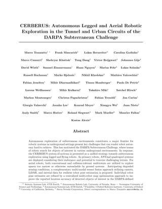
  • 11. Figure 7: Schematic system overview of the main software modules on ANYmal, specifically tailored for underground exploration missions. The components in the blue shaded area are executed on the onboard computer. The yellow rectangles are ANYmal specific modules, whereas red rectangles indicate software modules used also by the other CERBERUS’ robots. and inertial data, while Charlie further integrates thermal vision and thus provides unique localization capabilities in visually-degraded environments, as well as thermal object detection (e.g., for the survivor artifact class). To enable perception in low-light environments, all three M100 Aerial Scouts are equipped with Cree LEDs, which are synchronized with their visible light camera’s shutter producing a power-efficient flashing behavior. Figure 8: The Charlie (left) and Gagarin (right) Aerial Scouts. A second - and particularly important for our team - class of Aerial Scouts, named Gagarin, also provides a number of unique capabilities. This robot is designed to traverse narrow and visually degraded environments. Gagarin is a drone surrounded by a collision tolerant cage that allows it to sustain collisions with obstacles Alpha / Bravo Charlie Gagarin Platform DJI M100 DJI M100 Collision-tolerant platform 1-3 Camera FLIR Blackfly S FLIR Blackfly S Intel RealSense T265 Thermal N/A FLIR Tau2 N/A LiDAR Velodyne Puck LITE Ouster OS1 Ouster OS0 / OS1 IMU VectorNav VN-100 VectorNav VN-100 Integrated in autopilot Table 2: Sensor suites used in different Aerial Scouts.
  • 12. at speeds exceeding 2m/s. In order to thrive in narrow spaces, this drone has a compact design with a tightly integrated power-efficient NVIDIA TX2 board with 6 ARM CPU-cores and a 256-core NVIDIA Pascal GPU, an Ouster OS0 or OS1 (depending on the version of the Gagarin robot) LiDAR having a wide vertical FOV, an IMU and two fisheye cameras, rendering it suitable for going through staircases and vertical shafts. Additionally, to traverse visually-degraded environments, Gagarin has a custom lighting system involving LEDs at different angles designed to reduce the effect of dust on the image, increasing the visual range and enhancing the environment texture. All Aerial Scouts communicate with the Base Station using their onboard 5.8GHz WiFi radios to connect di- rectly to the Base Station antenna or through the breadcrumbs deployed by our legged robots. Importantly, as reliable high-bandwidth communication becomes increasingly infeasible in most underground environ- ments, the Aerial Scouts are able to operate completely autonomously with little to no input from the Human Supervisor, and return to their home position before their batteries become depleted. The M100 Aerial Scouts are capable of flight times of 8 to 10 minutes, while the Gagarin collision-tolerant aerial scouts present an endurance of 5 to 6 minutes. Software Architecture: The Aerial Scouts all share the same software architecture, whose basic function- alities are illustrated in Figure 9. Similar to other robots in the CERBERUS team, the Aerial Scouts use a high-level exploration path planner, described in Section 5, to plan feasible paths for the robots. The path is then tracked by a linear model predictive controller as in (Kamel et al., 2017) and the low-level command is executed by the onboard autopilot inside each robot. The odometry feedback of the robots and the map of the environment are provided by the multi-modal perception module presented in Section 6. Operator Communication Module WiFi Communication High-Level Exploration Planner Operator Requests Position Control (MPC) Multi-modal Perception Robot Autopilot Path Low-Level command Robot’s state Map NUC i7 (Alpha/Bravo/Charlie) / TX2 (Gagarin) Figure 9: Schematic system overview of the core functional modules of the aerial scouts. All the components inside the blue shaded area are executed onboard the robot. Yellow color depicts robot-specific functionalities, while red is used for software components that are unified across the CERBERUS robots. 4.3 Roving Robots Alongside the legged and aerial platforms, team CERBERUS also brought a roving robot called Armadillo into the field. This ground vehicle is complementary to the walking and flying systems presented above. System Design: Armadillo is based on the Inspectorbots Super Mega Bot (SMB) robot platform and was chosen to complement the performance of the core CERBERUS team, primarily as a means to deploy a high-gain communications antenna and due to its capability to carry large payloads and sensors. A custom- designed frame, made of lightweight aluminum extrusions, was used to house all the components on the robot. This frame was fixed atop Armadillo’s chassis and an onboard computer, namely a Zotac VR GO Backpack PC, was placed inside the protected cage-like structure. A sensor-head, attached at the highest part of the frame, houses various sensors to provide an unobstructed view of the environment. The sensor-head on the Armadillo consists of a two level design having mounting points for all the sensors of the robot. A FLIR Boson LWIR Camera and a FLIR Blackfly Color camera are mounted in the front facing configuration alongside a VectorNav VN-100 IMU. Two identical FLIR Blackfly S cameras are mounted on the sides of the sensor looking at either side of the robot. Additional FLIR Boson and Blackfly cameras are mounted in a top-facing configuration for detecting artifacts on the ceiling. A frame extension on the right side of the robot is made to mount a Robosense BPearl LiDAR Sensor that
  • 13. Figure 10: The Armadillo roving robot - a modified Inspectorbots Super Mega Bot. provides a dome-like view of the environment. At the back of the robot, a 300m-long optical fiber reel is mounted with the capability of automatic unrolling while moving. This allows wired connectivity from the Base Station to the robot. An additional 5.8GHz directional antenna is mounted in the front of Armadillo, which allows the robot to act as a network range extender, providing high-bandwidth connectivity to the Base Station. Software Architecture: The Armadillo shared the same perception architecture as the flying robots. However one significant difference is that - given its constant connectivity with the base-station through the optical fiber connection and design choices of our team - it was manually controlled by the Human Supervisor. The front facing Blackfly camera, the IMU and the Velodyne LiDAR are used for the multimodal perception as described in Section 6. The remaining sensors provide a live feed to the operator at the Base Station. 5 Exploration Autonomy The CERBERUS system-of-systems performs autonomous exploration and search for artifacts in the sub- terranean environment based on a Graph-based exploration path planner (GBPlanner) (Dang et al., 2020) that is universally designed and deployed across both legged and aerial robots. The method exploits a volu- metric representation of the incrementally updated and explored 3D occupancy map M reconstructed based on measurements from a set of onboard depth sensors {S}, as well as robot poses derived from each robot localization system {O}. In the Tunnel Circuit M was based on the work in (Hornung et al., 2013), while in the Urban Circuit the method in (Oleynikova et al., 2017) was employed. In both cases, M is using a fixed resolution, thus each voxel has an edge size rV (throughout this work this value was set to rV = 0.2m). The map consists of voxels m of three categories, namely m ∈ Mfree, m ∈ Moccupied, or m ∈ Munknown rep- resenting free, occupied, and unknown space respectively, while certain (generally disconnected) subsets of the map may correspond to “no-go” zones MNG (hereafter referred to as “geofences”) representing possible traversability constraints or other imposed limits. Let dmax be the effective range, and [FH, FV ] be the FOV in horizontal and vertical directions of each of the depth sensors S. In addition, let the robot’s configuration at time t be defined as the 3D position and heading ξt = [xt, yt, zt, ψt]. Notably, since for most range sensors perception stops at surfaces, hollow spaces or narrow pockets cannot always be explored fully. This leads to a residual map M∗,res ⊂ Munknown with volume V∗,res which is infeasible to explore given the robot’s constraints. As a result, given a volume V∗, the potential volume to be explored is V∗,explored = V∗ V∗,res. Given this representation, the planning problem is organized based on a local and a global planning bifur- cation. The overall planner architecture can be seen in Figure 11. In the local exploration planning mode, given the occupancy map M and a local subset of it ML centered around the current robot configuration ξ0, the goal is to find an admissible path σL = {ξi} in order to guide the robot towards unmapped areas and thus maximize an exploration gain ΓL E(σi), σi ∈ ΣL(set of candidate paths), primarily relating to the volume expected to be mapped if the robot traverses along σL with a sensor S. A path is admissible if it is
  • 14. collision-free in the sense of not colliding with 3D obstacles in the map and not going through geofences. Given the subspace ML the local planning problem may report that no admissible solution is interesting for the robot (zero-gain or below a set threshold). When this event, called “local completion”, occurs, the global planning mode uses the latest M representation and the current robot configuration ξ0 to identify a collision-free path σG that leads the robot towards the frontiers of the unmapped areas. Feasible paths of this global problem take into account the remaining endurance of the robot. When the environment is explored completely (“global completion”) or the battery approaches its limits, the method identifies an admissible path σH that returns the robot to its home position ξhome. The functional specifics of these two modes are outlined below. Local Planner Global Planner Best Path Shortest Paths Graph Path to Frontier Homing Path Global Graph Improved Path Best Path Path Improvement Frontiers Local Planner Global Planner Robot Speci c Software Common Local Sampling Region 1 1 F2 F1 Geofence Trigger Local Exploration Horizontal Exploration Graph Vertical Exploration Graph Figure 11: Functional diagram of the key functionalities of GBPlanner. This method bifurcates around a local and global planning mode with the first responsible for efficient exploration around the current robot location and the second responsible for re-positioning to frontiers of the explored volume in distant areas of the map, as well as auto-homing. Special functionality is provided for multi-level exploration, while the admissible paths account for collisions with 3D obstacles as well as “no-go” zones (geofences) that mark the non-traversable regions detected. 5.1 Multi-Level Local Exploration Path Planning The local planning mode of GBPlanner first iteratively builds an undirected graph GL inside the local map space ML around the current robot configuration ξ0, which will be used to derive candidate exploration paths. In the implementation of the planner, up to the Urban Circuit, the local map subset ML had a fixed cuboid size set at the beginning of the mission (details for each robot are provided in Section 10). The graph GL is built in the following manner. Given the updated occupancy map M, a bounded “local” volume VDL with dimensions DL centered around ξ0 and the respective map subset ML are first derived. Then considering a bounding box DR representing the robot’s physical size (alongside the respective map subset MR(ξ∗) for a robot state ξ∗), the planner samples a set of random configurations ξrand inside VDL and after checking which local connections (within a defined radius δ) are collision-free and outside of the geofences, builds the graph GL with its vertex and edge sets V, E respectively. Subsequently, using Dijkstra’s shortest path algorithm (Dijkstra et al., 1959), it derives paths ΣL in the graph starting from the root vertex at ξ0 and leading to all destination vertices. Given a path σi ∈ ΣL, i = 1...µ with a set of vertices νi j ∈ σi, j = 1...mi along the path (corresponding to a set of robot ξ configurations), an information gain, called VolumeGain, relating to the new volume anticipated to be explored is computed for each vertex νi j. To compute the VolumeGain at a vertex we count the number of unknown voxels inside a model of the sensor frustum (accounting for the sensor range and field-of-view) centered at the vertex. This is done by ray casting into
  • 15. the map with rays starting at the vertex. A fixed resolution of ray casting is employed. The exploration gain ΓL E(σi) for the path σi is then calculated as follows: ΓL E(σi) = e−ζZ(σi,σe) mi X j=1 VolumeGain(νi j)e−δD(νi 1,νi j ) (1) where ζ, δ > 0 are tunable factors, D(νi 1, νi j) is the cumulative Euclidean distance from vertex νi j to the root νi 1 along the path σi, and Z(σi, σe) is a similarity distance metric between the planned path as compared to a pseudo straight path σe with the same length along the currently estimated exploration direction. The heading of every planned vertex is generally aligned with the direction of the respective path segment. While legged systems are allowed to turn in place to ensure that the desired heading is reached, the aerial robots are subject to a maximum yaw rate constraint. Therefore, a reachable heading as close as possible to that of the direction of the path segment is assigned given the length of the path segment, the fixed reference velocity, and the yaw rate constraint. Importantly, this local planning stage methodology implements a specialized sub-bifurcation in its architecture to handle the case of multi-level/multi-storey environments as, for example, encountered in the SubT Challenge Urban Circuit. In this mode, the method biases its sampling of the local graph GL in order to sample densely in the vertical direction. Considering that a depth sensor unveiling relevant space is available, this offers an artificial reward of exploration gain when the robot changes “level” and thus identifies connections from the current level to the next. This motivates the robot to take a staircase or other vertical passageway connecting two storeys of the environment. In the implementation of the method as deployed up to the Urban Circuit event, it is the responsibility of the Human Supervisor to select the appropriate local exploration mode. In the case of legged robots, the path should not only be obstacle-free but also traversable. To that end, an elevation map (see Section 4.1) is utilized to check for traversability along the robot’s direction of motion, while following the planned path. The density of the elevation map is a trade-off between capturing the sur- face of the terrain accurately and keeping the computation cost to a reasonable level for onboard processing. Hence, the elevation map is calculated in a significantly smaller area than the size of the local map subset ML which is used for exploration planning. However, planning only within short distances can lead to inefficient exploration behavior. Therefore, the exploration path is calculated based on the occupancy map (specifically ML), assuming that the areas outside the elevation map are traversable, and the traversability check is done during path execution. If an area where the robot is walking towards is found to be non-traversable, the path execution is stopped, that area is marked with a geofence, and the local planner is re-triggered. This process, however, can lead to sub-optimalities as it may cause the robot to stop and re-plan when an initially unknown non-traversable region is detected which in turn can slow down the exploration. To better address this problem, longer range elevation mapping would be essential which in turn poses a set of computational and sensing challenges as discussed in Section 4.1. 5.2 Global Exploration Path Planning The global planning mode enables two critical behaviors in the exploration mission. First, upon local completion of unexplored areas, the global planning mode enables the re-positioning of the platform to unexplored areas of the map. Second, it permits autonomous homing upon reaching a critical point in the time budget of the robot. To execute these behaviors, the planner maintains a computationally lightweight global graph GG that contains vertices which potentially lead to unexplored parts of the environment called “frontier vertices”, or simply “frontiers”. A vertex is marked as a frontier if the VolumeGain of that vertex is found to be larger than a set threshold. At each local planning step, the frontier vertices from the local graph GL are extracted and the frontiers within a radius λ of any existing frontiers in the global graph are removed. The paths from the remaining frontier vertices to the root vertex of GL are extracted, clustered together according to the Dynamic Time Warping (DTW) similarity metric (Bachrach, 2013; Dang et al., 2020) and the principal path corresponding to the longest path from each cluster is retained. Finally, all the principal paths are added to the global graph, as well as admissible edges connecting them to nearby global vertices. In order to maintain a reduced list of frontiers in GG, vertices which no longer offer high gain are
  • 16. eliminated by periodically re-evaluating each frontier vertex. Additionally, at every local planning step, the planner needs to ensure that the robot has enough endurance to execute the path and return to the home location. Hence, utilizing Dijkstra’s algorithm on the global graph, the planner identifies a return-to-home path at each local planner iteration, and commands the robot to follow this path upon reaching the time budget. It is noted that the homing path queries are fast due to the sparse nature of the global graph. Choosing the best frontier to visit upon local completion is a difficult problem due to the size of the map over which the search is executed, the uncertain knowledge of these frontier vertices, as well as their true potential for exploration. Given these challenges, the selection of the frontier to visit depends on a) the time budget remaining upon reaching that frontier and b) the volumetric gain for that frontier given the time to reach it. Formally, let νG,cur be a vertex in the global graph representing the current robot configuration and F = {νF G,i}, i = 1...m be the set of updated frontiers. A Global Exploration Gain ΓG E(νF G,i) is evaluated for each frontier as follows: ΓG E(νF G,i) = T (νG,cur, νF G,i)VolumeGain(νF G,i)e−DD(νG,cur,νF G,i) (2) where T (νG,cur, νF G,i) is the estimated exploration time remaining if the planner chooses to visit the frontier νF G,i. This term is used to favor frontiers which lead to higher exploration times once they are reached. It is approximately calculated using the remaining exploration time Te(t) (based on the robot’s endurance or user-imposed mission time limit) at current instance t and the estimated time required to travel from the current vertex to that frontier, Υ(νG,cur, νF G,i), and from there to the home location, Υ(νF G,i, νG,home), as: T (νG,cur, νF G,i) = Te(t) − Υ(νG,cur, νF G,i) − Υ(νF G,i, νG,home) (3) The term D(νG,cur, νF G,i) is the shortest path length from the current vertex to the frontier, which along with the tunable parameter D penalizes longer paths. Finally, the exploration path, local or global, is further improved by modifying all vertices in the path to be further away from obstacles generating a safer path σr. The planner paths are provided to the robot-specific local planners and controllers which are responsible for their execution. 6 Multi-Modal Perception for Multi-Robot Mapping To enable robot autonomy in challenging subterranean environments, onboard perception plays a crucial role in enabling reliable robot localization and navigation. Resilient robot perception, both in terms of sensors and methods, is of particular importance for operation during the SubT Challenge as, in addition to being GPS-denied, underground environments can impose various conditions of sensor degradation due to their structural nature and operational conditions. Complete darkness, low-texture, geometric self-similarity, thermal-flatness, and the presence of obscurants (smoke, fog, dust) are some of the challenging conditions that can be encountered during the competition. Relying on any single sensing modality is unsuitable for operation in such environments, and hence, the robots of team CERBERUS utilize multi-modal sensor data from visual/thermal cameras, LiDARs, and IMUs in a complementary manner to provide reliability, robustness, and redundancy for underground robot operations. This section details the processing of the multi-modal sensor data to estimate the robot state and create a globally consistent multi-robot map. First, sensor time-synchronization and calibration are discussed. Second, the utilized complementary multi- modal fusion approach for onboard localization and mapping for individual robots is described. Finally, the deployed global multi-robot mapping approach is detailed, along with the alignment of individual robot frames B with the DARPA defined coordinate frame D, and transmission of maps to the Base Station. Figure 12 depicts the used notation with coordinate frames and provides a general overview of the deployed localization and mapping scheme. During the deployment, each robot builds and maintains an onboard map of its traversed environment. These maps are periodically sent to the Base Station mapping server,
  • 17. which combines individual robot maps and produces a globally optimized map. The self-contained onboard localization and mapping approach enables the robots to explore autonomously, i.e., a connection to the Base Station is optional. However, when connected, the global map allows, in particular, the Human Supervisor to have a combined and optimized overview of the explored environment. DARPA Gate Base Station: Global multi-robot mapping (M3RM) Mapping Server Artifact Manager Artifact Artifact detections are expressed relatively to the detecting robot Maps with pointclouds and DARPA Gate detection Onboard: Localization and mapping (CompSLAM) Global map with associated artifact locations Figure 12: Illustration of the overall localization and mapping setup with coordinate frames for each robot B1, B2 and B3. All robots align themselves with respect to a common DARPA-defined coordinate frame D using fiducial markers on the starting DARPA gate. The mapping server on the Base Station receives maps from the individual robots (blue) and combines them into a globally optimized map. Artifact detections, such as a1, are recorded relative to the robot detecting them (B3) and are sent to the artifact manager (red) for storing, additional inspection, and reporting them in coordinate frame D using the globally optimized map to the DARPA Command Post for scoring. 6.1 Time Synchronization and Calibration Precise time synchronization of the employed sensory systems is a crucial task for mapping and localization. Although the robots only move at moderate velocities, the range at which they detect visual landmarks and LiDAR points can be large. Given that small rotation changes can lead to large translations for points that lie far away from the sensor frame’s origin, small timestamp inconsistencies between angular and linear measurements can lead to significant systematic errors when distant points are observed. The Armadillo robot (during the Tunnel Circuit) and the ANYmal robots (during the Urban Circuit) employed a camera trigger board (Tschopp et al., 2020) capable of onboard synchronizing with a host computer using time translation. An integrated Kalman Filter estimates the clock-skew and offset between all sensors and the host computer. Additionally, since multi-camera systems inherently yield different exposure times for each camera, the trigger board performs exposure compensation using the mid-exposure times. Moreover, a tightly-coupled illumination board was used to trigger a set of LEDs according to the cameras’ exposure times for the flying robots and Armadillo. The LEDs are only turned on between the start of the first camera and the end of the last camera’s exposure. This makes it possible to run the LEDs at a high brightness while minimizing heat and energy consumption. For the purposes of artifact localization and detection, as well as robot localization and mapping, a number of calibrations are required. The color camera intrinsics and camera-to-IMU extrinsics were identified based on (Furgale et al., 2013). The intrinsic calibration parameters of the thermal camera were calculated using our custom designed thermal checkerboard pattern (Papachristos et al., 2018). The camera-to-LiDAR calibration
  • 18. was derived based on an implementation of the work in (Zhou et al., 2018). The Aerial Scouts operate with hardware-assisted software camera-to-IMU synchronization. While the cam- era and the IMU are free-running, the internal functionalities of the VectorNav VN-100 IMU are used to receive a synchronization pulse from the FLIR Blackfly S camera at the start of each exposure. Contained within every IMU message is the time difference between the rising edge of the synchronization pulse and the sample time of the current IMU message. IMU messages are assumed to be received in near real-time, and therefore the image timestamps are corrected based on the time difference reported by the IMU subtracted from the IMU message receive time. 6.2 Complementary Multi-Modal Localization and Mapping To enable reliable and independent robot operation in challenging environments, the robots of team CER- BERUS individually deploy an onboard complementary multi-modal localization and mapping (CompSLAM) approach (Khattak et al., 2020). This approach fuses visual and thermal imagery, LiDAR depth data, and inertial cues in a hierarchical manner and provides redundancy against cases of sensor data degradation. A schematic overview of the proposed approach is shown in Figure 13. Camera images from both visual and thermal cameras, as well as IMU measurements are fused using an Extended Kalman Filter (EKF) estimator. The deployed EKF-estimator builds on top of the work presented in (Bloesch et al., 2017), due to its low computational complexity, and extends it to concurrently operate on both visual and full-radiometric thermal images, as described in (Khattak et al., 2019; Khattak et al., 2020). To keep computational costs tractable while utilizing multi-spectral camera inputs, the Visual-Thermal- Inertial Odometry (VTIO) estimator tracks a fixed number of features in its state by balancing the share of tracked features from each image, subject to image quality using a spatial and temporal entropy eval- uation (Khattak et al., 2019). The health of the odometry estimate is evaluated by measuring covariance growth using the D-Optimality criterion (Carrillo et al., 2012). If the VTIO estimate is healthy, it is passed to the Laser Odometry (LO) and Laser Mapping (LM) modules. The LO module first independently ensures that the input estimate’s translational and rotation components are within robot motion bounds, set by the controller, before utilizing it as a full or partial motion prior for the alignment of consecutive LiDAR scans. Scan-to-scan alignment is performed by minimizing point-to-line and point-to-plane distances between ex- tracted line and plane features, similar to the work of (Zhang and Singh, 2014). The quality of scan alignment is checked by evaluating the minimum eigenvalues of the optimization Hessian matrix (Zhang et al., 2016), and ill-conditioned dimensions are replaced with VTIO estimates before propagating the LO estimate and providing it to the LM module, along with extracted scan features. The VTIO and LO modules provide estimates at the update rates of images and point clouds, respectively; in contrast, the LM module operates at half the LO module rate to remain computationally tractable. For this reason, the LM module also in- dependently evaluates input motion estimates from both modules before using them to estimate the refined robot pose in the local map using scan-to-submap alignment. Once a refined estimate is obtained, it is checked using similar health metrics in the LO step, and the final estimate is utilized for the propagation of the local robot map. 6.3 Global Multi-Robot Mapping In addition to the onboard CompSLAM, robots with an established connection to the Base Station send maps back to the mapping server, as well as artifact detections to the artifact manager. A centralized mapping server allows the Human Supervisor to view and inspect artifact detections along with a combined multi- robot representation of the environment. Generally, the global multi-modal, multi-robot mapping (M3RM) approach is based on the existing framework Maplab (Schneider et al., 2018) and divided into two parts. In the first part, each robot converts its raw sensor measurements into submaps that span consecutive time intervals. Each submap consists of a factor graph, visual descriptors, and compressed LiDAR pointclouds.
  • 19. LiDAR Mapping LiDAR Odometry Visual-Thermal Odometry Input Image Evaluation EKF Odometry Estimation Health Evaluation LiDAR IMU Thermal Camera Visible Camera External Prior Evaluation Scan Alignment Optimization Health Evaluation Odometry Estimate Propagation Input Odometry Evaluation Scan to Submap Alignment Optimization Health Evaluation Map Propagation (R,t) Features (R,t) Figure 13: Overview of the deployed complementary multi-modal localization approach (CompSLAM). The Visual-Thermal-Inertial Odometry module receives camera and IMU data and provides a motion prior to both LiDAR Odometry and LiDAR Mapping modules to perform scan-to-scan and scan-to-submap alignments respectively. Motion estimates between modules are only propagated if they pass individual health checks. These submaps are then transferred to the mapping server. Building the submaps on the robots reduces the required robot-to-mapping-server bandwidth, while only using a modest amount of computing power on each robot. The second part takes place on the mapping server and consists of combining the individual submaps into an optimized, globally consistent multi-robot map. The following subsections start by covering the submap creation and transmission approach in more detail, followed by the submap merging and global optimization strategy. Submapping and Map Transmission over Network - Each robot builds an on-robot pose graph comprising IMU, visual landmarks, and relative transformation constraints from the odometry. Furthermore, the on- robot pose graphs are divided into chunks (i.e. submaps) and are periodically sent to the Base Station to build a multi-robot map. The composed system is generally independent of each robot’s odometry estimation, i.e., the mapping system solely requires a consistent estimate of the robot’s state and the IMU biases. Specifically, during the on-robot submap building, BRISK features are detected and tracked, and at submap completion, triangulated to construct a local map using the odometry information. Consequently, this approach requires motions within a submap such that uninitialized landmarks can be triangulated. In the case of motionless submaps, which commonly occur at startup, a stationary edge connects the first and the last vertex in the pose graph to avoid optimization issues. In addition to visual landmarks, LiDAR scans are attached to the pose graph as resources using their timestamp and extrinsic calibration. The attached LiDAR scans are associated with a specific location in the pose graph and are not used for any additional computation on the robot itself but instead only on the Base Station. Submaps are created by splitting the local maps at a fixed time interval and are uniquely identified using a hash of the timestamp and robot name. To ensure consistency in the submaps when combining them at the Base Station, the first and last vertex of consecutive submaps overlap. The server additionally ensures that the last and first vertex of consecutive submaps observe the same landmarks during the combination and merges them accordingly. Before transmission, each submap is keyframed (Dymczyk et al., 2015) and serialized to disk. A synchronization service then transfers the submaps to the Base Station in a granular fashion (file-based), such that transfers can efficiently be resumed after sudden connection losses. Whenever a submap transfer is completed, the synchronization service notifies the mapping server, which in turn processes and merges the submap into the global map.
  • 20. Globally Consistent Multi-Robot Mapping - The mapping server on the Base Station periodically checks for completed submap transmissions and maintains a global map comprising all individual maps per robot. During the optimization of the global map, the mapping server utilizes different types of constraints as depicted in Figure 14. Maps from individual robots are connected by either merging visual landmarks (global visual loop closure) or performing a dense alignment between spatially close poses. Moreover, each robot Legend: Pose IMU Factors Visual Landmarks Odometry Factor Tag Alignment Dense Alignment Robot 1 Robot 2 Robot 3 Figure 14: Illustration of three multi-modal pose graphs in the Base Station’s mapping server. The graphs from individual robots are combined by co-observed landmarks or aligned pointclouds. Robot 1 and 3 detected the DARPA gate, whereas robot 2 was merged using shared landmarks. performs an alignment to the DARPA frame D by detecting AprilTags on the Starting Gate with known 3D coordinates. The camera position is found in DARPA frame coordinates by solving the perspective-n-point problem of the 2D tag detections and its result is added to the pose graph as a prior factor. Incorporating the DARPA frame alignment into the optimization has the advantage of including detection uncertainties, being more robust against outliers, and being independent of the utilized sensor system. Additionally, this facilitates the global map merging since the base frame of the robot’s map is already known. Before merging a robot’s submap into the global map, each submap is processed by itself. The submap processing performs a fixed number of operations, i.e., (i) a visual landmark quality check (ii) visual loop closure (iii) LiDAR registrations, and (iv) optimization. Since the individual submap processing is indepen- dent of other submaps, the mapping server processes up to four submaps concurrently. Furthermore, the optimizations are limited to a maximum of two minutes to ensure fast iterations. All new visual landmarks are first evaluated in terms of their distance, angle, and the number of observations. Landmarks that do not fall within the thresholds for these criteria are marked as disabled during the optimization. Next, visual-based loop closures (Lynen et al., 2015) are found using the tracked visual BRISK features and an inverted multi-index. Loop closures are handled by merging the visual landmarks in the pose graph, enabling the optimization to close loops solely using the reprojection error. Furthermore, additional LiDAR constraints are extracted by registering consecutive scans within a submap using Iterative Closest Point (ICP). The current states of the poses in the submap graph are used to determine a transformation prior for the registration. Registration results that moderately contradict the prior transformation are rejected as outliers to avoid constraints across floors or through walls. The remaining registrations are added as relative 6DoF constraints between each scan’s closest pose in the submap where the IMU is additionally utilized for interpolation between the timestamp of the scan and the pose. The optimization assumes a fixed uncertainty for each registration constraint. After the optimization, the submaps are merged into the current global multi-robot map. Similar to the submap processing, the mapping server continuously performs a set of operations on the global map, i.e., (i)
  • 21. global visual loop closure, (ii) global LiDAR registrations, and (iii) optimization. In contrast to the previous submap processing, each operation utilizes all information from each robot’s currently explored areas. Hence, the LiDAR constraints are found based on a proximity search within the global map. For each pointcloud associated with the global pose graph, a radius search is performed to retrieve spatially close registration candidates, including poses to other robots. Furthermore, all constraints resulting from LiDAR registrations are implemented as switchable constraints (Sunderhauf and Protzel, 2012). The global multi-robot map provides an overview of the explored areas to the Human Supervisor and allows the operator to command robots to unexplored regions. Last but not least, artifact detections are utilized together with the reconstructed map to query their location. When only the map onboard the robot is available, the artifact locations are directly acquired, while when the M3RM-based map is also available, then it yields optimized artifact locations. 7 Artifacts In the SubT Challenge, teams are scored by reporting the class and location of a set of artifacts to the DARPA Command Post. A fixed number of report attempts are given to each team for each Competition Course. A point is earned for each report which correctly identifies the class of an artifact and its position is within 5m of the object’s ground-truth location. Throughout both competition circuits, survivors, cell phones, and backpacks were placed alongside drills and fire extinguishers in the Tunnel Circuit, followed by CO2 (gas) sources and vents in the Urban Circuit. In this section, multi-modal artifact detection and classification are described, including the initial detection onboard the robot, as well as how the detected artifacts are attached to the global map presented in Section 6.3 such that their estimated positions can be improved using the combined measurements of all robots. 7.1 Detection and Classification Artifact detection and classification initially takes place onboard each robot. For the visible artifacts, sur- vivors, cell phones, backpacks, drills, fire extinguishers, and vents, visual artifact detection using deep learn- ing was employed. Specifically, we used YOLOv3 (Redmon and Farhadi, 2018) and its ROS porting (Bjelonic, 2018), trained on datasets featuring all DARPA-specified artifacts except CO2 gas. The training data con- sists of images from both the aerial and ground platforms, in laboratory settings against backgrounds of varying color, as well as in subterranean environments in varying lighting conditions. In addition, handheld versions of robot sensor configurations along with the on-board lighting solutions were re-created to facilitate rapid data collection and to improve viewpoint variation in the dataset. The number of images used to train each class varies from a minimum of 1915 for the cell phone, to a maximum of 3519 for the fire extinguisher. Table 3 details the number of training images used for each artifact class. Artifact Survivor Fire Extinguisher Cell Phone Drill Backpack Vent No. Images 2660 3519 1915 3084 3388 2301 Table 3: Number of images used to train YOLOv3 for each class of visible artifact. In addition to automatic detections, compressed image streams are sent back from the robots to the Base Station, where the Human Supervisor is located. Using the Operator Interface described in Section 9, the supervisor can pause and rewind these streams and manually select artifacts by clicking on the images. Given the bounding box of an automatic detection or a click from the supervisor, the interface further allows to manually add, translate, relabel and remove artifacts attached to the global map that can be reported to the DARPA Command Post.
  • 22. Due to the low precision-recall for visual cell phone detection, each robot could also detect the phone’s Bluetooth signal, and report its presence to the Human Supervisor. In the Urban Circuit, all ground systems additionally integrated a Sensirion SCD30 CO2 sensor to detect the gas artifact, reporting the position above which the CO2 concentration had passed some threshold. 7.2 Map Attachment The attachment of artifacts to the global map is performed in two steps. The first step takes place onboard and consists of filtering the artifact detections to determine the artifact’s position in the robot’s local coor- dinate frame. Referring to Figure 12, we denote the estimated position of the jth artifact in the body frame of the robot which detected it with B aj. In the second step, an artifact report is transferred to the mapping server, where it is attached to the pose graph and its optimized position in the DARPA frame D aj,opt can be computed. Due to the possibility of false positives and to prevent continuous artifact detections from saturating the robot’s network connection to the Base Station, detections are first cast into the robot’s map, and then filtered before being sent to the Base Station, providing the Human Supervisor with only high confidence detections. Specifically, the bounding box containing the detected object in the image plane is divided into a grid of pixels. These pixels are converted into rays using the camera model and the robot’s extrinsic calibration parameters. Casting these rays into M results in a set of points that include points on the object, as well as other surfaces contained within the bounding box. To approximate the object’s true position, the median point is selected as the measured artifact position. To filter both multiple class detections and refine the estimate of the artifact’s position aj, a sphere with radius Ra is drawn at the initial estimate of aj. Additional detections whose projected positions lie within this sphere are considered to be detections of the same object. For each sphere, separate binary Bayes filters for each artifact class are recursively updated to estimate the probability that the sphere contains an object of a given class, and the sphere’s center aj is further updated as the average position of all detections projected into the sphere. Once the probability of any one class exceeds a predefined threshold, the artifact’s detection is considered “confirmed”. A summarized detection report is sent to the Human Supervisor alongside a representative image of the artifact, and the corresponding sphere is frozen to prevent any additional detections and subsequent duplicate reports. This process is depicted in Figure 15. Despite effort for automated localization of the cell phone’s position via a sequence of pose-annotated Bluetooth-based detections and tracking of their RSSI values, it was determined that the most reliable method would be to notify the Human Supervisor of the robot pose at which RSSI values of a cell phone were detected. The supervisor could then improve the cell phone’s position by moving a marker on the map or by drawing a bounding box around the cell phone in the camera images. In case the latter option was used, the bounding box would be sent back to the robot, which would then convert it to a 3D artifact position aj using the method described in the previous paragraph. In the Urban Circuit, this same approach was used to determine the gas artifact positions. Figure 15: Illustration of the process of casting automatic detections into the map. a) Shows the detection of a backpack artifact with the image frame in blue, and the bounding box in green. b) The bounding box is divided into a fixed grid. c) A ray from each grid cell is cast from the image plane until it intersects a surface. d) The median ray, in red, is selected and a sphere of radius Ra, in orange, is placed in the map. e) Subsequent rays from additional detections along the path shown in pink, which land within the sphere, increase the confidence of the artifact category until reaching a threshold.
  • 23. The artifact reports sent from the robot to the mapping server consist of the artifact’s type, the timestamp ti at which it was “confirmed” and the artifact’s filtered position in the robot’s local frame Bti aj. The annotated camera image in which the artifact was detected at time ti is also included to provide additional context to the Human Supervisor. Once received by the mapping server, the artifact report is attached to the pose graph node TDBti that corresponds to the pose of the robot’s body in the DARPA frame D at timestamp ti. The artifact’s most recent optimized position can then be computed as D aj,opt = TDBti ,opt Bti aj. When desired, the artifact’s unoptimized position can also be recovered with D aj,unopt = TDBti ,unopt Bti aj. 8 Networking During mission deployments, all robots communicate with the Base Station via an ad hoc wireless network to share mapping data, artifact locations, and other information. This network operates in the 5.8GHz range and is progressively built by the robots that can communicate with each other and extend the network by dropping additional WiFi nodes. This section describes the hardware and software configuration that enables remote networking of the agents in the underground. Figure 16 shows an overview of the communication architecture used by team CERBERUS. Figure 16: Block-diagram view of the networking infrastructure used during the Tunnel and Urban Circuits. Roving and quadrupedal robots, as well as dropped communication nodes, create an ad hoc mesh network, which establishes the backbone communication infrastructure. The roving robot was also equipped with a fiber optical cable to maintain connection to the Base Station. Aerial scouts used a standard (802.11) WiFi network, created either by a directional antenna at the Base Station or by a dropped breadcrumb. 8.1 Mobile Agent Nodes Agents employ two different hardware methods. Ground robots are equipped with a commercial off-the-shelf device (ACKSYS Communications Systems - EmbedAir1000) that supports WiFi access point, client, repeater, and MESH point modes. In mesh mode, these devices create a mesh network, that is a local network topology in which the infrastructure nodes connect directly, dynamically and non-hierarchically to as many other nodes as possible and cooperate with one another to efficiently route data from/to clients. In this way, ground robots establish a backbone wireless network shared among the other agents. Due to their limited payload capability and size constraints, the aerial robots did not carry mesh node-capable devices and acted solely as clients. They connect to the closest existing wireless access point, broadcast either by the Base Station or by nodes deployed by ground robots.
  • 24. 8.2 Base Station Network In preparation for a wide variety of competition scenarios, the team prepared four solutions to provide communications from the Base Station into the subterranean environment. First, the Base Station uses an ACKSYS EmbedAir1000 WiFi radio and connects to the mesh network using a high gain, directional panel antenna from L-Comm; supplying a high bandwidth connection both within the Staging Area as well as deep into the competition area. Second, Armadillo was deployed with a 300m-long optical fiber cable, a panel antenna, as well as a multi-modal perception system that further allowed it to be remotely controlled by the Human Supervisor while extending the WiFi network around corners and down corridors with ease in relative proximity to the Base Station. Third, a panel antenna was attached to a PVC pole and angled to provide a network down a stairway very near the competition gate. The pole was manually extended and oriented down the stairway by a team member. Finally, an EmbedAir1000 WiFi radio and its battery were placed in a foam ball which was manually thrown by a team member down a stairway to provide a network connection to the lower level of the circuit. The Gagarin Aerial Scout utilized both the ball and pole antennas while exploring the staircase. 8.3 Deployable Mesh Nodes ANYmal robots were able to carry additional WiFi nodes and deploy them on the ground to expand the reach of the wireless mesh network incrementally. Each robot was able to store four modules inside its belly plate and release them by lowering the torso height and activating the payload release mechanism described in Section 4.1. Each node is a water and dustproof self contained unit, consisting of a battery pack (allowing approximately two hours of operation), a battery management system, a magnetic switch (to switch the module on after releasing it), an LED to aid the recovery of the module after the mission, two WiFi patch antennas, and an EmbedAir1000 module (see Figure 5). In as ideal as possible underground conditions, such as a straight tunnel, the modules can reliably communicate within a range of 100 m when dropped on the ground. However, due to obstructed lines of sight from solid material (e.g., in a mine corner), multipath and reflections in underground settings, performance may vary considerably. As evaluated via experimental observations, close to the first communication module a maximum available bandwidth of approximately 200Mbps was observed. In team deployments, the legged robots and the droppable communication nodes had both radios of the EmbedAir1000 module enabled to maximize the communication performance and maintain as much of the initial bandwidth as possible across the deployed communication topology. The Human Supervisor was left in charge of deciding the deployment location, as wireless signal propagation is often unpredictable in subterranean scenarios. (Rizzo et al., 2013) show that a deviation in robot trajectory of a few centimeters can cause a significant difference in terms of received power on its onboard mesh receiver. In a more recent analysis, (Tardioli et al., 2019) show that due to destructive self-interference of signals reflecting off tunnel walls, there is a highly varying fading effect which leads to Received Signal Strength Indication (RSSI) having a variance of up to 30 − 40%. As a result, RSSI can be a misleading indicator to check the quality of a wireless connection inside a tunnel. Moreover, this variance can result in a link between two nearby mesh nodes reporting a worse signal strength than between nodes further apart. These peculiar characteristics, therefore, make an automatic decision of where to deploy mesh nodes a non-trivial problem. As a result, the deployment location was decided by the Human Supervisor. This decision was based on information about signal quality (such as the output of ping utility) between the Base Station and the agent, as well as considerations about the geometry of the environment surrounding the robot. 8.4 Nimbro - Multi-Master Network The Robot Operating System (ROS) was used as middleware for message passing to enable communication between processes running on each robot, as well as across robots on the same network. However, ROS requires a rosmaster process which monitors all communication connections. There can only be one ros- master on a given network and typically, this process is run onboard a robot’s computer in case there is
  • 25. communication loss with the Base Station. This presents a challenge in scenarios with multiple robots, each with their own rosmaster, communicating on the same network to the same Base Station. The Nimbro Network1 software package allows the generic transport of ROS topics and services over unreli- able network connections and has been deployed in several robotic challenges (Stückler et al., 2016; Schwarz et al., 2017). Since it avoids any configuration/discovery handshake, it is suited for situations like the SubT Challenge where wireless connections can drop and recover unexpectedly. Its primary purposes are to de- couple multiple rosmasters and select which data are transmitted between agents and the Base Station. A hardcoded list of data to be exchanged may be cumbersome to maintain and adapt, especially when tools such as multimaster fkie (Tiderko et al., 2016) offer the possibility to automatically establish and manage a multi-master network with little or no configuration. However, these automatic tools require extra cus- tomization to be adapted to the SubT Challenge, as done by team CoSTAR (Queralta et al., 2020) and may be error-prone, transmitting unnecessary data and using limited bandwidth. Therefore, given that an ANYmal robot had more than 800 topics and 400 services in its ROS system, the alternative to clearly identify which data streams should be transmitted and not rely on any automatic decision was preferred. A key factor in a system with multiple rosmasters is time synchronization between the agents and the Base Station. This was achieved through the usage of the software tool chrony2 . chrony is an implementation of the Network Time Protocol (NTP) that can synchronize the system clock with a predefined server. In this use case scenario, each robot acted as a client of the Base Station, which was the main NTP server. 9 Operator Interface A crucial aspect of the SubT Challenge is the single Human Supervisor at the Base Station. This person is the only individual allowed to coordinate, manage, and monitor the deployed systems. The single operator requirement is intended to minimize the amount of human intervention for this type of autonomous mission and forces the robots to have a high level of autonomy, while remotely mapping and/or navigating complex environments. During the Tunnel and Urban Circuits, the Human Supervisor used a custom and integrated solution for the Base Station setup (see Figure 17). This solution was composed of a sturdy box (Peli Air Case - Pelican) containing electronic components (WiFi router, auxiliary screen, etc.). It ensured fast deployment and setup of the Base Station. The supervisor used two main software modules to interact with the deployed robots: a Mission Control Interface (MCI), and an Artifacts Reporting Interface (ARI), exposed through a Graphical User Interface (GUI) (see Figure 18). The MCI was used to (a) check the status of each agent, (b) give high-level commands to override the current robot’s behavior and (c) request specific sensor data to evaluate the current situation better. The ARI was used by the Human Supervisor to (a) have a top-down view of the global map created during the mission, (b) visualize throttled and compressed image streams from the agents, to manually report artifacts, and to (c) check, and approve or discard artifacts that were automatically detected by the robots. Team CERBERUS adapted its approach towards the single Human Supervisor requirement between the Tunnel and Urban Circuits, improving the GUIs to control multiple agents, as well as the amount of ex- changed data between robots and the Base Station. Major changes to the communication architecture were introduced. These are highlighted in the following sections. 9.1 Robot Control During the Tunnel Circuit, each robot received commands from the Human Supervisor via a dedicated Operator’s PC (OPC). An OPC was specifically set up to interact with one or more robots. It used the 1https://github.com/AIS-Bonn/nimbro_network 2https://chrony.tuxfamily.org/
  • 26. (a) Base Station. (b) Tunnel Circuit setup. (c) Urban Circuit setup. Figure 17: Setup of the Base Station for the Human Supervisor. Operator’s box with external screen and docking station (a). Setup for Tunnel Circuit: one PC for aerial robots, two PCs to control two ANYmal robots, one PC for the Armadillo rover, and the main ARI running on the screen of another PC (b). Setup for Urban Circuit: one PC for aerial robots, one PC to control all ground robots, and the main ARI running on the screen of another PC (c). rosmaster of the corresponding robot and was used to initialize the agent (launching procedure, detection of the DARPA gate, etc.). Every ground robot operated in conjunction with its own OPC, and could stream all requested topics to the supervisor. On the other hand, all the aerial scouts could be controlled - one at a time - by another OPC. Each of these OPCs run its own instance of MCI, customized based on the type of robot. Only Aerial Scouts took advantage of the multi-master architecture with the Nimbro Network software package (described in Section 8.4), whereas ground robots used it only to report artifacts and map updates. Once each robot was set up by the Pit Crew and ready to start the mission, its OPC was passed to the Human Supervisor that could then use it to deploy the robot. The described setup resulted in an extra burden for the single Human Supervisor who had to deal with multiple PCs to execute the mission. For example, to control two ANYmals, one wheeled ground robot and aerial robots, the supervisor had to deal with four different OPCs, plus the additional PC running ARI - see example setup in Figure 17b. This approach was not sustainable, and therefore specific modifications were applied for the Urban Circuit. A different setup of the Base Station and for controlling the robots was employed during the Urban Circuit. Every robot leveraged the multi-master architecture with the Nimbro Network package and exported only a subset of the ROS topics and services to its MCI. This prevented the wireless network from being cluttered with data that was not strictly needed for the mission execution. Moreover, the concept of “on-demand” topics was introduced: sensor data such as LiDAR scans and elevation maps require a considerable amount of bandwidth to be streamed over WiFi, and are most of the time not necessary to be continuously sent to the Human Supervisor. Therefore a single message of these data streams was sent only upon request of the supervisor via the MCI. Each robot still had its dedicated OPC, but it was used solely for agent setup by the Pit Crew prior to the deployment. The overall startup procedure included one PC to run the instances of MCIs for all ground robots, and one other for the MCI for aerial robots. This meant that to control two ANYmals, the Armadillo rover and the aerial scouts, the Human Supervisor had to deal with two computers, located at the Base Station (see Figure 17c). In both Circuits, the Human Supervisor was able to supervise the decisions taken by each agent and, if required, decide to re-define the exploration bounding box in which each robot was allowed to explore. In every assigned area as defined by the planner bounding box, each robot was exploring the unknown space autonomously without relying on external information. If necessary, the Human Supervisor was able to overrule the autonomous planner and provide way-points to any robot. 9.2 Artifact Reporting The artifact reporting interface (see Figure 18c) is designed to reduce the strain on the Human Supervisor while improving situational awareness and reducing the chance of reporting mistakes. It is composed of panels showing video streams from the selected robots, a panel notifying the supervisor of all new automatic
  • 27. (a) ANYmal MCI. (b) Aerial Scout MCI. (c) ARI Figure 18: Mission Control Interfaces (MCI) for ANYmal (a) and aerial scouts (b). They have a similar layout but feature some customization based on the specific type of robot. The minimal amount of data displayed to the Human Supervisor reflects the need to reduce streamed data from each robot to the essential ones: a frame representing the robot’s pose in the map, requested LiDAR scans and/or elevation map snapshot, information about automatically detected artifacts and their location. The Artifact Reporting Interface (ARI) combines video streams from all robots, a panel to accept and modify artifact detections, and an overview of the reported global dense map overlaid with the state of all detected artifacts (c). artifact detections, an RViz window showing all detected artifacts in the global dense map, and a text window for important system errors. The video streams can be paused and rewound, allowing the supervisor to better understand the areas explored by the robots. In case some artifacts were not detected automatically by the robots, a bounding box can be drawn on the image to attach the artifact to the map as discussed in section 7.2. When the Human Supervisor is notified of a new automatic artifact detection, the associated camera image, annotated with the artifact’s bounding box and class, is shown for context. Under normal operation, the supervisor would accept the artifact, which would then be added to the multi-robot global map. As a fallback, the supervisor is also able to bypass the automatic artifact type detection and mapping server and file artifact reports directly to the DARPA Command Post. Once an artifact has been added to the multi-robot global map, it appears in an RViz panel together with the optimized global dense map. For additional context, the artifact’s original position, optimized position, and the robot pose from which it was observed are shown. Interactive markers are used to allow the Human Supervisor to report, modify, and delete artifacts through a right-click menu. Whenever an artifact is selected, its associated annotated camera image is shown in a dock next to the map. This proved very helpful for the supervisor to recall and distinguish artifacts. Once an artifact is reported, its color changes from cyan (not yet reported) to green (valid) or red (invalid) depending on the response from the DARPA Command Post. As the robots explore the environment further, the global map improves due to additional measurements, including loop closures. When significant improvements occur, the Human Supervisor can submit new reports for artifacts that were initially rejected. 9.3 Fallback Solutions Given the centralized nature of the reporting architecture, special care is taken to minimize the damage to the team’s competition score in case of system malfunctions on the Human Supervisor’s PC at the Base Station. Starting at the hardware level, a custom-built server is used as the Operator PC. To provide robustness to temporary power losses, it is powered through an Uninterruptible Power Supply. At the software level, all packages are designed such that they can be started independently and at any point in time. The packages that cannot be implemented in a stateless fashion continuously save backups of their internal state to persistent storage. As an example, all the artifact positions received at the Base Station are periodically saved to disk. All packages can, therefore, safely be relaunched at any time, either by the Human Supervisor or automatically if crashes are detected. The primary reliability concept for the multi-robot global map is to combine measurements from comple-