SlideShare a Scribd company logo
1 of 6
Download to read offline
ISSN (e): 2250 – 3005 || Vol, 04 || Issue, 5 || May – 2014 ||
International Journal of Computational Engineering Research (IJCER)
www.ijceronline.com Open Access Journal Page 25
Robotics Helicopter Control and its Applications in Engineering
Prof.Dr.Eng.PVL Narayana Rao1
, Mr.Jemal Ahmed Andeta2
,
Mr.Habte Lejebo Leka3
, Mr.AbrahamAssefa Simmani4,
Er.Pothireddy Siva Abhilash5
1
Professor of Computer Science Engineering, Dept. of Information System, College of Computing &
Informatics, Wolkite University, Ethiopia
2
Dean of the College of Computing and Informatics, Wolkite University, Ethiopia
3
Head of the Dept. of Information Systems, Wolkite University, Ethiopia
4
Head of the Dept. of Information Technology, Wolkite University, Ethiopia
5
SoftwareEngineer, Staffordshire University, Staffordshire, United Kingdom
I. INTRODUCTION
Our experimental test bed (Figure 1) is composed of a robot helicopter and two mobile ground robots
thus making it a morphologically heterogeneous group. The advantages of using a group of robots to execute
coordinated activity have been discussed extensively in the literature. However heterogeneous groups typically
involve higher overhead in terms of system maintenance and design.The USC Robotics Research Laboratory
designed a heterogeneous group consists of a robot helicopter and several mobile robots for inspection and
observation applications.
Figure 1: The experimental testbed consisting of the AVATAI (Autonomous Vehicle Aerial Tracking and
Inspection) robot helicopter and two Pioneer AT mobile robots.
ABSTRACT
The Robot assembly comprises of one robot helicopter and two unmanned ground vehicles, they are AT
Robots. The AVATAI (Aerial Vehicle Autonomous Tracking andInspection) is based upon the Bergen
Industrial RC model helicopter. The following sensors/electronics are onboard all robots; GPS, color
CCD camera, wireless video and embedded PC/104 boards running QNX (a realtime OS). Wireless
Ethernet provides a 2.0 Mbps multiway communication link between all robots and the operator. The
AVATAI also has an Inertial Navigation System and the Pioneers have seven ultrasound sensors for
obstacle detection. The helicopter is controlled partly by the onboard control system and in part by a
human pilot. The Pioneers are fully autonomous. To date we have demonstrated 1) High-level tasking
by a human operator of the robot group to cooperatively patrol a designated area and 2) Automatic
retasking of the robots by simulated "alarms" on the area perimeter. The robots navigate to the alarm
scene to provide live video while maintaining basic patrolling functionality.
KEY WORDS: GPS, AVATAI, Pioneer, OCU, QNX, Navigation System
Robotics Helicopter Control and its Applications in Engineering
www.ijceronline.com Open Access Journal Page 26
In the work described here, we focus on an experimental task motivated by an application where a
single person has control and tasks the robot group at a high level. A possible application is alarmed with
security in urban areas where a single guard would need to control and monitor several (possibly heterogeneous)
robots. In the application described here the robot group patrols an outdoor open area (a few obstacles are
present on the ground) defined by a perimeter. The boundary is defined by a set of vertices (in GPS coordinates)
which when connected by line segments form the boundary of a closed convex irregular polygon. In the work
reported here the robot helicopter is flown by a human pilot for purposes of safety and speed. However we rely
on a human pilot to transition from a stable hover at one point in space to another. Both ground robots are fully
autonomous in the experiments reported here.
The robots in the experiments cover the area bounded by the perimeter and send imagery back to a
human operator via a wireless video downlink. The operator is able to set high level goals for the ground robots.
An example of a high level goal is “follow the helicopter.” If a particular ground robot is given this high level
goal it will stop patrolling and will follow the helicopter as it moves. The motivation behind this is to allow the
ground robots to “take a closer look” at areas which the operator finds interesting based on aerial imagery. The
operator can designate points of interest within the perimeter which serve as area markers for robots to
periodically explore. The basic idea behind the implementation of the control programs is however to achieve
robust functionality without explicit top-down planning. Rather the overall behavior of the group is the result of
interacting control systems that run on the individual robots which essentially allow each robot a high degree of
autonomy.
II. HARDWARE AND SOFTWARE DESCRIPTION
2.1 AVATAI Hardware
The current AVATAI, shown in Figure 1, is based upon the Bergen Industrial Helicopter, a radio
controlled (RC) model helicopter. It has a two meter diameter main rotor, is powered by a 4.0 horsepower twin
cylinder gas engine and has a payload capability of approximately 10 kilograms. The helicopter has five
degrees of control: main rotor lateral and longitudinal cyclic pitch, tail rotorpitch, main rotor collective pitch and
engine throttle. The first three control the roll, pitch and yaw of the helicopter while the last two control its
thrust. The helicopter can be controlled by a humanpilot using a hand held transmitter which relays pilot control
inputs to an onboard radio receiver using the 72 MHz frequency band. The receiver is connected to five
actuators, one for each degree of control on the helicopter. For autonomous operation, these pilot control inputs
are replaced by computer generated control inputs. A block diagram of the AVATAI system; including sensors,
onboard and off board computing resources, wireless communication links and electrical power sources, is
given in Figure 2. A variety of sensors are mounted on the AVATAI that provide information about the state of
the helicopter as well as the environment in which it operates. An integrated Global Positioning System/Inertial
Navigation System (GPS/INS) device, consisting of a GPS receiver and an Inertial Measurement Unit (IMU), is
the primary sensor used for low-level control of the helicopter. The GPS/INS provides position (latitude,
longitude and altitude), velocity (horizontal and vertical), attitude (roll and pitch), heading (yaw), delta theta and
delta velocity information. This particular GPS receiver can only track 4 satellites at once and consequently
provides a relatively poor estimate of current latitude and longitude as compared to other available receivers.
So, a second standalone GPS receiver is used that can track up to 12 satellites at once.
This improves the standard deviations of the estimates of latitude and longitude from 4.5 meters for the
4-channel GPS unit down to 20 centimeters for the 12-channel unit. This GPS receiver is used for the high-level
(guidance and navigation) control of the helicopter. A downward facing ultrasonic (sonar) transducer provides
altitude information and a RPM sensor mounted on the main rotor mast measures engine speed. A downward
looking color CCD camera provides visual information of the area below the AVATAI.
Robotics Helicopter Control and its Applications in Engineering
www.ijceronline.com Open Access Journal Page 27
Figure 2: AVATAI system block diagram
Onboard computing needs are met using a number of commercial off the shelf (COTS) PC/104 boards
and one additional custom built PC/104 board. The main processor board contains a 486DX4 CPU which runs at
133 MHz, has 16 Mbytes of RAM and 40 Mbytes of solid state disk on chip (DOC). The DOC contains both the
realtime operating system (RTOS) and flight software. The 486DX4 boots up the RTOS at system power up,
executes all flight control and image processing software and provides an interface to other PC/104 boards.
These boards include a timer/counter board used both to generate actuator commands and read pilot commands,
a custom built PC/104 board that allows switching between human generated and robot generated commands on
an actuator by actuator basis as well as acting as an interface to the RPM sensor and sonar, a serial port board
for interfacing to the GPS/INS and standalone GPS, a color video frame grabber for the CCD camera and a
PC/104 to PCMCIA interface board to allow the use of PCMCIA cards onboard the AVATAI. A 2.4 GHz
wireless Ethernet PCMCIA card provides a multiway 2.0 Mbps communication link between the AVATAI,
other robots and a human using an operator control unit (OCU). (The OCU comprises the off board computing
resources and will be described in detail later). The human receives grabbed video frame information and other
telemetry from the AVATAI and sends high-level tasking commands to the AVATAI via this link. In addition,
differential GPS corrections are sent from the OCU to the GPS receivers onboard the AVATAI through the
wireless Ethernet to improve the GPS performance. A live video feed, provided by a one way 1.3 GHz wireless
video link from the CCD camera, is displayed on a monitor. Nickel-metal hydride (NiMH) and lithium-ion (Li-
Ion) batteries supply power to the electronics. The GPS/INS is relatively power hungry, requiring 0.8 amps at
+24 volts and so a dedicated 12-volt, 3.5 amp-hour NiMH battery is connected to a DC/DC converter to produce
+24 volt power. The electronics can operate for roughly an hour with this battery supply. Mission length is
limited by the flight time of the helicopter on a single tank of gasoline, which is approximately 30 minutes in
duration.
2.2 AVATAI Software
The operating system used is QNX; a UNIX-like, hard real time, multitasking, extensible POSIX
RTOS with a small, robust microkernel ideal for embedded systems. The flight software encompasses all
remaining software running onboard the AVATAI. This currently includes (or is planned to include):
1. low-level software drivers for interfacing with sensors and actuators
2. Flight control software for guidance, navigation, and control.
3. learning software
4. self-test software including built in test (BIT) and health checks software for increasing robot fault
tolerance
5. vision processing software running on the frame grabber
Robotics Helicopter Control and its Applications in Engineering
www.ijceronline.com Open Access Journal Page 28
Figure 3: Pioneer system block diagram
All software is written primarily in C/C++, with assembly used only when required for speed of
execution. Custom drivers have been written for the timer/counter card, the GPS/INS and GPS units, the frame
grabber and the wireless Ethernet PCMCIA card. The remaining software is still under development.
2.3 Pioneer Hardware
The Pioneer AT robots used in this work is identical to each other. Each robot is four-wheeled base
with skid steering. The wheels on the left are coupled mechanically as are the wheels on the right resulting in
two degrees of freedom in the drive. Turning is accomplished by a speed differential between the left and right
sides. Each robot has a Lithium-Ion (Li-Ion) battery pack (Two 10.8 volt, 4.05 amp-hour Li-Ion) for the
electronics. The motors are powered by a lead acid battery that allows up to 4 hours of operation on hard
surfaces and approximately one hour on grass. Each robot is equipped with a ring of seven front looking sonars
which are controlled by a low-level Motorola 6811 microcontroller. The wheel speeds are available through
encoders. The low-level 6811 board is connected to a PC/104 stack via a serial connection. The Pioneer also has
a vision system comprised of a camera on a pan-tilt head controlled by a Motorola 68332 board running the
Congnachrome color vision system. The main PC/104 processor board contains a 486DX4 133MHz CPU, 4
Mbytes of RAM and 40 Mbytes of solid state disk on chip which contains both the real time operating system
(RTOS) and control software. Each robot is equipped with a NovaTel GPS system connected to the PC/104
processor via a serial port. Additional sensors include a compass and a gyroscope. The gyroscope is connected
to a A/D card on the PC/104 stack. A 2.4 GHz wireless Ethernet PCMCIA card provides a multiway 2.0 Mbps
communication link between each Pioneer and the other robots. A live video feed, provided by a one-way 2.3
GHz wireless video link from the CCD camera, is displayed on a monitor. A block diagram of the Pioneer
hardware is given in Figure 3.
2.4 Pioneer Software
The control system for the Pioneer AT (described in the next section) is all written in C and runs under
QNX on the PC/104 stack described above. The software includes
1. Low-level software drivers for interfacing with sensors specifically software for the wireless Ethernet driver
and the GPS driver.
2. control software for obstacle detection and avoidance, navigation and mapping
2.5 OCU Hardware
The operator control unit is implemented using a Toshiba Tecra 510CDT laptop PC based upon a 133
MHz Pentium CPU. It has 144 Mbytes of RAM, a 4.3 Gbyte hard drive, a 12.1 inch high-res color monitor, a
CD-ROM and an Ethernet connection. The QNX operating system is installed as well as the Watcom C/C++
compiler. A docking station expands the capabilities of the laptop by providing two full-length expansion slots
for standard ISA and 32-bit PC Expansion Cards and onehalf-length 32-bit PC expansion slot. It also has a
selectable bay for installing additional hardware such as CD-ROM drives or floppy drives. A 1.44M byte
floppy drive has been installed in the slot.The 510CDT has multiple functions and is used during all phases of
the project; including development, integration and test. The primary purpose of the laptop is to function as a
wireless OCU for communication and tasking of the robots. A 2.4 GHz wireless Ethernet device is connected to
the Toshiba, providing a multiway connection between the human at the OCU and the wireless PCMCIA cards
Robotics Helicopter Control and its Applications in Engineering
www.ijceronline.com Open Access Journal Page 29
onboard the robots. Additional functions of the 510CDT include the following: First, it provides a software
development environment through the use of the QNX operating system and the Watcom C/C++ Compiler.
Using this environment code is developed and tested. Also, using RCS, a QNX software version control utility,
software configuration management is implemented. Second, the 4.3 Gbyte hard drivesprovide long-term
storage capability for mission data. Third, the docking station provides an ISA slot for a GPS receiver used to
produce differential GPS corrections for use by the mobile robots.
III. USER INTERFACE
The user interface for the system is implemented under QNX using the Phab GUI development system.
The basic layout of the interface is deliberately kept simple so as to allow an inexperienced operator to quickly
learn how to use it. A screenshot of the interface is shown in Figure 4. The user interface allows the operator to
examine telemetry from any robot, task individual robots to do specific activities (such as following, patrolling
etc.) and monitor the location of the robots in a 2D plan view. In addition, TV monitors show the operator a live
wireless video feed from each of the individual robots. Tasking is done by selecting a robot with the mouse and
clicking on one of the tasks available in the form of the task list popup menu.
Figure 4: A screenshot of the user interface
IV. RESULTS WITH TEST TASKS
The system described here has been tested with two simple tasks to date. The operator initializes the
system with a set of GPS coordinates that define the perimeter of interest. The robot locations are registered to a
common coordinate frame which is displayed to the operator on the user interface. The first task used for testing
was a cooperative patrolling activity by the robots. The helicopter was flown by the human pilot and the Pioneer
ground vehicles followed it on the ground using GPS. The only input from the operator is at the start of the task.
When the helicopter is fully autonomous we expect to be able to load a flight plan into it (in the form of several
via points) and have the rest of the robots follow in loose formation.
The second task we have used for testing involves the automatic retasking of the robots by simulated
"alarms" on the area perimeter. The robots navigate to the alarm scene to provide live video while maintaining
basic patrolling functionality. When an alarm goes off (alarms are simulated by user keyboard input to the
system), the robot nearest to the alarm disengages the patrolling behavior and navigates to the site of the alarm.
Since this is a reconnaissance style scenario the robot simply returns a close-up view of the scene of the alarm to
the operator in the form of a live video feed. The other robot continues patrolling.A detailed analysis of the
behavior of the group as a whole is the subject of a forthcoming paper [Sukhatme 99]. Videotapes of the system
are available at http://robotics.usc.edu/brochure/afv.html.
Robotics Helicopter Control and its Applications in Engineering
www.ijceronline.com Open Access Journal Page 30
REFERENCES
[1] Amidi, O. (1996), An Autonomous Vision-Guided Helicopter, PhD thesis, Department of Electrical and Computer Engineering,
Carnegie Mellon University.
[2] Arbib, M.A. (1995), Schema theory, in M.Arbib, ed., `The Handbook of Brain Theory and Neural Networks', MIT Press, Cambridge,
MA, pp.830--834.
[3] Arkin, R.C. (1990), `Integrating behavioral, perceptual, and world knowledge in reactive navigation', Robotics and Autonomous
Systems 6,105--122.
[4] Arkin, R.C. (1992), `Cooperation without communication: Multiagent schema based robot navigation', Journal of Robotic Systems.
[5] Arkin, R.C. (1998), Behavior-Based Robotics, The MIT Press, Cambridge, MA.
[6] Brooks, R.A. (1986), `A robust layered control system for a mobile robot', IEEE Journal Robotics and Automation 2(1),14--23.
[6] Cavalcante, C., Cardoso, J., Ramos, J. J.G. & Neves, O.R. (1995), Design and tuning of a helicopter fuzzy controller, in `Proceedings
of 1995 IEEE International Conference on Fuzzy Systems', Vol.3, pp.1549--1554.
[7] DeBitetto, P., Johnson, E.N., Lanzilotta, E., Trott, C. & Bosse, M. (1996), The 1996 MIT/Boston University/Draper Laboratory
autonomous helicopter system, in `Proceedings of 1996 Association for Unmanned Vehicle Systems 23rd Annual Technical
Symposium and Exhibition', Orlando, pp.911--920.
[8] Dedeoglu, G., Mataric, M. & Sukhatme, G.S. (1999), Cooperative robot mapping, in `Proceedings of the 1999 SPIE Conference'.
[9] Fukuda, T., Nadagawa, S., Kawauchi, Y. & Buss, M. (1989), Structure decision for self-organizing robots based on cell structures -
cebot, in `IEEE International Conference on Robotics and Automation', IEEE Computer Society Press, Los Alamitos, CA, Scottsdale,
Arizona, pp.695--700.
V. BIOGRAPHIES
P.V.L. NARAYANA RAOwas born in Vijayawada, Krishna District, Andhra Pradesh, India. He completed
M.Tech. from Sam Higginbottom Institute of Agriculture, Technology and Sciences Deemed University (
Formerly Allahabad Agricultural Institute),UP, India and PhD in Computer Science Engineering from
Lingaya’s University, Faridabad, Haryana State, India. He has 8 years of National Teachingexperience in
reputed India Post Graduation Engineering Colleges, 14 years of International Teaching experience in different
Universities of Foreign Country Ethiopia, East Africa and 4 years National Industrial Experience in India as a
System Analyst, Systems Developer. He iscurrently working as Professor (CSE), Wolkite University, SNNPR,
P.O.Box No.7, Wolkite, Ethiopia, and East Africa. He is a member of various professionalsocieties
likeWASET, USA, IAEng, Hongkog and CSE, Ethiopia. He has various publications in theNational and
International Journals.
JEMAL AHMEDANDETAwas born in Arekite, SNNPR, Ethiopia, and East Africa. He completed his
graduation in Information Science from Haremaya University, Ethiopia, East Africa and presently working as
the Dean of the college of Computing and Informatics in Wolkite University, Wolkite, Ethiopia.
HABTE LEJEBOLEKA was born in Arba Minch, SNNPR, Ethiopia, and East Africa. He completed his
graduation in Information System from Addis Ababa University, Ethiopia and now he is working as Head of the
Department of Information System in Wolkite University, Wolkite, Ethiopia.
ABRAHAM ASSEFA SIMMANI was born in Wolkite, SNNPR, Ethiopia, and East Africa. He completed his
graduation in Information Technology from Wollega University, Ethiopia and now he is working as Head of the
Department of Information Technology in Wolkite University, Wolkite, Ethiopia.
POTHIREDDY SIVA ABHILASH was born in Vijayawada, Krishna District, Andhra Pradesh, India. He
completed M.S degree in Tele Communication Engineering from Staffordshire University, Staffordshire, United
Kingdom in 2013. He is working as Software Engineer in Hyderabad, Telangana State, India. He has various
publications in the International Journals.

More Related Content

What's hot

ACCIDENT DETECTION AND VEHICLE TRACKING USING GPS,GSM AND MEMS
ACCIDENT DETECTION AND VEHICLE TRACKING USING GPS,GSM AND MEMSACCIDENT DETECTION AND VEHICLE TRACKING USING GPS,GSM AND MEMS
ACCIDENT DETECTION AND VEHICLE TRACKING USING GPS,GSM AND MEMSKrishna Moparthi
 
An introduction to drones: hardware, protocols and auto-pilot systems
An introduction to drones: hardware, protocols and auto-pilot systemsAn introduction to drones: hardware, protocols and auto-pilot systems
An introduction to drones: hardware, protocols and auto-pilot systemsUniversity of Oklahoma
 
vehicle traking based on GSM/GPS using 8051
vehicle traking based on GSM/GPS using 8051vehicle traking based on GSM/GPS using 8051
vehicle traking based on GSM/GPS using 8051Sagar Parmar
 
advanced raiway security system based on zigbee communication for track fault
advanced raiway security system based on zigbee communication for track fault advanced raiway security system based on zigbee communication for track fault
advanced raiway security system based on zigbee communication for track fault SHIVA PRASAD
 
Vehicle tracking Using GPS,GSM & ARM7
Vehicle tracking Using GPS,GSM & ARM7Vehicle tracking Using GPS,GSM & ARM7
Vehicle tracking Using GPS,GSM & ARM7Ashutosh Upadhayay
 
Automatic Train Control System using Wireless Sensor Networks
Automatic Train Control System using Wireless Sensor NetworksAutomatic Train Control System using Wireless Sensor Networks
Automatic Train Control System using Wireless Sensor NetworksPrakhar Bansal
 
Real Time Vehicle Tracking System
Real Time Vehicle Tracking SystemReal Time Vehicle Tracking System
Real Time Vehicle Tracking SystemDiLip ChauDhary
 
Project seminar quadcopter
Project seminar quadcopterProject seminar quadcopter
Project seminar quadcopterShazaan Sayeed
 
Automatic Vehicle Locator(AVL) Seminar report
 Automatic Vehicle Locator(AVL) Seminar report Automatic Vehicle Locator(AVL) Seminar report
Automatic Vehicle Locator(AVL) Seminar reportRohit Kumar patel
 
Design and Structural Analysis for an Autonomous UAV System Consisting of Sla...
Design and Structural Analysis for an Autonomous UAV System Consisting of Sla...Design and Structural Analysis for an Autonomous UAV System Consisting of Sla...
Design and Structural Analysis for an Autonomous UAV System Consisting of Sla...IOSR Journals
 
Vehicle Tracking System by Arduino UNO
Vehicle Tracking System by Arduino UNOVehicle Tracking System by Arduino UNO
Vehicle Tracking System by Arduino UNOPulkit Singhal
 
REAL-TIME VEHICLE LOCKING AND TRACKING SYSTEM USING GSM AND GPS TECHNOLOGY-A...
REAL-TIME VEHICLE  LOCKING AND TRACKING SYSTEM USING GSM AND GPS TECHNOLOGY-A...REAL-TIME VEHICLE  LOCKING AND TRACKING SYSTEM USING GSM AND GPS TECHNOLOGY-A...
REAL-TIME VEHICLE LOCKING AND TRACKING SYSTEM USING GSM AND GPS TECHNOLOGY-A...Sandeep Kunsoth
 
WIRELESS BLACK BOX REPORT FOR TRACKING OF ACCIDENTAL MONITORING IN VEHICLES
WIRELESS BLACK BOX REPORT FOR TRACKING OF ACCIDENTAL MONITORING IN VEHICLESWIRELESS BLACK BOX REPORT FOR TRACKING OF ACCIDENTAL MONITORING IN VEHICLES
WIRELESS BLACK BOX REPORT FOR TRACKING OF ACCIDENTAL MONITORING IN VEHICLESNiraj Rajan
 
Smart Metro - Rail System
Smart Metro - Rail SystemSmart Metro - Rail System
Smart Metro - Rail SystemIJAEMSJORNAL
 
GPS based Advanced Vehicle Tracking and Vehicle Control System
GPS based Advanced Vehicle Tracking and Vehicle Control SystemGPS based Advanced Vehicle Tracking and Vehicle Control System
GPS based Advanced Vehicle Tracking and Vehicle Control SystemMashood Mukhtar
 

What's hot (20)

ACCIDENT DETECTION AND VEHICLE TRACKING USING GPS,GSM AND MEMS
ACCIDENT DETECTION AND VEHICLE TRACKING USING GPS,GSM AND MEMSACCIDENT DETECTION AND VEHICLE TRACKING USING GPS,GSM AND MEMS
ACCIDENT DETECTION AND VEHICLE TRACKING USING GPS,GSM AND MEMS
 
An introduction to drones: hardware, protocols and auto-pilot systems
An introduction to drones: hardware, protocols and auto-pilot systemsAn introduction to drones: hardware, protocols and auto-pilot systems
An introduction to drones: hardware, protocols and auto-pilot systems
 
vehicle traking based on GSM/GPS using 8051
vehicle traking based on GSM/GPS using 8051vehicle traking based on GSM/GPS using 8051
vehicle traking based on GSM/GPS using 8051
 
[IJET-V1I4P11] Authors :Wai Mar Myint, Theingi
[IJET-V1I4P11] Authors :Wai Mar Myint, Theingi[IJET-V1I4P11] Authors :Wai Mar Myint, Theingi
[IJET-V1I4P11] Authors :Wai Mar Myint, Theingi
 
advanced raiway security system based on zigbee communication for track fault
advanced raiway security system based on zigbee communication for track fault advanced raiway security system based on zigbee communication for track fault
advanced raiway security system based on zigbee communication for track fault
 
Vehicle tracking Using GPS,GSM & ARM7
Vehicle tracking Using GPS,GSM & ARM7Vehicle tracking Using GPS,GSM & ARM7
Vehicle tracking Using GPS,GSM & ARM7
 
Qaudcopters
QaudcoptersQaudcopters
Qaudcopters
 
Automatic Train Control System using Wireless Sensor Networks
Automatic Train Control System using Wireless Sensor NetworksAutomatic Train Control System using Wireless Sensor Networks
Automatic Train Control System using Wireless Sensor Networks
 
Real Time Vehicle Tracking System
Real Time Vehicle Tracking SystemReal Time Vehicle Tracking System
Real Time Vehicle Tracking System
 
Research skills
Research skillsResearch skills
Research skills
 
Project seminar quadcopter
Project seminar quadcopterProject seminar quadcopter
Project seminar quadcopter
 
Automatic Vehicle Locator(AVL) Seminar report
 Automatic Vehicle Locator(AVL) Seminar report Automatic Vehicle Locator(AVL) Seminar report
Automatic Vehicle Locator(AVL) Seminar report
 
Design and Structural Analysis for an Autonomous UAV System Consisting of Sla...
Design and Structural Analysis for an Autonomous UAV System Consisting of Sla...Design and Structural Analysis for an Autonomous UAV System Consisting of Sla...
Design and Structural Analysis for an Autonomous UAV System Consisting of Sla...
 
Railway Accident Avoiding System: A Safety Measure
Railway Accident Avoiding System: A Safety MeasureRailway Accident Avoiding System: A Safety Measure
Railway Accident Avoiding System: A Safety Measure
 
Vehicle Tracking System by Arduino UNO
Vehicle Tracking System by Arduino UNOVehicle Tracking System by Arduino UNO
Vehicle Tracking System by Arduino UNO
 
REAL-TIME VEHICLE LOCKING AND TRACKING SYSTEM USING GSM AND GPS TECHNOLOGY-A...
REAL-TIME VEHICLE  LOCKING AND TRACKING SYSTEM USING GSM AND GPS TECHNOLOGY-A...REAL-TIME VEHICLE  LOCKING AND TRACKING SYSTEM USING GSM AND GPS TECHNOLOGY-A...
REAL-TIME VEHICLE LOCKING AND TRACKING SYSTEM USING GSM AND GPS TECHNOLOGY-A...
 
WIRELESS BLACK BOX REPORT FOR TRACKING OF ACCIDENTAL MONITORING IN VEHICLES
WIRELESS BLACK BOX REPORT FOR TRACKING OF ACCIDENTAL MONITORING IN VEHICLESWIRELESS BLACK BOX REPORT FOR TRACKING OF ACCIDENTAL MONITORING IN VEHICLES
WIRELESS BLACK BOX REPORT FOR TRACKING OF ACCIDENTAL MONITORING IN VEHICLES
 
Smart Metro - Rail System
Smart Metro - Rail SystemSmart Metro - Rail System
Smart Metro - Rail System
 
GPS based Advanced Vehicle Tracking and Vehicle Control System
GPS based Advanced Vehicle Tracking and Vehicle Control SystemGPS based Advanced Vehicle Tracking and Vehicle Control System
GPS based Advanced Vehicle Tracking and Vehicle Control System
 
Chetan soni
Chetan soniChetan soni
Chetan soni
 

Similar to E04502025030

Design and Structural Analysis for an Autonomous UAV System Consisting of Sla...
Design and Structural Analysis for an Autonomous UAV System Consisting of Sla...Design and Structural Analysis for an Autonomous UAV System Consisting of Sla...
Design and Structural Analysis for an Autonomous UAV System Consisting of Sla...IOSR Journals
 
A SMART VOICE CONTROLLED PICK AND PLACE ROBOT.pdf
A SMART VOICE CONTROLLED PICK AND PLACE ROBOT.pdfA SMART VOICE CONTROLLED PICK AND PLACE ROBOT.pdf
A SMART VOICE CONTROLLED PICK AND PLACE ROBOT.pdfAakash Sheelvant
 
A SMART VOICE CONTROLLED PICK AND PLACE ROBOT
A SMART VOICE CONTROLLED PICK AND PLACE ROBOTA SMART VOICE CONTROLLED PICK AND PLACE ROBOT
A SMART VOICE CONTROLLED PICK AND PLACE ROBOTIRJET Journal
 
Robots for surveillance in military applications
Robots for surveillance in military applicationsRobots for surveillance in military applications
Robots for surveillance in military applicationsIAEME Publication
 
IRJET- Autonomous Operation and Controlling of Unmanned Ariel Vehicle (UA...
IRJET-  	  Autonomous Operation and Controlling of Unmanned Ariel Vehicle (UA...IRJET-  	  Autonomous Operation and Controlling of Unmanned Ariel Vehicle (UA...
IRJET- Autonomous Operation and Controlling of Unmanned Ariel Vehicle (UA...IRJET Journal
 
Multirotor control ua vs based on fuzzy logic
Multirotor control ua vs based on fuzzy logicMultirotor control ua vs based on fuzzy logic
Multirotor control ua vs based on fuzzy logicAntonio Chica
 
Unmanned Aerial Vehicle - Aerial Robotics
Unmanned Aerial Vehicle - Aerial RoboticsUnmanned Aerial Vehicle - Aerial Robotics
Unmanned Aerial Vehicle - Aerial RoboticsMuhammad Aleem Siddiqui
 
IRJET- Surveillance Drone
IRJET-  	  Surveillance DroneIRJET-  	  Surveillance Drone
IRJET- Surveillance DroneIRJET Journal
 
JCHPS 240 B. Sivachandra Mahalingam 430-432
JCHPS 240 B. Sivachandra Mahalingam 430-432JCHPS 240 B. Sivachandra Mahalingam 430-432
JCHPS 240 B. Sivachandra Mahalingam 430-432Abdul Nasar P.A
 
Design and Analysis of Robotic Rover with Gripper Arm using Embedded C
Design and Analysis of Robotic Rover with Gripper Arm using Embedded CDesign and Analysis of Robotic Rover with Gripper Arm using Embedded C
Design and Analysis of Robotic Rover with Gripper Arm using Embedded CEditor IJCATR
 
IFTSensorSystemPaper
IFTSensorSystemPaperIFTSensorSystemPaper
IFTSensorSystemPaperJohn Maruska
 
PC-based mobile robot navigation sytem
PC-based mobile robot navigation sytemPC-based mobile robot navigation sytem
PC-based mobile robot navigation sytemANKIT SURATI
 
IRJET- IoT Enabled Smart Parking System
IRJET-  	  IoT Enabled Smart Parking SystemIRJET-  	  IoT Enabled Smart Parking System
IRJET- IoT Enabled Smart Parking SystemIRJET Journal
 
Design and Implementation of a Real Time Obstacle Avoiding Subsumption Contro...
Design and Implementation of a Real Time Obstacle Avoiding Subsumption Contro...Design and Implementation of a Real Time Obstacle Avoiding Subsumption Contro...
Design and Implementation of a Real Time Obstacle Avoiding Subsumption Contro...ijsrd.com
 
Design and implementation of an sms based robotic system for hole- detection ...
Design and implementation of an sms based robotic system for hole- detection ...Design and implementation of an sms based robotic system for hole- detection ...
Design and implementation of an sms based robotic system for hole- detection ...eSAT Journals
 
Engineering@SotonPoster
Engineering@SotonPosterEngineering@SotonPoster
Engineering@SotonPosterchang liu
 

Similar to E04502025030 (20)

Design and Structural Analysis for an Autonomous UAV System Consisting of Sla...
Design and Structural Analysis for an Autonomous UAV System Consisting of Sla...Design and Structural Analysis for an Autonomous UAV System Consisting of Sla...
Design and Structural Analysis for an Autonomous UAV System Consisting of Sla...
 
A SMART VOICE CONTROLLED PICK AND PLACE ROBOT.pdf
A SMART VOICE CONTROLLED PICK AND PLACE ROBOT.pdfA SMART VOICE CONTROLLED PICK AND PLACE ROBOT.pdf
A SMART VOICE CONTROLLED PICK AND PLACE ROBOT.pdf
 
A SMART VOICE CONTROLLED PICK AND PLACE ROBOT
A SMART VOICE CONTROLLED PICK AND PLACE ROBOTA SMART VOICE CONTROLLED PICK AND PLACE ROBOT
A SMART VOICE CONTROLLED PICK AND PLACE ROBOT
 
Robots for surveillance in military applications
Robots for surveillance in military applicationsRobots for surveillance in military applications
Robots for surveillance in military applications
 
IRJET- Autonomous Operation and Controlling of Unmanned Ariel Vehicle (UA...
IRJET-  	  Autonomous Operation and Controlling of Unmanned Ariel Vehicle (UA...IRJET-  	  Autonomous Operation and Controlling of Unmanned Ariel Vehicle (UA...
IRJET- Autonomous Operation and Controlling of Unmanned Ariel Vehicle (UA...
 
Multirotor control ua vs based on fuzzy logic
Multirotor control ua vs based on fuzzy logicMultirotor control ua vs based on fuzzy logic
Multirotor control ua vs based on fuzzy logic
 
Unmanned Aerial Vehicle - Aerial Robotics
Unmanned Aerial Vehicle - Aerial RoboticsUnmanned Aerial Vehicle - Aerial Robotics
Unmanned Aerial Vehicle - Aerial Robotics
 
IRJET- Surveillance Drone
IRJET-  	  Surveillance DroneIRJET-  	  Surveillance Drone
IRJET- Surveillance Drone
 
JCHPS 240 B. Sivachandra Mahalingam 430-432
JCHPS 240 B. Sivachandra Mahalingam 430-432JCHPS 240 B. Sivachandra Mahalingam 430-432
JCHPS 240 B. Sivachandra Mahalingam 430-432
 
FIANL REPORT
FIANL REPORTFIANL REPORT
FIANL REPORT
 
Robocup2006
Robocup2006Robocup2006
Robocup2006
 
Design and Analysis of Robotic Rover with Gripper Arm using Embedded C
Design and Analysis of Robotic Rover with Gripper Arm using Embedded CDesign and Analysis of Robotic Rover with Gripper Arm using Embedded C
Design and Analysis of Robotic Rover with Gripper Arm using Embedded C
 
Report
ReportReport
Report
 
IFTSensorSystemPaper
IFTSensorSystemPaperIFTSensorSystemPaper
IFTSensorSystemPaper
 
PC-based mobile robot navigation sytem
PC-based mobile robot navigation sytemPC-based mobile robot navigation sytem
PC-based mobile robot navigation sytem
 
IRJET- IoT Enabled Smart Parking System
IRJET-  	  IoT Enabled Smart Parking SystemIRJET-  	  IoT Enabled Smart Parking System
IRJET- IoT Enabled Smart Parking System
 
H011114758
H011114758H011114758
H011114758
 
Design and Implementation of a Real Time Obstacle Avoiding Subsumption Contro...
Design and Implementation of a Real Time Obstacle Avoiding Subsumption Contro...Design and Implementation of a Real Time Obstacle Avoiding Subsumption Contro...
Design and Implementation of a Real Time Obstacle Avoiding Subsumption Contro...
 
Design and implementation of an sms based robotic system for hole- detection ...
Design and implementation of an sms based robotic system for hole- detection ...Design and implementation of an sms based robotic system for hole- detection ...
Design and implementation of an sms based robotic system for hole- detection ...
 
Engineering@SotonPoster
Engineering@SotonPosterEngineering@SotonPoster
Engineering@SotonPoster
 

Recently uploaded

APIForce Zurich 5 April Automation LPDG
APIForce Zurich 5 April  Automation LPDGAPIForce Zurich 5 April  Automation LPDG
APIForce Zurich 5 April Automation LPDGMarianaLemus7
 
Streamlining Python Development: A Guide to a Modern Project Setup
Streamlining Python Development: A Guide to a Modern Project SetupStreamlining Python Development: A Guide to a Modern Project Setup
Streamlining Python Development: A Guide to a Modern Project SetupFlorian Wilhelm
 
Kotlin Multiplatform & Compose Multiplatform - Starter kit for pragmatics
Kotlin Multiplatform & Compose Multiplatform - Starter kit for pragmaticsKotlin Multiplatform & Compose Multiplatform - Starter kit for pragmatics
Kotlin Multiplatform & Compose Multiplatform - Starter kit for pragmaticscarlostorres15106
 
Tech-Forward - Achieving Business Readiness For Copilot in Microsoft 365
Tech-Forward - Achieving Business Readiness For Copilot in Microsoft 365Tech-Forward - Achieving Business Readiness For Copilot in Microsoft 365
Tech-Forward - Achieving Business Readiness For Copilot in Microsoft 3652toLead Limited
 
Understanding the Laravel MVC Architecture
Understanding the Laravel MVC ArchitectureUnderstanding the Laravel MVC Architecture
Understanding the Laravel MVC ArchitecturePixlogix Infotech
 
Pigging Solutions Piggable Sweeping Elbows
Pigging Solutions Piggable Sweeping ElbowsPigging Solutions Piggable Sweeping Elbows
Pigging Solutions Piggable Sweeping ElbowsPigging Solutions
 
"Debugging python applications inside k8s environment", Andrii Soldatenko
"Debugging python applications inside k8s environment", Andrii Soldatenko"Debugging python applications inside k8s environment", Andrii Soldatenko
"Debugging python applications inside k8s environment", Andrii SoldatenkoFwdays
 
Automating Business Process via MuleSoft Composer | Bangalore MuleSoft Meetup...
Automating Business Process via MuleSoft Composer | Bangalore MuleSoft Meetup...Automating Business Process via MuleSoft Composer | Bangalore MuleSoft Meetup...
Automating Business Process via MuleSoft Composer | Bangalore MuleSoft Meetup...shyamraj55
 
Vertex AI Gemini Prompt Engineering Tips
Vertex AI Gemini Prompt Engineering TipsVertex AI Gemini Prompt Engineering Tips
Vertex AI Gemini Prompt Engineering TipsMiki Katsuragi
 
CloudStudio User manual (basic edition):
CloudStudio User manual (basic edition):CloudStudio User manual (basic edition):
CloudStudio User manual (basic edition):comworks
 
Unleash Your Potential - Namagunga Girls Coding Club
Unleash Your Potential - Namagunga Girls Coding ClubUnleash Your Potential - Namagunga Girls Coding Club
Unleash Your Potential - Namagunga Girls Coding ClubKalema Edgar
 
Bun (KitWorks Team Study 노별마루 발표 2024.4.22)
Bun (KitWorks Team Study 노별마루 발표 2024.4.22)Bun (KitWorks Team Study 노별마루 발표 2024.4.22)
Bun (KitWorks Team Study 노별마루 발표 2024.4.22)Wonjun Hwang
 
Nell’iperspazio con Rocket: il Framework Web di Rust!
Nell’iperspazio con Rocket: il Framework Web di Rust!Nell’iperspazio con Rocket: il Framework Web di Rust!
Nell’iperspazio con Rocket: il Framework Web di Rust!Commit University
 
Gen AI in Business - Global Trends Report 2024.pdf
Gen AI in Business - Global Trends Report 2024.pdfGen AI in Business - Global Trends Report 2024.pdf
Gen AI in Business - Global Trends Report 2024.pdfAddepto
 
Unblocking The Main Thread Solving ANRs and Frozen Frames
Unblocking The Main Thread Solving ANRs and Frozen FramesUnblocking The Main Thread Solving ANRs and Frozen Frames
Unblocking The Main Thread Solving ANRs and Frozen FramesSinan KOZAK
 
Tampa BSides - Chef's Tour of Microsoft Security Adoption Framework (SAF)
Tampa BSides - Chef's Tour of Microsoft Security Adoption Framework (SAF)Tampa BSides - Chef's Tour of Microsoft Security Adoption Framework (SAF)
Tampa BSides - Chef's Tour of Microsoft Security Adoption Framework (SAF)Mark Simos
 
WordPress Websites for Engineers: Elevate Your Brand
WordPress Websites for Engineers: Elevate Your BrandWordPress Websites for Engineers: Elevate Your Brand
WordPress Websites for Engineers: Elevate Your Brandgvaughan
 
Key Features Of Token Development (1).pptx
Key  Features Of Token  Development (1).pptxKey  Features Of Token  Development (1).pptx
Key Features Of Token Development (1).pptxLBM Solutions
 
SIP trunking in Janus @ Kamailio World 2024
SIP trunking in Janus @ Kamailio World 2024SIP trunking in Janus @ Kamailio World 2024
SIP trunking in Janus @ Kamailio World 2024Lorenzo Miniero
 

Recently uploaded (20)

APIForce Zurich 5 April Automation LPDG
APIForce Zurich 5 April  Automation LPDGAPIForce Zurich 5 April  Automation LPDG
APIForce Zurich 5 April Automation LPDG
 
Streamlining Python Development: A Guide to a Modern Project Setup
Streamlining Python Development: A Guide to a Modern Project SetupStreamlining Python Development: A Guide to a Modern Project Setup
Streamlining Python Development: A Guide to a Modern Project Setup
 
Kotlin Multiplatform & Compose Multiplatform - Starter kit for pragmatics
Kotlin Multiplatform & Compose Multiplatform - Starter kit for pragmaticsKotlin Multiplatform & Compose Multiplatform - Starter kit for pragmatics
Kotlin Multiplatform & Compose Multiplatform - Starter kit for pragmatics
 
Tech-Forward - Achieving Business Readiness For Copilot in Microsoft 365
Tech-Forward - Achieving Business Readiness For Copilot in Microsoft 365Tech-Forward - Achieving Business Readiness For Copilot in Microsoft 365
Tech-Forward - Achieving Business Readiness For Copilot in Microsoft 365
 
Understanding the Laravel MVC Architecture
Understanding the Laravel MVC ArchitectureUnderstanding the Laravel MVC Architecture
Understanding the Laravel MVC Architecture
 
Pigging Solutions Piggable Sweeping Elbows
Pigging Solutions Piggable Sweeping ElbowsPigging Solutions Piggable Sweeping Elbows
Pigging Solutions Piggable Sweeping Elbows
 
"Debugging python applications inside k8s environment", Andrii Soldatenko
"Debugging python applications inside k8s environment", Andrii Soldatenko"Debugging python applications inside k8s environment", Andrii Soldatenko
"Debugging python applications inside k8s environment", Andrii Soldatenko
 
DMCC Future of Trade Web3 - Special Edition
DMCC Future of Trade Web3 - Special EditionDMCC Future of Trade Web3 - Special Edition
DMCC Future of Trade Web3 - Special Edition
 
Automating Business Process via MuleSoft Composer | Bangalore MuleSoft Meetup...
Automating Business Process via MuleSoft Composer | Bangalore MuleSoft Meetup...Automating Business Process via MuleSoft Composer | Bangalore MuleSoft Meetup...
Automating Business Process via MuleSoft Composer | Bangalore MuleSoft Meetup...
 
Vertex AI Gemini Prompt Engineering Tips
Vertex AI Gemini Prompt Engineering TipsVertex AI Gemini Prompt Engineering Tips
Vertex AI Gemini Prompt Engineering Tips
 
CloudStudio User manual (basic edition):
CloudStudio User manual (basic edition):CloudStudio User manual (basic edition):
CloudStudio User manual (basic edition):
 
Unleash Your Potential - Namagunga Girls Coding Club
Unleash Your Potential - Namagunga Girls Coding ClubUnleash Your Potential - Namagunga Girls Coding Club
Unleash Your Potential - Namagunga Girls Coding Club
 
Bun (KitWorks Team Study 노별마루 발표 2024.4.22)
Bun (KitWorks Team Study 노별마루 발표 2024.4.22)Bun (KitWorks Team Study 노별마루 발표 2024.4.22)
Bun (KitWorks Team Study 노별마루 발표 2024.4.22)
 
Nell’iperspazio con Rocket: il Framework Web di Rust!
Nell’iperspazio con Rocket: il Framework Web di Rust!Nell’iperspazio con Rocket: il Framework Web di Rust!
Nell’iperspazio con Rocket: il Framework Web di Rust!
 
Gen AI in Business - Global Trends Report 2024.pdf
Gen AI in Business - Global Trends Report 2024.pdfGen AI in Business - Global Trends Report 2024.pdf
Gen AI in Business - Global Trends Report 2024.pdf
 
Unblocking The Main Thread Solving ANRs and Frozen Frames
Unblocking The Main Thread Solving ANRs and Frozen FramesUnblocking The Main Thread Solving ANRs and Frozen Frames
Unblocking The Main Thread Solving ANRs and Frozen Frames
 
Tampa BSides - Chef's Tour of Microsoft Security Adoption Framework (SAF)
Tampa BSides - Chef's Tour of Microsoft Security Adoption Framework (SAF)Tampa BSides - Chef's Tour of Microsoft Security Adoption Framework (SAF)
Tampa BSides - Chef's Tour of Microsoft Security Adoption Framework (SAF)
 
WordPress Websites for Engineers: Elevate Your Brand
WordPress Websites for Engineers: Elevate Your BrandWordPress Websites for Engineers: Elevate Your Brand
WordPress Websites for Engineers: Elevate Your Brand
 
Key Features Of Token Development (1).pptx
Key  Features Of Token  Development (1).pptxKey  Features Of Token  Development (1).pptx
Key Features Of Token Development (1).pptx
 
SIP trunking in Janus @ Kamailio World 2024
SIP trunking in Janus @ Kamailio World 2024SIP trunking in Janus @ Kamailio World 2024
SIP trunking in Janus @ Kamailio World 2024
 

E04502025030

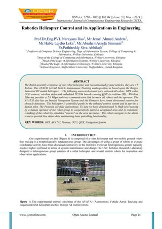
  • 1. ISSN (e): 2250 – 3005 || Vol, 04 || Issue, 5 || May – 2014 || International Journal of Computational Engineering Research (IJCER) www.ijceronline.com Open Access Journal Page 25 Robotics Helicopter Control and its Applications in Engineering Prof.Dr.Eng.PVL Narayana Rao1 , Mr.Jemal Ahmed Andeta2 , Mr.Habte Lejebo Leka3 , Mr.AbrahamAssefa Simmani4, Er.Pothireddy Siva Abhilash5 1 Professor of Computer Science Engineering, Dept. of Information System, College of Computing & Informatics, Wolkite University, Ethiopia 2 Dean of the College of Computing and Informatics, Wolkite University, Ethiopia 3 Head of the Dept. of Information Systems, Wolkite University, Ethiopia 4 Head of the Dept. of Information Technology, Wolkite University, Ethiopia 5 SoftwareEngineer, Staffordshire University, Staffordshire, United Kingdom I. INTRODUCTION Our experimental test bed (Figure 1) is composed of a robot helicopter and two mobile ground robots thus making it a morphologically heterogeneous group. The advantages of using a group of robots to execute coordinated activity have been discussed extensively in the literature. However heterogeneous groups typically involve higher overhead in terms of system maintenance and design.The USC Robotics Research Laboratory designed a heterogeneous group consists of a robot helicopter and several mobile robots for inspection and observation applications. Figure 1: The experimental testbed consisting of the AVATAI (Autonomous Vehicle Aerial Tracking and Inspection) robot helicopter and two Pioneer AT mobile robots. ABSTRACT The Robot assembly comprises of one robot helicopter and two unmanned ground vehicles, they are AT Robots. The AVATAI (Aerial Vehicle Autonomous Tracking andInspection) is based upon the Bergen Industrial RC model helicopter. The following sensors/electronics are onboard all robots; GPS, color CCD camera, wireless video and embedded PC/104 boards running QNX (a realtime OS). Wireless Ethernet provides a 2.0 Mbps multiway communication link between all robots and the operator. The AVATAI also has an Inertial Navigation System and the Pioneers have seven ultrasound sensors for obstacle detection. The helicopter is controlled partly by the onboard control system and in part by a human pilot. The Pioneers are fully autonomous. To date we have demonstrated 1) High-level tasking by a human operator of the robot group to cooperatively patrol a designated area and 2) Automatic retasking of the robots by simulated "alarms" on the area perimeter. The robots navigate to the alarm scene to provide live video while maintaining basic patrolling functionality. KEY WORDS: GPS, AVATAI, Pioneer, OCU, QNX, Navigation System
  • 2. Robotics Helicopter Control and its Applications in Engineering www.ijceronline.com Open Access Journal Page 26 In the work described here, we focus on an experimental task motivated by an application where a single person has control and tasks the robot group at a high level. A possible application is alarmed with security in urban areas where a single guard would need to control and monitor several (possibly heterogeneous) robots. In the application described here the robot group patrols an outdoor open area (a few obstacles are present on the ground) defined by a perimeter. The boundary is defined by a set of vertices (in GPS coordinates) which when connected by line segments form the boundary of a closed convex irregular polygon. In the work reported here the robot helicopter is flown by a human pilot for purposes of safety and speed. However we rely on a human pilot to transition from a stable hover at one point in space to another. Both ground robots are fully autonomous in the experiments reported here. The robots in the experiments cover the area bounded by the perimeter and send imagery back to a human operator via a wireless video downlink. The operator is able to set high level goals for the ground robots. An example of a high level goal is “follow the helicopter.” If a particular ground robot is given this high level goal it will stop patrolling and will follow the helicopter as it moves. The motivation behind this is to allow the ground robots to “take a closer look” at areas which the operator finds interesting based on aerial imagery. The operator can designate points of interest within the perimeter which serve as area markers for robots to periodically explore. The basic idea behind the implementation of the control programs is however to achieve robust functionality without explicit top-down planning. Rather the overall behavior of the group is the result of interacting control systems that run on the individual robots which essentially allow each robot a high degree of autonomy. II. HARDWARE AND SOFTWARE DESCRIPTION 2.1 AVATAI Hardware The current AVATAI, shown in Figure 1, is based upon the Bergen Industrial Helicopter, a radio controlled (RC) model helicopter. It has a two meter diameter main rotor, is powered by a 4.0 horsepower twin cylinder gas engine and has a payload capability of approximately 10 kilograms. The helicopter has five degrees of control: main rotor lateral and longitudinal cyclic pitch, tail rotorpitch, main rotor collective pitch and engine throttle. The first three control the roll, pitch and yaw of the helicopter while the last two control its thrust. The helicopter can be controlled by a humanpilot using a hand held transmitter which relays pilot control inputs to an onboard radio receiver using the 72 MHz frequency band. The receiver is connected to five actuators, one for each degree of control on the helicopter. For autonomous operation, these pilot control inputs are replaced by computer generated control inputs. A block diagram of the AVATAI system; including sensors, onboard and off board computing resources, wireless communication links and electrical power sources, is given in Figure 2. A variety of sensors are mounted on the AVATAI that provide information about the state of the helicopter as well as the environment in which it operates. An integrated Global Positioning System/Inertial Navigation System (GPS/INS) device, consisting of a GPS receiver and an Inertial Measurement Unit (IMU), is the primary sensor used for low-level control of the helicopter. The GPS/INS provides position (latitude, longitude and altitude), velocity (horizontal and vertical), attitude (roll and pitch), heading (yaw), delta theta and delta velocity information. This particular GPS receiver can only track 4 satellites at once and consequently provides a relatively poor estimate of current latitude and longitude as compared to other available receivers. So, a second standalone GPS receiver is used that can track up to 12 satellites at once. This improves the standard deviations of the estimates of latitude and longitude from 4.5 meters for the 4-channel GPS unit down to 20 centimeters for the 12-channel unit. This GPS receiver is used for the high-level (guidance and navigation) control of the helicopter. A downward facing ultrasonic (sonar) transducer provides altitude information and a RPM sensor mounted on the main rotor mast measures engine speed. A downward looking color CCD camera provides visual information of the area below the AVATAI.
  • 3. Robotics Helicopter Control and its Applications in Engineering www.ijceronline.com Open Access Journal Page 27 Figure 2: AVATAI system block diagram Onboard computing needs are met using a number of commercial off the shelf (COTS) PC/104 boards and one additional custom built PC/104 board. The main processor board contains a 486DX4 CPU which runs at 133 MHz, has 16 Mbytes of RAM and 40 Mbytes of solid state disk on chip (DOC). The DOC contains both the realtime operating system (RTOS) and flight software. The 486DX4 boots up the RTOS at system power up, executes all flight control and image processing software and provides an interface to other PC/104 boards. These boards include a timer/counter board used both to generate actuator commands and read pilot commands, a custom built PC/104 board that allows switching between human generated and robot generated commands on an actuator by actuator basis as well as acting as an interface to the RPM sensor and sonar, a serial port board for interfacing to the GPS/INS and standalone GPS, a color video frame grabber for the CCD camera and a PC/104 to PCMCIA interface board to allow the use of PCMCIA cards onboard the AVATAI. A 2.4 GHz wireless Ethernet PCMCIA card provides a multiway 2.0 Mbps communication link between the AVATAI, other robots and a human using an operator control unit (OCU). (The OCU comprises the off board computing resources and will be described in detail later). The human receives grabbed video frame information and other telemetry from the AVATAI and sends high-level tasking commands to the AVATAI via this link. In addition, differential GPS corrections are sent from the OCU to the GPS receivers onboard the AVATAI through the wireless Ethernet to improve the GPS performance. A live video feed, provided by a one way 1.3 GHz wireless video link from the CCD camera, is displayed on a monitor. Nickel-metal hydride (NiMH) and lithium-ion (Li- Ion) batteries supply power to the electronics. The GPS/INS is relatively power hungry, requiring 0.8 amps at +24 volts and so a dedicated 12-volt, 3.5 amp-hour NiMH battery is connected to a DC/DC converter to produce +24 volt power. The electronics can operate for roughly an hour with this battery supply. Mission length is limited by the flight time of the helicopter on a single tank of gasoline, which is approximately 30 minutes in duration. 2.2 AVATAI Software The operating system used is QNX; a UNIX-like, hard real time, multitasking, extensible POSIX RTOS with a small, robust microkernel ideal for embedded systems. The flight software encompasses all remaining software running onboard the AVATAI. This currently includes (or is planned to include): 1. low-level software drivers for interfacing with sensors and actuators 2. Flight control software for guidance, navigation, and control. 3. learning software 4. self-test software including built in test (BIT) and health checks software for increasing robot fault tolerance 5. vision processing software running on the frame grabber
  • 4. Robotics Helicopter Control and its Applications in Engineering www.ijceronline.com Open Access Journal Page 28 Figure 3: Pioneer system block diagram All software is written primarily in C/C++, with assembly used only when required for speed of execution. Custom drivers have been written for the timer/counter card, the GPS/INS and GPS units, the frame grabber and the wireless Ethernet PCMCIA card. The remaining software is still under development. 2.3 Pioneer Hardware The Pioneer AT robots used in this work is identical to each other. Each robot is four-wheeled base with skid steering. The wheels on the left are coupled mechanically as are the wheels on the right resulting in two degrees of freedom in the drive. Turning is accomplished by a speed differential between the left and right sides. Each robot has a Lithium-Ion (Li-Ion) battery pack (Two 10.8 volt, 4.05 amp-hour Li-Ion) for the electronics. The motors are powered by a lead acid battery that allows up to 4 hours of operation on hard surfaces and approximately one hour on grass. Each robot is equipped with a ring of seven front looking sonars which are controlled by a low-level Motorola 6811 microcontroller. The wheel speeds are available through encoders. The low-level 6811 board is connected to a PC/104 stack via a serial connection. The Pioneer also has a vision system comprised of a camera on a pan-tilt head controlled by a Motorola 68332 board running the Congnachrome color vision system. The main PC/104 processor board contains a 486DX4 133MHz CPU, 4 Mbytes of RAM and 40 Mbytes of solid state disk on chip which contains both the real time operating system (RTOS) and control software. Each robot is equipped with a NovaTel GPS system connected to the PC/104 processor via a serial port. Additional sensors include a compass and a gyroscope. The gyroscope is connected to a A/D card on the PC/104 stack. A 2.4 GHz wireless Ethernet PCMCIA card provides a multiway 2.0 Mbps communication link between each Pioneer and the other robots. A live video feed, provided by a one-way 2.3 GHz wireless video link from the CCD camera, is displayed on a monitor. A block diagram of the Pioneer hardware is given in Figure 3. 2.4 Pioneer Software The control system for the Pioneer AT (described in the next section) is all written in C and runs under QNX on the PC/104 stack described above. The software includes 1. Low-level software drivers for interfacing with sensors specifically software for the wireless Ethernet driver and the GPS driver. 2. control software for obstacle detection and avoidance, navigation and mapping 2.5 OCU Hardware The operator control unit is implemented using a Toshiba Tecra 510CDT laptop PC based upon a 133 MHz Pentium CPU. It has 144 Mbytes of RAM, a 4.3 Gbyte hard drive, a 12.1 inch high-res color monitor, a CD-ROM and an Ethernet connection. The QNX operating system is installed as well as the Watcom C/C++ compiler. A docking station expands the capabilities of the laptop by providing two full-length expansion slots for standard ISA and 32-bit PC Expansion Cards and onehalf-length 32-bit PC expansion slot. It also has a selectable bay for installing additional hardware such as CD-ROM drives or floppy drives. A 1.44M byte floppy drive has been installed in the slot.The 510CDT has multiple functions and is used during all phases of the project; including development, integration and test. The primary purpose of the laptop is to function as a wireless OCU for communication and tasking of the robots. A 2.4 GHz wireless Ethernet device is connected to the Toshiba, providing a multiway connection between the human at the OCU and the wireless PCMCIA cards
  • 5. Robotics Helicopter Control and its Applications in Engineering www.ijceronline.com Open Access Journal Page 29 onboard the robots. Additional functions of the 510CDT include the following: First, it provides a software development environment through the use of the QNX operating system and the Watcom C/C++ Compiler. Using this environment code is developed and tested. Also, using RCS, a QNX software version control utility, software configuration management is implemented. Second, the 4.3 Gbyte hard drivesprovide long-term storage capability for mission data. Third, the docking station provides an ISA slot for a GPS receiver used to produce differential GPS corrections for use by the mobile robots. III. USER INTERFACE The user interface for the system is implemented under QNX using the Phab GUI development system. The basic layout of the interface is deliberately kept simple so as to allow an inexperienced operator to quickly learn how to use it. A screenshot of the interface is shown in Figure 4. The user interface allows the operator to examine telemetry from any robot, task individual robots to do specific activities (such as following, patrolling etc.) and monitor the location of the robots in a 2D plan view. In addition, TV monitors show the operator a live wireless video feed from each of the individual robots. Tasking is done by selecting a robot with the mouse and clicking on one of the tasks available in the form of the task list popup menu. Figure 4: A screenshot of the user interface IV. RESULTS WITH TEST TASKS The system described here has been tested with two simple tasks to date. The operator initializes the system with a set of GPS coordinates that define the perimeter of interest. The robot locations are registered to a common coordinate frame which is displayed to the operator on the user interface. The first task used for testing was a cooperative patrolling activity by the robots. The helicopter was flown by the human pilot and the Pioneer ground vehicles followed it on the ground using GPS. The only input from the operator is at the start of the task. When the helicopter is fully autonomous we expect to be able to load a flight plan into it (in the form of several via points) and have the rest of the robots follow in loose formation. The second task we have used for testing involves the automatic retasking of the robots by simulated "alarms" on the area perimeter. The robots navigate to the alarm scene to provide live video while maintaining basic patrolling functionality. When an alarm goes off (alarms are simulated by user keyboard input to the system), the robot nearest to the alarm disengages the patrolling behavior and navigates to the site of the alarm. Since this is a reconnaissance style scenario the robot simply returns a close-up view of the scene of the alarm to the operator in the form of a live video feed. The other robot continues patrolling.A detailed analysis of the behavior of the group as a whole is the subject of a forthcoming paper [Sukhatme 99]. Videotapes of the system are available at http://robotics.usc.edu/brochure/afv.html.
  • 6. Robotics Helicopter Control and its Applications in Engineering www.ijceronline.com Open Access Journal Page 30 REFERENCES [1] Amidi, O. (1996), An Autonomous Vision-Guided Helicopter, PhD thesis, Department of Electrical and Computer Engineering, Carnegie Mellon University. [2] Arbib, M.A. (1995), Schema theory, in M.Arbib, ed., `The Handbook of Brain Theory and Neural Networks', MIT Press, Cambridge, MA, pp.830--834. [3] Arkin, R.C. (1990), `Integrating behavioral, perceptual, and world knowledge in reactive navigation', Robotics and Autonomous Systems 6,105--122. [4] Arkin, R.C. (1992), `Cooperation without communication: Multiagent schema based robot navigation', Journal of Robotic Systems. [5] Arkin, R.C. (1998), Behavior-Based Robotics, The MIT Press, Cambridge, MA. [6] Brooks, R.A. (1986), `A robust layered control system for a mobile robot', IEEE Journal Robotics and Automation 2(1),14--23. [6] Cavalcante, C., Cardoso, J., Ramos, J. J.G. & Neves, O.R. (1995), Design and tuning of a helicopter fuzzy controller, in `Proceedings of 1995 IEEE International Conference on Fuzzy Systems', Vol.3, pp.1549--1554. [7] DeBitetto, P., Johnson, E.N., Lanzilotta, E., Trott, C. & Bosse, M. (1996), The 1996 MIT/Boston University/Draper Laboratory autonomous helicopter system, in `Proceedings of 1996 Association for Unmanned Vehicle Systems 23rd Annual Technical Symposium and Exhibition', Orlando, pp.911--920. [8] Dedeoglu, G., Mataric, M. & Sukhatme, G.S. (1999), Cooperative robot mapping, in `Proceedings of the 1999 SPIE Conference'. [9] Fukuda, T., Nadagawa, S., Kawauchi, Y. & Buss, M. (1989), Structure decision for self-organizing robots based on cell structures - cebot, in `IEEE International Conference on Robotics and Automation', IEEE Computer Society Press, Los Alamitos, CA, Scottsdale, Arizona, pp.695--700. V. BIOGRAPHIES P.V.L. NARAYANA RAOwas born in Vijayawada, Krishna District, Andhra Pradesh, India. He completed M.Tech. from Sam Higginbottom Institute of Agriculture, Technology and Sciences Deemed University ( Formerly Allahabad Agricultural Institute),UP, India and PhD in Computer Science Engineering from Lingaya’s University, Faridabad, Haryana State, India. He has 8 years of National Teachingexperience in reputed India Post Graduation Engineering Colleges, 14 years of International Teaching experience in different Universities of Foreign Country Ethiopia, East Africa and 4 years National Industrial Experience in India as a System Analyst, Systems Developer. He iscurrently working as Professor (CSE), Wolkite University, SNNPR, P.O.Box No.7, Wolkite, Ethiopia, and East Africa. He is a member of various professionalsocieties likeWASET, USA, IAEng, Hongkog and CSE, Ethiopia. He has various publications in theNational and International Journals. JEMAL AHMEDANDETAwas born in Arekite, SNNPR, Ethiopia, and East Africa. He completed his graduation in Information Science from Haremaya University, Ethiopia, East Africa and presently working as the Dean of the college of Computing and Informatics in Wolkite University, Wolkite, Ethiopia. HABTE LEJEBOLEKA was born in Arba Minch, SNNPR, Ethiopia, and East Africa. He completed his graduation in Information System from Addis Ababa University, Ethiopia and now he is working as Head of the Department of Information System in Wolkite University, Wolkite, Ethiopia. ABRAHAM ASSEFA SIMMANI was born in Wolkite, SNNPR, Ethiopia, and East Africa. He completed his graduation in Information Technology from Wollega University, Ethiopia and now he is working as Head of the Department of Information Technology in Wolkite University, Wolkite, Ethiopia. POTHIREDDY SIVA ABHILASH was born in Vijayawada, Krishna District, Andhra Pradesh, India. He completed M.S degree in Tele Communication Engineering from Staffordshire University, Staffordshire, United Kingdom in 2013. He is working as Software Engineer in Hyderabad, Telangana State, India. He has various publications in the International Journals.