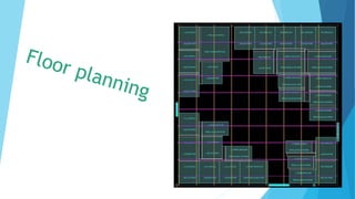
Floor planning
•Download as PPTX, PDF•
0 likes•405 views

it will explain about floorplaning steps in physical design

Recommended
More Related Content
What's hot
What's hot (20)
Similar to Floor planning
Similar to Floor planning (20)
Recently uploaded
Recently uploaded (20)
Floor planning
- 2. contents 1.Die Size estimation 2.core and IO creation 3.placing of macros and IO’s Placing of physical cells Power plan Blockage creation Floorplan creation and optimisation
- 3. 1.Die size estimation We can estimate our die size by using QOR(Quality Of Reports) and Utilisation Die Area in sq.mm = {[(Gate count + Additional gate count for CTS & ECO) / Gate density] + IO area + Mem, Macro area} / Target utilization
- 4. 2.Core and IO creation If you are doing a digital-top design, you need to place IO pads and IO buffers of the chip. Take a rectangular or square chip that has pads in four sides. To start with, you may get the sides and relative positions of the PADs from the designers. You will also get a maximum and minimum die size according to the package you have selected. To place IOs, I use a Perl script to place them once I decide on my chip size. IO”s
- 5. 3.Placing macros once you have the size & shape of the floorplan ready and initialized the floorplan, thereby creating standard cell rows, you are now ready to hand place your macros. Do not use any auto placement, I have not seen anything that works. Fly lines in your tool will show you the connection between the macros and standard cells or IOs. a. Use fly lines and make sure you place blocks that connects to each other closer b. For a full-chip, if hard macros connect to IOs, place them near the respective IOs c. Consider the power straps while placing macros. You can club macros/memories d. Creating Power Rings and Straps If you have more macros we will go with Data flow diagram, based on hierarchy(set _colors –cycle _color)
- 6. Floorplanning using flylines Floorplanning using color hierarchy
- 7. 4.Placing physical cells We have physical and logical cells Physical cells:- cells which does not have timing arcs Logical cells :- cells which have timing arc 1.ENDCAP 2. WELL TAPS 3.DECAP 4.FILLER 5.ANTENA DIODE 6.SPARE CELLS
- 8. 5.powerplan Power Planning is very important stage in Physical design during which we synthesize the power network in order to provide power to all macros and standard cells within the given IR-Drop limit, in our case 5% of (VDD+VSS). Steady state IR Drop is caused by the resistance of the metal wires comprising the power distribution network. By reducing the voltage difference between local power and ground, steady-state IR Drop reduces both the speed and noise immunity of the local cells and macros Stripes
- 9. 6.Blockage creation We have four types of Blockages 1.soft blockage 2.hard blockage 3.partial blockage 1.soft :-it will allow buf and inv only. 2.hard:- it does’nt allow any cells. 3.partial:- it will allow cells according to user defined percentage. blockage
- 10. Summary:- Aspect ratio: This is the ratio of height divided by width and determines whether you get a square or rectangular floorplan. An aspect ratio of 1 gives Core utilization = (standard cell area+ macro cells area)/ total core area. Aspect ratio= width/height OR horizontal resources / vertical routing resources . A core utilization of 0.8 means that 80% of the area is available for placement of cells, whereas 20% is left free for routing.you a square floorplan.