2. 2
Contents
1. INTRODUCTION
2. SYSTEM DESCRIPTION
3. SOFTWARE ARCHITECTURE
4. SIGNAL PROCESSING ALGORITHMS
4.1 ACQ Mode
4.2 POST Mode
4.3 FFT class
5. JOINT SIGNAL DETECTION AND ITERATIVE INTERFERENCE
CANCELLATION
5.1. Co-channel interference mitigation in RF test receivers
5.2. Reference pattern cross-correlation as dynamic range-limiting factor
5.3. Parallel iterative interference cancellation
5.4. Serial iterative interference cancellation
6. PERFORMANCE TEST: SYNTHESIZED PREAMBLES
6.1 Two preambles; level difference at 12 dB
6.2 Two preambles; level difference at 20 dB
7. FIELD PERFORMANCE TESTS
7.1. Car not moving, suburban location
7.2. Complete drive-test; Longear used to collect and process signals
8. CONCLUSION
3. 3
Introduction: RF Scanners
• Uses of scanners
• Traditional scanner, evolution, dead end
• Scanner market decline
• SON, indoor systems, het nets: new beginning
• Soft scanner: leveraging GP computing technology
• Longear project at Wavenetix: 3 years in
development. A multithreading HPC system for
signal collection and processing
4. 4
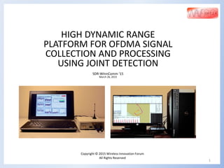
System description
• ACQ: signal acquisition mode
• POST: signal post processing mode
5 processing tasks/threads on laptop;
15 tasks on workstation
6. 6
Software architecture (2)
Signal engine
(C++)
Joint detector
(C++ / AVX)
FFT (C++
/ AVX)
Signal buffers Results
N x
Note: N is a configuration parameter stored in the database
7. 7
ACQ mode
Signal samples come
from the receiver via the
UHD driver. Each signal
“buffer” is a contiguous
interval that contains
several frames.
Segment into frame arrays
Measure power levels, run AGC, scale samples
Resample from 25 to 11.2 Msps
start
Save frame parameters in frame headers
Store frame segments and frame headers
Get signal buffer from UHD
Frame synchronization
8. 8
POST mode
Start Nth
thread
Write results into database
Get signal buffer and headers from file(s)
Pre/midamble synchronization
OFDM segment loop
Frame loop
Pre/midamble
loop
JD (opt)
Pre/midamble
scan
Basic OFDM correlation detector:
FFT#1
FFT#2
pre/midamble
symbols
peak detector
symbol
9. 9
FFT class
Advantages of implementing FFT as a class:
• An instance of FFT in a sig-proc thread gets its static memory independent
of other threads.
• Static arrays for storing signals make function calls more efficient; memory
use is not of concern.
• An example of beneficial use of static storage is storing a LUT for bit
reversal operation as a member of this class. It is generated during object
initialization.
FFT optimization steps:
• Started with the classic “Numerical Recipes” code (Lanczos-Daniels
algorithm).
• Unrolled first and last loop iterations.
• Tailored code to specific FFT size.
• Treated std::complex<float> arrays as pairs of interleaved real numbers by
using C pointers.
• The code uses Intel AVX intrinsics throughout. Each operation typically
involves eight floats. This lets the code do two butterflies in one iteration.
• Use of a look-up table for bit reversal step.
10. 10
ITERATIVE INTERFERENCE CANCELLATION(1)
Signal discernibility depends on the length of the code used for signal identification.
The processing gain: Gproc = 10 . log10(n);
SINR sufficient for reliable detection: 12 dB;
Discernibility (rule of thumb): 12 – Gproc.
Code lengths, processing gains, and discernibility of current and
older air protocols:
• GSM: ~150 symbols / 22 dB / 12 – 22 = -10 dB
• IS-95: 32K / 45 dB / 12 – 45 = -33 dB
• WCDMA ‘99: 38K / 46 dB / 12 – 46 = -34 dB
• 802.16e, 10 MHz: 284 / 24.5 dB / 12 – 24.5 = -12.5 dB
Example: two signals, S1/S2 = 12 dB, no IC :
5 dB
11. 11
ITERATIVE INTERFERENCE CANCELLATION(2)
“Parallel” and “Series” interference cancellation (definition):
• Parallel IC (“pic”) attempts to cancel all of the suspected interferers at
each step.
• Series IC (“sic”) cancels only the strongest interferer at each step,
minimizing probability of error.
PIC flow chart SIC: Joint preamble loop is replaced by the “analysis”
step, which finds the strongest response to cancel.
12. 12
ITERATIVE INTERFERENCE CANCELLATION(3)
Two preambles at 12 dB level difference that are processed using PIC:
16 dB
Simulated signals
NO IC PIC
Level delta, dB 12 12
Discernibility,
dB
5 16
13. 13
ITERATIVE INTERFERENCE CANCELLATION(4)
Two preambles at 20 dB level difference processed using PIC and SIC:
Simulated signals
NO IC PIC SIC
Level delta, dB 20 20 20
Discernibility, dB 0 9 30
NO IC PIC
9 dB
SIC
30 dB
14. 14
FIELD PERFORMANCE TESTS(1)
Stationary position, rural, PIC Lewis_Orchard_17_30 2667 MHz
Signal models Correlations with the
jointly detected
preambles at the input
to the last iteration
No joint detection After joint detection: P95 & P87
P95: 5.3 mi
P87: 8.7 mi
18. 18
FIELD PERFORMANCE TESTS(5)
Actual drive test, suburban
Level histograms: max and min detected level difference-per-frame
distribution (log scales both axes)
max/min, dB
10.log10(count+1)
19. Wavenetix is a private T&M company
Wavenetix offers technologies and services for wireless testing and is looking for
partnerships
Incorporated July 2010
Headquartered in Virginia
Products and services: systems and tools for the measurement and modeling of 4G
wireless wideband MIMO propagation channels, e.g. WCDMA, WiMAX, TD-SCDMA, LTE, LTE-
A, TD-LTE
Targeted markets:
Device and network test and test equipment providers
Wireless operators and network providers
19
CONCLUSION
Thank you!
Q & A