Design and Implement Any Digital Filters in Less than 60 Seconds
1. Link to ElecFilDes – The Electronic Filter Design Program referenced herein.
Design and Implement Any Digital Filter in Less than 60 Seconds
Digital filtering is one of the most powerful tools of DSP (digital signal
processing). Apart from the obvious advantages of virtually eliminating errors in
the filter associated with passive component fluctuations over time and
temperature, op amp drift (active filters), etc., digital filters are capable of
performance specifications that would, at best, be extremely difficult, if not
impossible, to achieve with an analog implementation.
Infinite impulse response (IIR) and Finite impulse response (FIR) filters
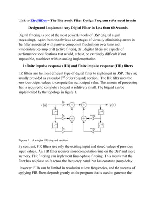
IIR filters are the most efficient type of digital filter to implement in DSP. They are
usually provided as cascaded 2nd
order (biquad) sections. The IIR filter uses the
previous output values to compute the next output value. The amount of processing
that is required to compute a biquad is relatively small. The biquad can be
implemented by the topology in figure 1.
Figure 1. A single IIR biquad section.
By contrast, FIR filters use only the existing input and stored values of previous
input values. An FIR filter requires more computation time on the DSP and more
memory. FIR filtering can implement linear-phase filtering. This means that the
filter has no phase shift across the frequency band, but has constant group delay.
However, FIRs can be limited in resolution at low frequencies, and the success of
applying FIR filters depends greatly on the program that is used to generate the
2. filter coefficients. Usage is generally more complicated and time-consuming than
IIR filters.
Figure 2. A FIR filter topology. Each z-1
block represents a delay of one sample
period.
On the MC56F84789VLL digital signal controller (DSC), a 512 tap filter would be
implemented by repeating the following instruction 512 times.
mac y0,x0,a x:(r0)+,y0 x:(r3)+,x0
Register 0 is a pointer to the input sample and delayed input samples. Register 3 is
a pointer to the b(n) coefficients used to multiply the input samples. The output is
the sum of all multiplications.
In the ElecFilDes filter design program, the coefficient resolution is 16 bits for FIR
designs, while 32 bit math is used to generate and process IIR coefficients.
ElecFilDes has a quantization routine that shows the degradation for using 16 bit
math in FIR designs, but the degradation is usually insignificant.
The ElecFilDes software will generate a coefficient file for any FIR and IIR design
within the programs capability. FIR designs are limited to Remez exchange
equiripple, or FIR window, designs with length of 512 taps, or less, and sampling
speeds between 1 to 100,000 samples per second. FIR window designs include
Hamming, Hanning, Rectangular, or Kaiser windows. The IIR designs can
accommodate all filter design options shown in figure 4 with sampling frequency
between 1 to 100,000 samples per second.
3. Figure 3. MC56F8400 evaluation board for the MC56F84789VLL DSC.
Figure 4. ElecFilDes Initial User Interface Screen. The example shown in figure 4
is for a 20th
order elliptic filter that blocks 2200Hz to 2800Hz and passes all other
4. frequencies. Simply clicking “Continue” generates the coefficient file which is
then ready to be assembled and downloaded by Codewarrior to the MC56F8400
demo board. The corresponding theoretical response, from ElecFilDes software, is
shown in figure 5.
Figure 5. Bandstop Response
It is interesting to note that removal of this 600Hz range in the audio spectrum is
not immediately apparent by listening to voice, or music.
An implementation block diagram is shown in figure 6.
Figure 6. Block diagram.
Optional Anti-
Aliasing Filter
MC56F84789VLL
based FIR/IIR
digital filter
engine on
MC56F8400
evaluation board
Optional
sin(x)/x DAC
correction filter
Audio
Amplifier
and Speaker
5. Anti-aliasing Filter:
Unless the user is advanced in using A/D sampling as a means of down conversion
and demodulation, it is advisable to use an analog anti-aliasing lowpass filter that
blocks all frequencies above ½ of the A/D sampling frequency. Frequencies above
½ the sampling rate will “fold over” into the lower frequency spectrum, causing
undesired interference. For a sampling rate of 100,000 Hz, the lowpass anti-
aliasing filter should have at least 40db of attenuation for frequencies above
50KHz. If the source does not contain frequencies above ½ the sampling
frequency, then an anti-aliasing filter is not necessary.
MC56F8400 Evaluation Board:
This board contains the MC56F84789VLL digital signal controller and has a 16-bit
A/D converter and a 12- bit DAC internal to the chip. The A/D converter can run at
100,000 samples per second or one sample every 10 microseconds. A typical
multiply and accumulate (MAC) instruction takes 10 nanoseconds using the DSC
at full speed, allowing for over 500 multiplication and additions within a 10
microsecond timeframe therefore making it possible to implement FIR filters of
up to 512 taps.
The signal at the input to the A/D converter must be up-biased to a 1.65 volt offset
since the A/D converter input range is 0 to 3.3 volts. The DAC output will also be
centered at a 1.65 volt offset, and should be AC coupled before audio
amplification.
Sin(x)/x Correction Filter:
The 12 bit digital-to-analog (DAC) is built into the MC56F84789VLL DSC chip.
All DACs have a frequency response and will attenuate the signal by 0.636 at ½
the sampling rate. For our previous example where the sampling rate was
100,000Hz, and the highest frequency of interest was much less than 50,000Hz, a
sin(x)/x correction filter is unnecessary because the DAC attenuation will be
insignificant.
6. ElecFilDes Design Program
This program can generate numerous filter designs that are capable of being
assembled within 60 seconds by Codewarrior, and downloaded to the MC56F400
EVB. ElecDesFil uses a proprietary scheme to associate transfer function zeroes
with corresponding poles for each quadratic section in order to minimize limit
cycle oscillations, overshoots, and problems commonly associated with other filter
implementations. However, because the DSC uses only 32 bit fixed point math in
the calculations for IIR filters, the response of some higher order elliptical IIR
filters will not be as sharp as theoretically possible. The program can design
elliptic filters, where the Q of the last stage is over 1,000,000. Implementation of
these filters results in a stable response, but because the Q is so high, and the
calculations use finite precision math, the passband edges will not be as sharp as
predicted. While it is tempting to always use a 20th
order elliptic filter, designs
should be restricted to a filter order that produces only the desired rolloff. High
order audio elliptic filters can also have a group delay extending into the 10’s of
seconds, which means that energy in the digital filter will decay very slowly after
the input signal is removed. The user will notice this as a faint tone that decays
over several seconds, if the filter order is too high.
ElecFilDes has a utility that lets the user determine the required filter order. The
example in figure 7 shows the filter orders necessary to pass 0-5000Hz, but
attenuate all frequencies above 5050Hz by 50dB.
The codewarrior view in figure 8 shows the two files that are required.
MASM.ASM is provided with the ElecDesFil software. During runtime,
MASM.ASM examines the coefficient file, DSPFILTER.ASM to determine if the
coefficients should be processed as an IIR, or FIR, filter. The highlighted “include”
line must be edited to provide the path to the DSPFILTER.ASM coefficient file.
To implement the filter, select PROJECT CLEAN, followed by RUN
DEBUG, followed by RUNRESUME. At this point, the design is running in the
DSC on the EVB.
8. Testing of FIR and IIR digital filters was done using a synthesized signal generator
and an oscilloscope to verify stability and timing for all designs. The demo setup,
used by the author, in figure 9, does not have an anti-aliasing filter, nor a DAC
sin(x)/x correction filter. The audio source is an FM radio, and the output of the
MC56F400 EVB is fed directly into an audio amplifier. A custom interface board
was used to interface to the EVB with the schematic shown in figure 10. The DSC
has an internal R-C oscillator and the frequency of this oscillator must be trimmed
by register control so that passband edges are accurate. A crystal oscillator option
is available, but uninstalled, if the EVB is purchased directly from Freescale.
Figure 9. Final Verification Station
9. For the circuit in figure 10, a custom modification on shorting pins 1 and 2 on J7
was made in able to provide 3.3 volts from the EVB to the interface board. The
EVB connects to a laptop through USB interface, for power and programming.
On the interface board, R2 and R3 are used to generate 1.65 volts to center the A/D
input. C1 forms a high pass filter to block any dc component from the input. C2 is
used to filter any power supply noise on the R2/R3 voltage divider that comes from
the 3.3 volts on the EVB. R1 injects the 1.65 volts onto the AC coupled input
signal without loading down the input source, and R4 provides current limiting
protection to the input of the A/D converter.
On the output side, R6 is used to eliminate hum during reset of the MC56F400
EVB when the DAC output goes into its high impedance state. R5 is to provide
current limiting protection to the DAC output.
While running, a small amount of 60Hz hum might be noticed. This can be
resolved by unplugging the power from the laptop running Codewarrior, so that the
laptop then becomes battery powered, thus eliminating the ground loop.
Figure 10. Custom Interface Board shown under the MC56F8400 EVB in figure 9.
R4 1K
A/D Input to Pin 38 of J501
C1
22uf
J4
Phono Connector
1
2
R3
1K
Audio
Output
DAC Output
C2
0.1uf
From Pin 21 of J502
J3
BNC
1
2
J1
BNC
1
2
R2
1K
R6
1K
R1
1K
R5 1K
J2
Phono Connector
1
2
From Pin 14 of J502
Audio
Input
From Pin 40 of J501
+3.3V