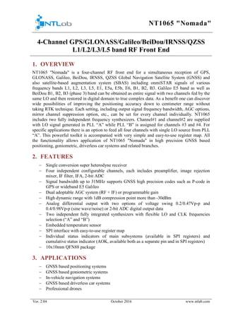
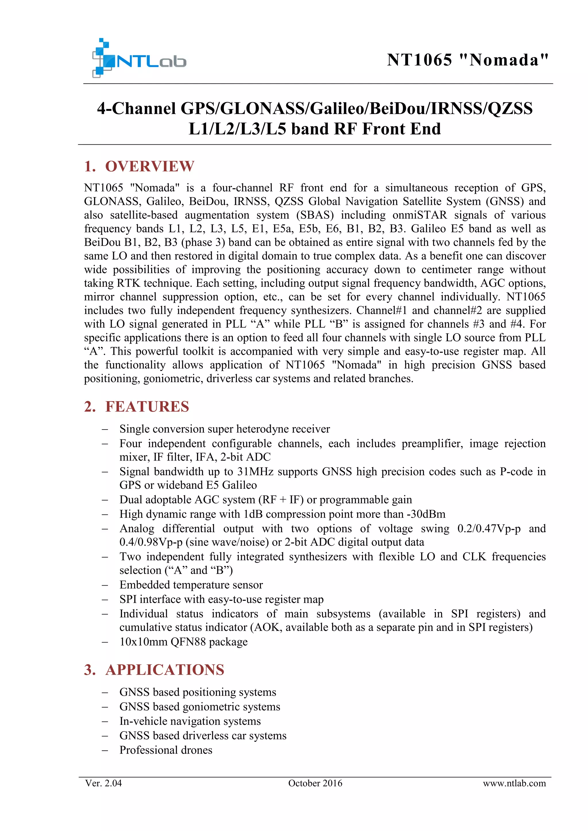
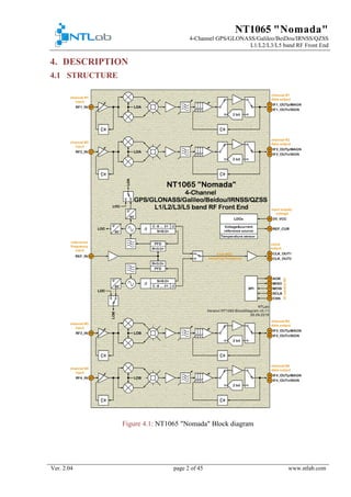
The document describes the NT1065 "Nomada", a 4-channel RF front end for simultaneously receiving signals from GPS, GLONASS, Galileo, BeiDou, IRNSS, and QZSS satellite systems. It has two independent frequency synthesizers that can each power two channels, and its functionality allows for high precision positioning applications. The device includes features such as independent configurable channels, high dynamic range, analog and digital outputs, and an SPI interface for configuration and status monitoring.
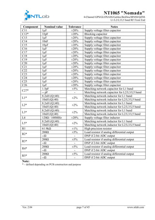
![NT1065 "Nomada"
4-Channel GPS/GLONASS/Galileo/BeiDou/IRNSS/QZSS
L1/L2/L3/L5 band RF Front End
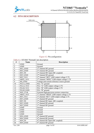
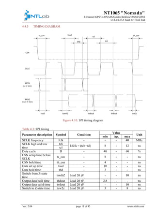
Ver. 2.04 page 30 of 45 www.ntlab.com
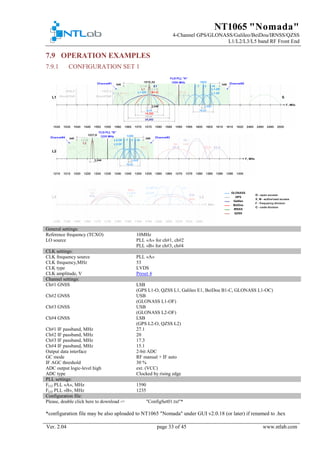
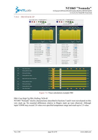
7. APPLICATION NOTES
Some tricks or not obvious actions as well as configuration examples are described in this
section
7.1 REFERENCE FREQUENCY (TCXO) CONFIGURATION AND
START UP PROCEDURE
After power up NT1065 "Nomada" assumes feeding with 10MHz TCXO signal and wakes up in
the active mode. PLLs are supposed to be locked after 1 ms and generally chip is ready for
operation. During next 15 ms LPF calibration procedure is running in background mode and has
no influence on channel filters. After completion a cut-off frequency correction code is applied
to all channels automatically and NT1065 "Nomada" has following configuration:
− PLL "A" is set to L1 band and feeds channel#1 and channel#2 with LO = 1590 MHz
− PLL "B" is set to L2/L3/L5 band and feeds channel#3 and channel#4 with LO = 1235
MHz
− Channel#1 down converts low side band (i.e. L1 GPS/Galileo/Beidou/QZSS)
− Channel#2 down converts high side band (i.e. L1 GLONASS)
− Channel#3 down converts high side band (i.e. L2 GLONASS)
− Channel#4 down converts low side band (i.e. L2 GPS/QZSS)
− All channels are set to analog differential output data interface, RF GC system in manual
mode @ max gain, IF GC system in auto mode
− PLL "A" and PLL "B" tuning systems were executed
− LPF auto-calibration system was executed
− 53 MHz CLK of LVDS type is pushed out
IF non 10MHz TCXO is used, some actions should be performed in order to make NT1065
"Nomada" perform properly. Execution sequence is important and described below.
24.84 MHz TCXO:
− set Reg3 D[1] to '1'
− perform PLL "A" and PLL "B" (if intended to use) reconfiguration according to section
7.2 to get desired LO frequency
− execute LPF auto-calibration system - Reg4 D[0]
Neither 10 MHz nor 24.84 MHz TCXO:
− contact NTLab in order to get initial configuration
− write this configuration to NT1065 registers
− execute PLL "A" and PLL "B" (if intended to use) auto tuning procedure - Reg43 D[0]
and Reg47 D[0] correspondingly
− execute LPF auto-calibration system - Reg4 D[0].
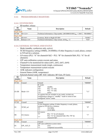
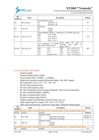
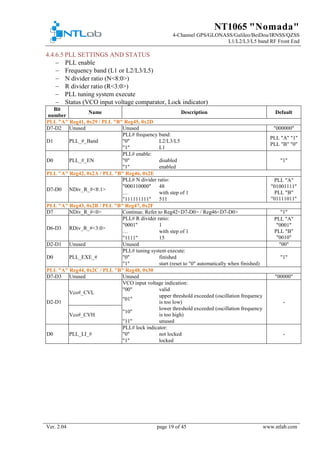
7.2 PLL "A"/ PLL "B" RECONFIGURATION
In order to reconfigure PLL following procedure is recommended:
− set Reg41/Reg45 D[1] to desired frequency band
− using the formula: 𝐹𝐹𝐿𝐿 𝐿𝐿 =
N∗𝐹𝐹𝑇𝑇𝑇𝑇𝑇𝑇𝑇𝑇
𝑅𝑅
choose N and R
− write N value to Reg42/Reg46 D[7-0] + Reg43/Reg47 D[7]
− write R value to Reg43/Reg47 D[6-3]
− execute tuning procedure - Reg43/Reg47 D[0]](https://image.slidesharecdn.com/204db091-d546-459a-812e-0b7958a54da0-161028110927/85/NT1065-LE-DS-v2-04-30-320.jpg)
![NT1065 "Nomada"
4-Channel GPS/GLONASS/Galileo/BeiDou/IRNSS/QZSS
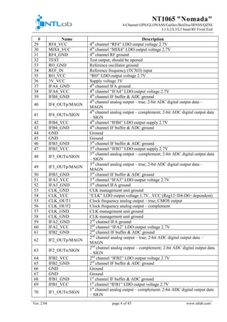
L1/L2/L3/L5 band RF Front End
Ver. 2.04 page 31 of 45 www.ntlab.com
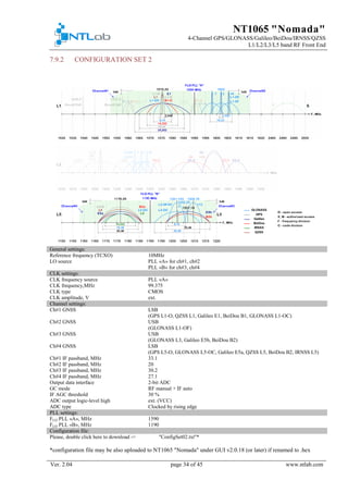
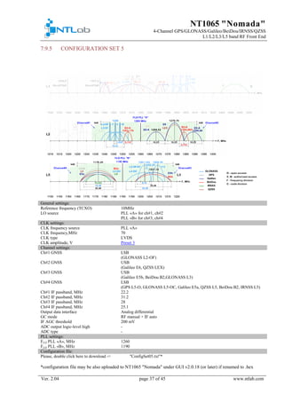
7.3 SINGLE LO SOURCE CONFIGURATION
In order to switch to single LO mode following actions are to perform:
− set Reg3 D[0] to '0' to feed all mixers from PLL "A"
− turn off PLL "B" by setting Reg45 D[0] to '0'
− reconfigure PLL "A" according to desired frequency plan using Reg41-44 if needed
(refer to section 7.2 for guidance).
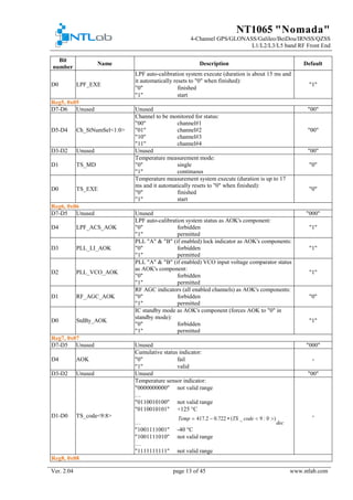
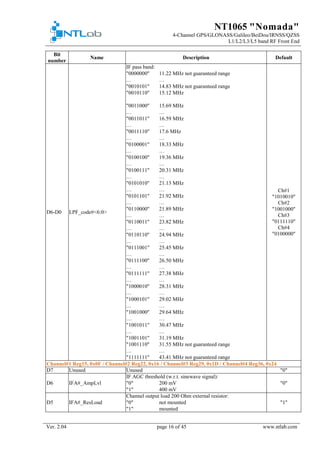
7.4 RF AGC CONFIGURATION
RF GC system of NT1065 "Nomada" starts in the manual operation mode. You can change RF
gain value manually by setting corresponding value with Reg17 D[7-4] for Channel#1 / Reg24
D[7-4] for Channel#2 / Reg31 D[7-4] for Channel#3 / Reg38 D[7-4] for Channel#4.
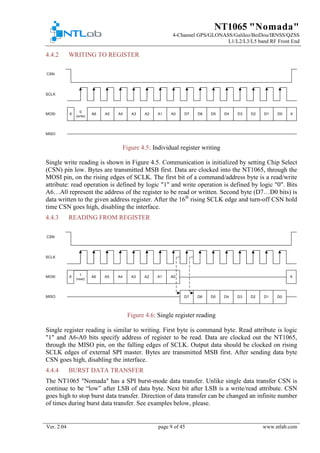
Actual RF power detector status is available at Reg9 D[5-4] in both manual and automatic
modes. Reg9 D[5] indicates the crossing of upper threshold and Reg9 D[4] indicates the crossing
of lower one. The thresholds are corresponding to the definite level of output power of input
stage that’s why they depend on RF Gain value. The thresholds’ values in Reg description table
are shown for max RF Gain settings (Reg17 D[7-4] for Channel#1 / Reg24 D[7-4] for Channel#2
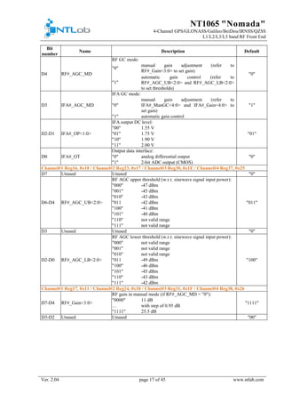
/ Reg31 D[7-4] for Channel#3 / Reg38 D[7-4] = "1111" for Channel#4). To calculate the actual
dBm-value of the threshold please use the equation:
𝑇𝑇𝑇𝑇𝐴𝐴 𝐴𝐴𝐴𝐴 = 𝑇𝑇𝑇𝑇𝐺𝐺𝐺𝐺𝐺𝐺𝐺𝐺𝐺𝐺 + 25.5𝑑𝑑𝑑𝑑 − 𝐺𝐺𝐺𝐺𝑆𝑆𝑆𝑆𝑆𝑆,
where
𝑇𝑇𝑇𝑇𝐴𝐴𝐴𝐴𝐴𝐴 - actual threshold value, dBm;
𝑇𝑇𝑇𝑇𝐺𝐺𝐺𝐺𝐺𝐺𝐺𝐺𝐺𝐺 - threshold value for max RF Gain (shown in reg description table), dBm;
𝐺𝐺𝐺𝐺𝑆𝑆 𝑆𝑆𝑆𝑆 - actual RF Gain, chosen by settings, dB.
Figure 7.1: RF AGC power detector status operation logic
An upper threshold could be adjusted by Reg16 D[6-4] for Channel#1 / Reg23 D[6-4] for
Channel#2 / Reg30 D[6-4] for Channel#3 / Reg37 D[6-4] for Channel#4. A lower threshold
could be adjusted by Reg16 D[2-0] for Channel#1 / Reg23 D[2-0] for Channel#2 / Reg30 D[2-0]
for Channel#3 / Reg37 D[2-0] for Channel#4. Power values shown in registers description table
are calculated with respect to input signal power. The upper threshold should always be higher
than lower. Also it is strongly recommended to set dBm-value of upper threshold at least 3dB
higher than lower threshold to guarantee stability of RF AGC loop.
The RF AGC thresholds can be changed in order to improve RF channel linearity by decreasing
dBm value of both thresholds (IM3 will increase since each block will operate with weaker input
signal) or to improve RF channel noise figure by increasing thresholds' dBm value (noise of
channel blocks will be more suppressed by higher gain of input amplifier and SNR of the
receiver will be improved).
To enable automatic mode the Reg15 D[4] for Channel#1 / Reg22 D[4] for Channel#2 / Reg29
D[4] for Channel#3 / Reg36 D[4] for Channel#4 should be switched to "1". While automatic](https://image.slidesharecdn.com/204db091-d546-459a-812e-0b7958a54da0-161028110927/85/NT1065-LE-DS-v2-04-31-320.jpg)
![NT1065 "Nomada"
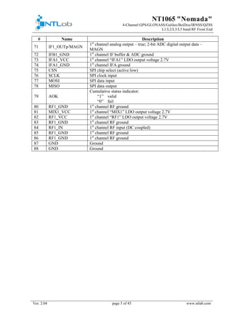
4-Channel GPS/GLONASS/Galileo/BeiDou/IRNSS/QZSS
L1/L2/L3/L5 band RF Front End
Ver. 2.04 page 32 of 45 www.ntlab.com
mode enabled, the RF AGC system will adjust the RF gain to keep its output power between RF
AGC thresholds.
The status of RF gain control register is available at Reg9 D[3-0].
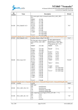
7.5 IF AGC THRESHOLD CONFIGURATION
If 400mV (w.r.t. sine wave signal) option is chosen for output peak-to peak voltage (Reg15 D[6]
for Channel#1 / Reg22 D[6] for Channel#2 / Reg29 D[6] for Channel#3 / Reg36 D[6] for
Channel#4) it is recommended not to solder terminating 200 Ohm resistor and to write
appropriate values ("0") to D[5] of the same registers. It will result in better linearity
performance.
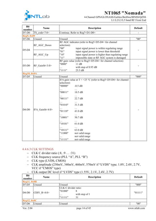
7.6 CLK FREQUENCY CONFIGURATION
CLK signal is intended for clocking all 2-bit ADCs as well as clocking external correlator
engine. It is generated from LO frequency either from PLL "A" or PLL "B" according to the
formula: 𝐹𝐹𝐶𝐶𝐶𝐶 𝐶𝐶 =
𝐹𝐹𝐿𝐿𝐿𝐿
2∗𝐶𝐶
. CLK source and frequency can be customized by procedure:
− choose CLK source by setting appropriate value to Reg12 D[5]
− write C value to Reg11 D[4-0]
7.7 CLK OUTPUT TYPE USAGE
Although CMOS output is available for usage it is recommended to select LVDS CLK output. It
is related to appearing of interferences at the LNA#_IN pins and then down converting to IF
band. These interferences are caused by CLK signal harmonics and allocated frequencies can be
calculated as 𝐹𝐹𝑗𝑗 𝑗𝑗𝑗𝑗 = 𝑁𝑁 ∗ 𝐹𝐹𝐶𝐶𝐶𝐶 𝐶𝐶, 𝑁𝑁 = 1,2,3,4 …
7.8 TEMPERATURE MEASUREMENT PROCEDURE
Two modes of temperature modes are available: single and continuous (Reg5 D[1]). In single
mode the measurement is done once upon request to Reg5 D[0] by setting '1' and result will be
stored in Reg7 D[1-0] + Reg8 D[7-0] after procedure is finished (auto reset to '0' in Reg5 D[0]
indicates this) until next execution. One temperature measurement procedure time is up to 17 ms.
To enter in continuous mode set Reg5 D[1] to '1' first then execute with Reg5 D[0]. In this case
embedded temperature sensor periodically runs the measurement procedure and only the latest
result is stored in Reg7 D[1-0] + Reg8 D[7-0]. In order to stop continuous execution Reg5 D[1]
should be set to '0'.](https://image.slidesharecdn.com/204db091-d546-459a-812e-0b7958a54da0-161028110927/85/NT1065-LE-DS-v2-04-32-320.jpg)