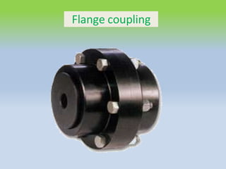
SlideShare a Scribd company logo
1 of 24
Flange coupling
Flange coupling
• A flange coupling usually applies to a coupling having
two separate cast iron flanges.
• Each flange is mounted on the shaft end and keyed to
it.
• The faces are turned up at right angle to the axis of the shaft
• Flange coupling are
• 1. Unprotected type flange coupling
• 2. Protected type flange coupling
• 3. Marine type flange coupling
1.Unprotected type flange coupling
• In an unprotected type flange coupling each
shaft is keyed to the boss of a flange with a
counter sunk key and the flanges are coupled
together by means of bolts.
• Generally, three, four or six bolts are used
Design of Unprotected type Flange Coupling
• The usual proportions for an unprotected type cast iron flange
couplings
• d = diameter of the shaft or inner diameter of the hub
• D= Outside diameter of hub D=2d
• Length of hub, L= 1.5d
• Pitch circle diameter of bolts, D1=3d
• Outside diameter of flange,
D2= D1+ ( D1– D) = 2 D1– D= 4d
• Thickness of flange tf =0.5d
• Number of bolts =3, ford upto 40 mm
=4, for d upto 100 mm
=6, for d upto 180 mm
• d =Diameter of shaft or inner diameter of hub,
• τs =Allowable shear stress forshaft,
• D=Outer diameter of hub,
• tf =Thickness of flange
• τc=Allowable shear stress for the flange material
• d 1=Nominal or outside diameter of bolt,
• D1 =Diameter of bolt circle,
• n=Number of bolts,
• τb= Allowable shear stress forbolt
• σ cb,, =Allowable crushing stress forbolt
• τk= Allowable shear stress for key material
• σ ck= keymaterial
1. Design for hub
• The hub is designed by considering it as a
hollow shaft,
• transmitting the same torque (T ) as that of a solid
shaft
T= T = (π/16)×τc×(D4-d4)/D
The outer diameter of hub is usually taken as twice
the diameter of shaft.
• The length of hub ( L ) = 1.5d
2. Design for key
The material of key is usually the same as that of
shaft. The length of key is taken equal to the
length of hub
l=L
• T = l× w×τ ×(d /2)
(Considering shearing of the key)
• T = l × t/2 × σC × (d/2)
(Considering crushing of the key
3. Design for flange
• T =Circumference of hub × Thickness of flange
× Shear stress of flange × Radius of hub
• T= π D × tf × τc × D/2
T= π × tf × τc × D2/2
The thickness of flange is usually taken as half the
diameter of shaft
4. Design for bolts
• Load on each bolt (F)=(π/4) (d 1)(τb)
• Total load on all the bolts (F) =(π/4) (d 1)(τb)(n)
• The bolts are subjected to shear stress due to the
torque transmitted (T)= (π/4) (d 1) (τb)(n)(D1/2)
From this equation, the diameter of bolt (d 1 )
may be obtained.
• We know that area resisting crushing of all the
bolts = n× d 1 × tf
• crushing strength of all the bolts
= n× d 1 × tf × σCb
Torque = n× d 1 × tf × σCb × (D1/2)
• From this equation, the induced crushing
stress in the bolts may be checked
Protected type flange coupling
• the protruding bolts and nuts are protected by
flanges on the two halves of the coupling, in
order to avoid danger to the workman
(tp ) =0.25d
The design of unprotective type is same
process of protective type
Marine type flange coupling
• In a marine type flange coupling, the flanges are forged
integral with the shafts .
• The flanges are held together by means of tapered
head less bolts.
• numbering from four to twelve depending upon the
diameter of shaft.
• Shaft diameter
• 35 to 55
• 56 to 150
• 151 to 230
• 231 to 390
• Above 390
No. of bolts
4
6
8
10
12
• The other proportions for the marine type
flange coupling
• Thickness of flange =d / 3
• Taper of bolt= 1 in 20 to 1 in 40
• Pitch circle diameter of bolts, D1= 1.6d
• Outside diameter of flange, D2= 2.2d
Bushed-pin Flexible Coupling
a modification of the rigid type of flange
coupling.
• The coupling bolts are known as pins. The
rubber or leather bushes are used over the
pins.
• The two halves of the coupling are dissimilar
in construction.
• A clearance of 5 mm is left between the face
of the two halves of the coupling.
• the proportions of the rigid type flange
coupling
• the bearing pressure on the rubber or leather
bushes and it should not exceed 0.5 N/mm2
Pin and bush design
• l=Length of bush in the flange,
• d 2=Diameter of bush,
• pb=Bearing pressure on the bush or pin,
• n=Number of pins,
• D1=Diameter of pitch circle of the pins
Pin and bush design
• bearing load acting on each pin,
• W = pb×d 2×l
• ∴Total bearing load on the bush or pins
• W × n= pb×d 2×l ×n
• torque transmitted by the coupling=
T= W × n × (D1 /2)
T= pb×d 2×l ×n × (D1 /2)
• Direct shear stress due to pure torsion in the
coupling halve
• τ=W/[ (π/4) (d 1 )]
2
• maximum bending moment on the pin
• M =W (l/2 +5mm)
• bending stress
σ= M / Z
= W (l/2 +5mm)/ (π/32) (d 1
3)
• Maximum principal stress
= 1/2[σ +(σ+4τ2 )1/2]
• maximum shear stress on the pin
= 1/2(σ+4τ2 )1/2
• The value of maximum principal stress varies
from 28 to 42 MPa

More Related Content

What's hot

Shaft. keys and cuopling
Shaft. keys and cuoplingShaft. keys and cuopling
Shaft. keys and cuoplingSvabhiman Singh
 
Design of Helical Gear box
Design of Helical Gear boxDesign of Helical Gear box
Design of Helical Gear boxAMIR92671
 
Gear and Gear trains
Gear and Gear trainsGear and Gear trains
Gear and Gear trainsMANJUNATH N
 
Rolling contact bearings
Rolling contact bearingsRolling contact bearings
Rolling contact bearingsChetan Rajula
 
Types of coupling
Types of couplingTypes of coupling
Types of couplingPrEet SheTh
 
Internal expanding shoe brake short presentation
Internal expanding shoe brake short presentationInternal expanding shoe brake short presentation
Internal expanding shoe brake short presentationJayanshu Gundaniya
 
Design of keys
Design of keysDesign of keys
Design of keysnsvnhanu
 
Design of helical spring against static loading
Design of helical spring against static loadingDesign of helical spring against static loading
Design of helical spring against static loadingakashpatel281996
 
Bushed pin type flexible coupling
Bushed pin type flexible couplingBushed pin type flexible coupling
Bushed pin type flexible couplingnarendra varma
 
Bushed pin type flexible coupling
Bushed pin type flexible couplingBushed pin type flexible coupling
Bushed pin type flexible couplinglj7252
 
Performance testing of IC engine
Performance testing of IC enginePerformance testing of IC engine
Performance testing of IC engineINDRAKUMAR PADWANI
 
torque , power, volumetric efficiency and their dependence on unit air charge...
torque , power, volumetric efficiency and their dependence on unit air charge...torque , power, volumetric efficiency and their dependence on unit air charge...
torque , power, volumetric efficiency and their dependence on unit air charge...mp poonia
 
10 gear manufacturing process
10  gear manufacturing process10  gear manufacturing process
10 gear manufacturing processM Siva Kumar
 

What's hot (20)

Design of Helical Spring
Design of Helical SpringDesign of Helical Spring
Design of Helical Spring
 
Shaft. keys and cuopling
Shaft. keys and cuoplingShaft. keys and cuopling
Shaft. keys and cuopling
 
U3 design of connecting rod
U3 design of connecting rodU3 design of connecting rod
U3 design of connecting rod
 
Design of Helical Gear box
Design of Helical Gear boxDesign of Helical Gear box
Design of Helical Gear box
 
Gear trains
Gear trainsGear trains
Gear trains
 
Gear and Gear trains
Gear and Gear trainsGear and Gear trains
Gear and Gear trains
 
Rolling contact bearings
Rolling contact bearingsRolling contact bearings
Rolling contact bearings
 
Types of coupling
Types of couplingTypes of coupling
Types of coupling
 
Unit 3.2 Design of Clutches
Unit 3.2 Design of ClutchesUnit 3.2 Design of Clutches
Unit 3.2 Design of Clutches
 
Internal expanding shoe brake short presentation
Internal expanding shoe brake short presentationInternal expanding shoe brake short presentation
Internal expanding shoe brake short presentation
 
Design of keys
Design of keysDesign of keys
Design of keys
 
Design of helical spring against static loading
Design of helical spring against static loadingDesign of helical spring against static loading
Design of helical spring against static loading
 
Bushed pin type flexible coupling
Bushed pin type flexible couplingBushed pin type flexible coupling
Bushed pin type flexible coupling
 
Bushed pin type flexible coupling
Bushed pin type flexible couplingBushed pin type flexible coupling
Bushed pin type flexible coupling
 
Performance testing of IC engine
Performance testing of IC enginePerformance testing of IC engine
Performance testing of IC engine
 
Unit 2.3 Design of Coupling
Unit 2.3 Design of CouplingUnit 2.3 Design of Coupling
Unit 2.3 Design of Coupling
 
sliding and rolling contact bearings
sliding and rolling contact bearingssliding and rolling contact bearings
sliding and rolling contact bearings
 
torque , power, volumetric efficiency and their dependence on unit air charge...
torque , power, volumetric efficiency and their dependence on unit air charge...torque , power, volumetric efficiency and their dependence on unit air charge...
torque , power, volumetric efficiency and their dependence on unit air charge...
 
10 gear manufacturing process
10  gear manufacturing process10  gear manufacturing process
10 gear manufacturing process
 
Design and Drawing of CAM profiles
Design and Drawing of CAM profilesDesign and Drawing of CAM profiles
Design and Drawing of CAM profiles
 

Similar to Flange Coupling Design Guide

Design of shafts couplings ppt
Design of shafts couplings  pptDesign of shafts couplings  ppt
Design of shafts couplings pptnsvnhanu
 
10 b couplings sleeve or muff-coupling
10 b couplings   sleeve or muff-coupling10 b couplings   sleeve or muff-coupling
10 b couplings sleeve or muff-couplingDr.R. SELVAM
 
Machine Design and Industrial Drafting.pptx
Machine Design and Industrial Drafting.pptxMachine Design and Industrial Drafting.pptx
Machine Design and Industrial Drafting.pptxNilesh839639
 
Connections
ConnectionsConnections
Connectionssky hawk
 
ch-02_cotter-joint-knuckle-joint-design.pdf
ch-02_cotter-joint-knuckle-joint-design.pdfch-02_cotter-joint-knuckle-joint-design.pdf
ch-02_cotter-joint-knuckle-joint-design.pdfPraveen Kumar
 
Design of shaft couplings
Design of shaft couplingsDesign of shaft couplings
Design of shaft couplingsmishini anil
 
Design of cotter joint (machine design & industrial drafting )
Design of cotter joint (machine design & industrial drafting )Design of cotter joint (machine design & industrial drafting )
Design of cotter joint (machine design & industrial drafting )Digvijaysinh Gohil
 
DESIGN OF RIVETED JOINTS.pptx
DESIGN OF RIVETED JOINTS.pptxDESIGN OF RIVETED JOINTS.pptx
DESIGN OF RIVETED JOINTS.pptxPraveenK19954
 
Internal combustion engine components design
Internal combustion engine components designInternal combustion engine components design
Internal combustion engine components designKailash Bhosale
 
Design of knuckle joint (machine design & industrial drafting )
Design of knuckle joint (machine design & industrial drafting )Design of knuckle joint (machine design & industrial drafting )
Design of knuckle joint (machine design & industrial drafting )Digvijaysinh Gohil
 
Cotter and Knuckle Joints.ppt
Cotter and Knuckle Joints.pptCotter and Knuckle Joints.ppt
Cotter and Knuckle Joints.pptpsshinde1
 
Design of Machine Elements- Unit 2 Procedures
Design of Machine Elements- Unit 2 ProceduresDesign of Machine Elements- Unit 2 Procedures
Design of Machine Elements- Unit 2 Proceduress Kumaravel
 
Connections in steel structures
Connections in steel structuresConnections in steel structures
Connections in steel structuresanand bhatnagar
 
Couplings by wishall
Couplings by wishallCouplings by wishall
Couplings by wishallvishal patil
 
Couplings by wishall patil
Couplings by wishall patilCouplings by wishall patil
Couplings by wishall patilvishal patil
 

Similar to Flange Coupling Design Guide (20)

Design of shafts couplings ppt
Design of shafts couplings  pptDesign of shafts couplings  ppt
Design of shafts couplings ppt
 
design of couplings.pptx
design of couplings.pptxdesign of couplings.pptx
design of couplings.pptx
 
10 b couplings sleeve or muff-coupling
10 b couplings   sleeve or muff-coupling10 b couplings   sleeve or muff-coupling
10 b couplings sleeve or muff-coupling
 
Machine Design and Industrial Drafting.pptx
Machine Design and Industrial Drafting.pptxMachine Design and Industrial Drafting.pptx
Machine Design and Industrial Drafting.pptx
 
Connections
ConnectionsConnections
Connections
 
ch-02_cotter-joint-knuckle-joint-design.pdf
ch-02_cotter-joint-knuckle-joint-design.pdfch-02_cotter-joint-knuckle-joint-design.pdf
ch-02_cotter-joint-knuckle-joint-design.pdf
 
Shaft
ShaftShaft
Shaft
 
Design of shaft couplings
Design of shaft couplingsDesign of shaft couplings
Design of shaft couplings
 
Cotter joint
Cotter jointCotter joint
Cotter joint
 
Design of cotter joint (machine design & industrial drafting )
Design of cotter joint (machine design & industrial drafting )Design of cotter joint (machine design & industrial drafting )
Design of cotter joint (machine design & industrial drafting )
 
DESIGN OF RIVETED JOINTS.pptx
DESIGN OF RIVETED JOINTS.pptxDESIGN OF RIVETED JOINTS.pptx
DESIGN OF RIVETED JOINTS.pptx
 
Fmd riveted joints
Fmd riveted jointsFmd riveted joints
Fmd riveted joints
 
Levers.pdf
Levers.pdfLevers.pdf
Levers.pdf
 
Internal combustion engine components design
Internal combustion engine components designInternal combustion engine components design
Internal combustion engine components design
 
Design of knuckle joint (machine design & industrial drafting )
Design of knuckle joint (machine design & industrial drafting )Design of knuckle joint (machine design & industrial drafting )
Design of knuckle joint (machine design & industrial drafting )
 
Cotter and Knuckle Joints.ppt
Cotter and Knuckle Joints.pptCotter and Knuckle Joints.ppt
Cotter and Knuckle Joints.ppt
 
Design of Machine Elements- Unit 2 Procedures
Design of Machine Elements- Unit 2 ProceduresDesign of Machine Elements- Unit 2 Procedures
Design of Machine Elements- Unit 2 Procedures
 
Connections in steel structures
Connections in steel structuresConnections in steel structures
Connections in steel structures
 
Couplings by wishall
Couplings by wishallCouplings by wishall
Couplings by wishall
 
Couplings by wishall patil
Couplings by wishall patilCouplings by wishall patil
Couplings by wishall patil
 

More from Dr.R. SELVAM

7 breakeven analysis
7 breakeven analysis7 breakeven analysis
7 breakeven analysisDr.R. SELVAM
 
6 fixed assets, current assets, depreciation methods
6 fixed assets, current assets, depreciation methods6 fixed assets, current assets, depreciation methods
6 fixed assets, current assets, depreciation methodsDr.R. SELVAM
 
5 preparation and interpretation of balance sheets
5 preparation and interpretation of balance sheets5 preparation and interpretation of balance sheets
5 preparation and interpretation of balance sheetsDr.R. SELVAM
 
4 acounting principle
4 acounting principle4 acounting principle
4 acounting principleDr.R. SELVAM
 
3 capital structure
3 capital structure3 capital structure
3 capital structureDr.R. SELVAM
 
1 sources of finance
1 sources of finance1 sources of finance
1 sources of financeDr.R. SELVAM
 
4 b. capital budgeting and cost analysis performance evaluation
4 b. capital budgeting and cost analysis   performance evaluation4 b. capital budgeting and cost analysis   performance evaluation
4 b. capital budgeting and cost analysis performance evaluationDr.R. SELVAM
 
4 a. capital budgeting and cost analysis
4 a. capital budgeting and cost analysis4 a. capital budgeting and cost analysis
4 a. capital budgeting and cost analysisDr.R. SELVAM
 
3 capital budgeting
3 capital budgeting3 capital budgeting
3 capital budgetingDr.R. SELVAM
 
1 current assement management
1 current assement management1 current assement management
1 current assement managementDr.R. SELVAM
 
2 b. project termination
2 b. project termination2 b. project termination
2 b. project terminationDr.R. SELVAM
 
2 a. project auditing
2 a. project auditing2 a. project auditing
2 a. project auditingDr.R. SELVAM
 
1 b, evaluation of project
1 b, evaluation of project1 b, evaluation of project
1 b, evaluation of projectDr.R. SELVAM
 
1 a, monitoring and evaluation of PM
1 a, monitoring and evaluation of PM1 a, monitoring and evaluation of PM
1 a, monitoring and evaluation of PMDr.R. SELVAM
 
3 industrial hydraulic circuits shapping, milling, drilling
3 industrial hydraulic circuits   shapping, milling, drilling3 industrial hydraulic circuits   shapping, milling, drilling
3 industrial hydraulic circuits shapping, milling, drillingDr.R. SELVAM
 
2 maintenance of hydraulic systems
2 maintenance of hydraulic systems2 maintenance of hydraulic systems
2 maintenance of hydraulic systemsDr.R. SELVAM
 
1 hydraulic troubleshooting
1 hydraulic troubleshooting1 hydraulic troubleshooting
1 hydraulic troubleshootingDr.R. SELVAM
 
3 c. industrial pneumatic circuit logic
3 c. industrial pneumatic circuit   logic3 c. industrial pneumatic circuit   logic
3 c. industrial pneumatic circuit logicDr.R. SELVAM
 

More from Dr.R. SELVAM (20)

7 breakeven analysis
7 breakeven analysis7 breakeven analysis
7 breakeven analysis
 
6 fixed assets, current assets, depreciation methods
6 fixed assets, current assets, depreciation methods6 fixed assets, current assets, depreciation methods
6 fixed assets, current assets, depreciation methods
 
5 preparation and interpretation of balance sheets
5 preparation and interpretation of balance sheets5 preparation and interpretation of balance sheets
5 preparation and interpretation of balance sheets
 
4 acounting principle
4 acounting principle4 acounting principle
4 acounting principle
 
3 capital structure
3 capital structure3 capital structure
3 capital structure
 
1 sources of finance
1 sources of finance1 sources of finance
1 sources of finance
 
2 term loan
2 term loan2 term loan
2 term loan
 
4 b. capital budgeting and cost analysis performance evaluation
4 b. capital budgeting and cost analysis   performance evaluation4 b. capital budgeting and cost analysis   performance evaluation
4 b. capital budgeting and cost analysis performance evaluation
 
4 a. capital budgeting and cost analysis
4 a. capital budgeting and cost analysis4 a. capital budgeting and cost analysis
4 a. capital budgeting and cost analysis
 
3 capital budgeting
3 capital budgeting3 capital budgeting
3 capital budgeting
 
2 working capital
2 working capital2 working capital
2 working capital
 
1 current assement management
1 current assement management1 current assement management
1 current assement management
 
2 b. project termination
2 b. project termination2 b. project termination
2 b. project termination
 
2 a. project auditing
2 a. project auditing2 a. project auditing
2 a. project auditing
 
1 b, evaluation of project
1 b, evaluation of project1 b, evaluation of project
1 b, evaluation of project
 
1 a, monitoring and evaluation of PM
1 a, monitoring and evaluation of PM1 a, monitoring and evaluation of PM
1 a, monitoring and evaluation of PM
 
3 industrial hydraulic circuits shapping, milling, drilling
3 industrial hydraulic circuits   shapping, milling, drilling3 industrial hydraulic circuits   shapping, milling, drilling
3 industrial hydraulic circuits shapping, milling, drilling
 
2 maintenance of hydraulic systems
2 maintenance of hydraulic systems2 maintenance of hydraulic systems
2 maintenance of hydraulic systems
 
1 hydraulic troubleshooting
1 hydraulic troubleshooting1 hydraulic troubleshooting
1 hydraulic troubleshooting
 
3 c. industrial pneumatic circuit logic
3 c. industrial pneumatic circuit   logic3 c. industrial pneumatic circuit   logic
3 c. industrial pneumatic circuit logic
 

Recently uploaded

Sanyam Choudhary Chemistry practical.pdf
Sanyam Choudhary Chemistry practical.pdfSanyam Choudhary Chemistry practical.pdf
Sanyam Choudhary Chemistry practical.pdfsanyamsingh5019
 
Call Girls in Dwarka Mor Delhi Contact Us 9654467111
Call Girls in Dwarka Mor Delhi Contact Us 9654467111Call Girls in Dwarka Mor Delhi Contact Us 9654467111
Call Girls in Dwarka Mor Delhi Contact Us 9654467111Sapana Sha
 
Painted Grey Ware.pptx, PGW Culture of India
Painted Grey Ware.pptx, PGW Culture of IndiaPainted Grey Ware.pptx, PGW Culture of India
Painted Grey Ware.pptx, PGW Culture of IndiaVirag Sontakke
 
Class 11 Legal Studies Ch-1 Concept of State .pdf
Class 11 Legal Studies Ch-1 Concept of State .pdfClass 11 Legal Studies Ch-1 Concept of State .pdf
Class 11 Legal Studies Ch-1 Concept of State .pdfakmcokerachita
 
Organic Name Reactions for the students and aspirants of Chemistry12th.pptx
Organic Name Reactions  for the students and aspirants of Chemistry12th.pptxOrganic Name Reactions  for the students and aspirants of Chemistry12th.pptx
Organic Name Reactions for the students and aspirants of Chemistry12th.pptxVS Mahajan Coaching Centre
 
Software Engineering Methodologies (overview)
Software Engineering Methodologies (overview)Software Engineering Methodologies (overview)
Software Engineering Methodologies (overview)eniolaolutunde
 
Pharmacognosy Flower 3. Compositae 2023.pdf
Pharmacognosy Flower 3. Compositae 2023.pdfPharmacognosy Flower 3. Compositae 2023.pdf
Pharmacognosy Flower 3. Compositae 2023.pdfMahmoud M. Sallam
 
Proudly South Africa powerpoint Thorisha.pptx
Proudly South Africa powerpoint Thorisha.pptxProudly South Africa powerpoint Thorisha.pptx
Proudly South Africa powerpoint Thorisha.pptxthorishapillay1
 
Solving Puzzles Benefits Everyone (English).pptx
Solving Puzzles Benefits Everyone (English).pptxSolving Puzzles Benefits Everyone (English).pptx
Solving Puzzles Benefits Everyone (English).pptxOH TEIK BIN
 
Computed Fields and api Depends in the Odoo 17
Computed Fields and api Depends in the Odoo 17Computed Fields and api Depends in the Odoo 17
Computed Fields and api Depends in the Odoo 17Celine George
 
भारत-रोम व्यापार.pptx, Indo-Roman Trade,
भारत-रोम व्यापार.pptx, Indo-Roman Trade,भारत-रोम व्यापार.pptx, Indo-Roman Trade,
भारत-रोम व्यापार.pptx, Indo-Roman Trade,Virag Sontakke
 
18-04-UA_REPORT_MEDIALITERAСY_INDEX-DM_23-1-final-eng.pdf
18-04-UA_REPORT_MEDIALITERAСY_INDEX-DM_23-1-final-eng.pdf18-04-UA_REPORT_MEDIALITERAСY_INDEX-DM_23-1-final-eng.pdf
18-04-UA_REPORT_MEDIALITERAСY_INDEX-DM_23-1-final-eng.pdfssuser54595a
 
ENGLISH5 QUARTER4 MODULE1 WEEK1-3 How Visual and Multimedia Elements.pptx
ENGLISH5 QUARTER4 MODULE1 WEEK1-3 How Visual and Multimedia Elements.pptxENGLISH5 QUARTER4 MODULE1 WEEK1-3 How Visual and Multimedia Elements.pptx
ENGLISH5 QUARTER4 MODULE1 WEEK1-3 How Visual and Multimedia Elements.pptxAnaBeatriceAblay2
 
Biting mechanism of poisonous snakes.pdf
Biting mechanism of poisonous snakes.pdfBiting mechanism of poisonous snakes.pdf
Biting mechanism of poisonous snakes.pdfadityarao40181
 
call girls in Kamla Market (DELHI) 🔝 >༒9953330565🔝 genuine Escort Service 🔝✔️✔️
call girls in Kamla Market (DELHI) 🔝 >༒9953330565🔝 genuine Escort Service 🔝✔️✔️call girls in Kamla Market (DELHI) 🔝 >༒9953330565🔝 genuine Escort Service 🔝✔️✔️
call girls in Kamla Market (DELHI) 🔝 >༒9953330565🔝 genuine Escort Service 🔝✔️✔️9953056974 Low Rate Call Girls In Saket, Delhi NCR
 
Employee wellbeing at the workplace.pptx
Employee wellbeing at the workplace.pptxEmployee wellbeing at the workplace.pptx
Employee wellbeing at the workplace.pptxNirmalaLoungPoorunde1
 
Science lesson Moon for 4th quarter lesson
Science lesson Moon for 4th quarter lessonScience lesson Moon for 4th quarter lesson
Science lesson Moon for 4th quarter lessonJericReyAuditor
 
Final demo Grade 9 for demo Plan dessert.pptx
Final demo Grade 9 for demo Plan dessert.pptxFinal demo Grade 9 for demo Plan dessert.pptx
Final demo Grade 9 for demo Plan dessert.pptxAvyJaneVismanos
 

Recently uploaded (20)

Sanyam Choudhary Chemistry practical.pdf
Sanyam Choudhary Chemistry practical.pdfSanyam Choudhary Chemistry practical.pdf
Sanyam Choudhary Chemistry practical.pdf
 
Call Girls in Dwarka Mor Delhi Contact Us 9654467111
Call Girls in Dwarka Mor Delhi Contact Us 9654467111Call Girls in Dwarka Mor Delhi Contact Us 9654467111
Call Girls in Dwarka Mor Delhi Contact Us 9654467111
 
Painted Grey Ware.pptx, PGW Culture of India
Painted Grey Ware.pptx, PGW Culture of IndiaPainted Grey Ware.pptx, PGW Culture of India
Painted Grey Ware.pptx, PGW Culture of India
 
Class 11 Legal Studies Ch-1 Concept of State .pdf
Class 11 Legal Studies Ch-1 Concept of State .pdfClass 11 Legal Studies Ch-1 Concept of State .pdf
Class 11 Legal Studies Ch-1 Concept of State .pdf
 
Organic Name Reactions for the students and aspirants of Chemistry12th.pptx
Organic Name Reactions  for the students and aspirants of Chemistry12th.pptxOrganic Name Reactions  for the students and aspirants of Chemistry12th.pptx
Organic Name Reactions for the students and aspirants of Chemistry12th.pptx
 
Software Engineering Methodologies (overview)
Software Engineering Methodologies (overview)Software Engineering Methodologies (overview)
Software Engineering Methodologies (overview)
 
Pharmacognosy Flower 3. Compositae 2023.pdf
Pharmacognosy Flower 3. Compositae 2023.pdfPharmacognosy Flower 3. Compositae 2023.pdf
Pharmacognosy Flower 3. Compositae 2023.pdf
 
Proudly South Africa powerpoint Thorisha.pptx
Proudly South Africa powerpoint Thorisha.pptxProudly South Africa powerpoint Thorisha.pptx
Proudly South Africa powerpoint Thorisha.pptx
 
Solving Puzzles Benefits Everyone (English).pptx
Solving Puzzles Benefits Everyone (English).pptxSolving Puzzles Benefits Everyone (English).pptx
Solving Puzzles Benefits Everyone (English).pptx
 
TataKelola dan KamSiber Kecerdasan Buatan v022.pdf
TataKelola dan KamSiber Kecerdasan Buatan v022.pdfTataKelola dan KamSiber Kecerdasan Buatan v022.pdf
TataKelola dan KamSiber Kecerdasan Buatan v022.pdf
 
9953330565 Low Rate Call Girls In Rohini Delhi NCR
9953330565 Low Rate Call Girls In Rohini  Delhi NCR9953330565 Low Rate Call Girls In Rohini  Delhi NCR
9953330565 Low Rate Call Girls In Rohini Delhi NCR
 
Computed Fields and api Depends in the Odoo 17
Computed Fields and api Depends in the Odoo 17Computed Fields and api Depends in the Odoo 17
Computed Fields and api Depends in the Odoo 17
 
भारत-रोम व्यापार.pptx, Indo-Roman Trade,
भारत-रोम व्यापार.pptx, Indo-Roman Trade,भारत-रोम व्यापार.pptx, Indo-Roman Trade,
भारत-रोम व्यापार.pptx, Indo-Roman Trade,
 
18-04-UA_REPORT_MEDIALITERAСY_INDEX-DM_23-1-final-eng.pdf
18-04-UA_REPORT_MEDIALITERAСY_INDEX-DM_23-1-final-eng.pdf18-04-UA_REPORT_MEDIALITERAСY_INDEX-DM_23-1-final-eng.pdf
18-04-UA_REPORT_MEDIALITERAСY_INDEX-DM_23-1-final-eng.pdf
 
ENGLISH5 QUARTER4 MODULE1 WEEK1-3 How Visual and Multimedia Elements.pptx
ENGLISH5 QUARTER4 MODULE1 WEEK1-3 How Visual and Multimedia Elements.pptxENGLISH5 QUARTER4 MODULE1 WEEK1-3 How Visual and Multimedia Elements.pptx
ENGLISH5 QUARTER4 MODULE1 WEEK1-3 How Visual and Multimedia Elements.pptx
 
Biting mechanism of poisonous snakes.pdf
Biting mechanism of poisonous snakes.pdfBiting mechanism of poisonous snakes.pdf
Biting mechanism of poisonous snakes.pdf
 
call girls in Kamla Market (DELHI) 🔝 >༒9953330565🔝 genuine Escort Service 🔝✔️✔️
call girls in Kamla Market (DELHI) 🔝 >༒9953330565🔝 genuine Escort Service 🔝✔️✔️call girls in Kamla Market (DELHI) 🔝 >༒9953330565🔝 genuine Escort Service 🔝✔️✔️
call girls in Kamla Market (DELHI) 🔝 >༒9953330565🔝 genuine Escort Service 🔝✔️✔️
 
Employee wellbeing at the workplace.pptx
Employee wellbeing at the workplace.pptxEmployee wellbeing at the workplace.pptx
Employee wellbeing at the workplace.pptx
 
Science lesson Moon for 4th quarter lesson
Science lesson Moon for 4th quarter lessonScience lesson Moon for 4th quarter lesson
Science lesson Moon for 4th quarter lesson
 
Final demo Grade 9 for demo Plan dessert.pptx
Final demo Grade 9 for demo Plan dessert.pptxFinal demo Grade 9 for demo Plan dessert.pptx
Final demo Grade 9 for demo Plan dessert.pptx
 

Flange Coupling Design Guide

  • 2. Flange coupling • A flange coupling usually applies to a coupling having two separate cast iron flanges. • Each flange is mounted on the shaft end and keyed to it. • The faces are turned up at right angle to the axis of the shaft • Flange coupling are • 1. Unprotected type flange coupling • 2. Protected type flange coupling • 3. Marine type flange coupling
  • 4. • In an unprotected type flange coupling each shaft is keyed to the boss of a flange with a counter sunk key and the flanges are coupled together by means of bolts. • Generally, three, four or six bolts are used
  • 5. Design of Unprotected type Flange Coupling • The usual proportions for an unprotected type cast iron flange couplings • d = diameter of the shaft or inner diameter of the hub • D= Outside diameter of hub D=2d • Length of hub, L= 1.5d • Pitch circle diameter of bolts, D1=3d • Outside diameter of flange, D2= D1+ ( D1– D) = 2 D1– D= 4d • Thickness of flange tf =0.5d • Number of bolts =3, ford upto 40 mm =4, for d upto 100 mm =6, for d upto 180 mm
  • 6. • d =Diameter of shaft or inner diameter of hub, • τs =Allowable shear stress forshaft, • D=Outer diameter of hub, • tf =Thickness of flange • τc=Allowable shear stress for the flange material • d 1=Nominal or outside diameter of bolt, • D1 =Diameter of bolt circle, • n=Number of bolts, • τb= Allowable shear stress forbolt • σ cb,, =Allowable crushing stress forbolt • τk= Allowable shear stress for key material • σ ck= keymaterial
  • 7. 1. Design for hub • The hub is designed by considering it as a hollow shaft, • transmitting the same torque (T ) as that of a solid shaft T= T = (π/16)×τc×(D4-d4)/D The outer diameter of hub is usually taken as twice the diameter of shaft. • The length of hub ( L ) = 1.5d
  • 8. 2. Design for key The material of key is usually the same as that of shaft. The length of key is taken equal to the length of hub l=L • T = l× w×τ ×(d /2) (Considering shearing of the key) • T = l × t/2 × σC × (d/2) (Considering crushing of the key
  • 9. 3. Design for flange • T =Circumference of hub × Thickness of flange × Shear stress of flange × Radius of hub • T= π D × tf × τc × D/2 T= π × tf × τc × D2/2 The thickness of flange is usually taken as half the diameter of shaft
  • 10. 4. Design for bolts • Load on each bolt (F)=(π/4) (d 1)(τb) • Total load on all the bolts (F) =(π/4) (d 1)(τb)(n) • The bolts are subjected to shear stress due to the torque transmitted (T)= (π/4) (d 1) (τb)(n)(D1/2) From this equation, the diameter of bolt (d 1 ) may be obtained.
  • 11. • We know that area resisting crushing of all the bolts = n× d 1 × tf • crushing strength of all the bolts = n× d 1 × tf × σCb Torque = n× d 1 × tf × σCb × (D1/2) • From this equation, the induced crushing stress in the bolts may be checked
  • 14. • the protruding bolts and nuts are protected by flanges on the two halves of the coupling, in order to avoid danger to the workman (tp ) =0.25d The design of unprotective type is same process of protective type
  • 15. Marine type flange coupling
  • 16. • In a marine type flange coupling, the flanges are forged integral with the shafts . • The flanges are held together by means of tapered head less bolts. • numbering from four to twelve depending upon the diameter of shaft. • Shaft diameter • 35 to 55 • 56 to 150 • 151 to 230 • 231 to 390 • Above 390 No. of bolts 4 6 8 10 12
  • 17. • The other proportions for the marine type flange coupling • Thickness of flange =d / 3 • Taper of bolt= 1 in 20 to 1 in 40 • Pitch circle diameter of bolts, D1= 1.6d • Outside diameter of flange, D2= 2.2d
  • 19. a modification of the rigid type of flange coupling. • The coupling bolts are known as pins. The rubber or leather bushes are used over the pins. • The two halves of the coupling are dissimilar in construction. • A clearance of 5 mm is left between the face of the two halves of the coupling.
  • 20. • the proportions of the rigid type flange coupling • the bearing pressure on the rubber or leather bushes and it should not exceed 0.5 N/mm2 Pin and bush design • l=Length of bush in the flange, • d 2=Diameter of bush, • pb=Bearing pressure on the bush or pin, • n=Number of pins, • D1=Diameter of pitch circle of the pins
  • 21. Pin and bush design • bearing load acting on each pin, • W = pb×d 2×l • ∴Total bearing load on the bush or pins • W × n= pb×d 2×l ×n • torque transmitted by the coupling= T= W × n × (D1 /2) T= pb×d 2×l ×n × (D1 /2)
  • 22.
  • 23. • Direct shear stress due to pure torsion in the coupling halve • τ=W/[ (π/4) (d 1 )] 2 • maximum bending moment on the pin • M =W (l/2 +5mm) • bending stress σ= M / Z = W (l/2 +5mm)/ (π/32) (d 1 3)
  • 24. • Maximum principal stress = 1/2[σ +(σ+4τ2 )1/2] • maximum shear stress on the pin = 1/2(σ+4τ2 )1/2 • The value of maximum principal stress varies from 28 to 42 MPa