Mechanics of metal cutting
•Download as PPTX, PDF•
0 likes•54 views

Tool geometry, tool wear, information about tools. useful for mechanical and production engineering students

Recommended
More Related Content
What's hot
What's hot (20)
Similar to Mechanics of metal cutting
Similar to Mechanics of metal cutting (20)
More from Sangram Petkar
More from Sangram Petkar (15)
Recently uploaded
Recently uploaded (20)
Mechanics of metal cutting
- 1. Mechanics of Metal Cutting Prof. S.S.Petkar
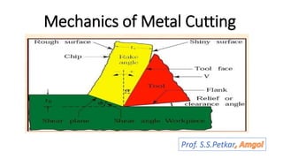
- 2. Single point Cutting tool Nomenclature Prof. S.S.Petkar, Amgoi
- 4. Terms and definitions Prof. S.S.Petkar, Amgoi
- 5. Chip Formation Prof. S.S.Petkar, Amgoi
- 7. Types of Chips Prof. S.S.Petkar, Amgoi
- 14. Cutting tool Materials Basic Requirements • Hardness • Hot Hardness • Wear resistance • Toughness • Low friction • Better thermal characteristics- high thermal conductivity Prof. S.S.Petkar, Amgoi
- 15. Comparative properties of cutting tool materials Material Room Temperature Hardness, Ra Transverse rupture strength x 1000 MPa 540°C 760 ° C HSS 85 -87 77-82 Very low 3.8-4.5 Cast Cobalt 82-85 75-82 70-75 1.4-2.8 Carbides 89-94 80-87 70-82 To 2.4 Ceramics 94 90 87 0.5-0.4 Diamond 7000 Knoop 7000 Knoop 7000 Knoop - Prof. S.S.Petkar, Amgoi
- 16. Carbon –Tool Steel (Plain Carbon steel) • C- 0.6 – 1.5%, small amount of manganese, silicon, tungsten, molybdenum, chromium, vanadium. • Limitations- In ability to withstand high temp. more than 200°C looses hardness and cease to cut • Applications At low cutting speeds (up to 0.15m/s) for wood, aluminium, brass, magnesium. They are used for form tool making, Used for low quantity production. Prof. S.S.Petkar, Amgoi
- 17. High Speed Steel Cutting speed times more than PCS Contains tungsten,moly.,chr.,van. Very good hardness & abrasion resistance Advantages:- High hardness, hot hardness, good wear resistance, high toughness & reasonable cost • Limitations:- Hardness falls rapidly beyond 650 °C They are limited to low cutting speeds. 0.5-0.75 m/s HSS T type M type Prof. S.S.Petkar, Amgoi
- 18. Cemented Carbides • Largest % of cutting tool is used in metal cutting production • They are produced by cold compaction of Tungsten carbide powder in a binder such as cobalt. • High hot hardness, high young’s modulus • Advantages:- High toughness, high impact strength, Sustain high temperature as well as speed Limitations: Not suitable for low cutting speeds Not economical to use at low speeds Expensive in inserts shape Prof. S.S.Petkar, Amgoi
- 19. Cemented carbide Classification Cemented Carbides Lower Designation number Higher designation number P10, M10, K10 P40, K40,P50 Prof. S.S.Petkar, Amgoi
- 20. Ceramics (Al2O3) Base System Density g/cm3 Hardness Transverse rupture strength, MPa 25 °C HRA 1000° C HV Al2O3 3.98 93.9 710 50 Al2O3 +TiC 4.24 94.3 770 80 Si3N4 3.27 92.6 1100 100 Properties of Ceramic Material Prof. S.S.Petkar, Amgoi
- 21. Requirements with ceramics:- High cutting speed, Rigid machine with high spindle speed Machine rigid workpiece Adequate and uninterrupted power supply Use negative rake angle Large nose radius Avoid coolants with aluminium oxides based ceramics Prof. S.S.Petkar, Amgoi
- 22. Diamond • It is the hardest known (Knoop hardness 8000kg/mm2) • Good thermal conductivity, low friction, good wear resistance, non adherence to most material. Limitation:- High cost, possibility of oxidation in air, very high brittleness. • Applications • Used for relatively light cuts • Artificial diamonds are used in industrial application • They are used with –ve rake angle -5° Typical materials machined with diamond tools are:- Al alloys, Cu, Brass, Bronze, Carbon, graphite, plastic composites Prof. S.S.Petkar, Amgoi
- 23. CBN (Cubic Boron Nitride) • It is next in hardness only after diamond (Knoop hardness 4700 kg/mm2) • It is less reactive with steel, hard chill cast iron, cobalt based alloys • It is used to machined alloys • Expensive than cemented carbide Prof. S.S.Petkar, Amgoi
- 25. Summary of Applications Tool Material Work Material Remarks Carbon Steel Low strength, soft materials, non fe alloys, plastics Low cutting speed, Low strength material. Low/Med Alloy Steel Low strength, soft materials, non fe alloys, plastics Low cutting speed, Low strength material. HSS All materials of low and medium strength & hardness Low to medium cutting speed, Low to medium strength material. Cemented carbides All materials of low and medium strength & hardness Not suitable for low speed applications Coated Carbides CI, Alloy steels , Stainless steel, super alloys Not for titanium ,non Fe alloys, CBN Hardness alloy steel,HSS, Ni based super alloys, pure nickel, Hardened chill CI High Strength, hard materials Diamond Pure cu, Al, Al-Si alloys, cold pressed cemented carbides, rock, cement, glass, plastics Not fr machining low carbon steel, Co, Ni, Ti, Zr Prof. S.S.Petkar, Amgoi
- 26. TEMPERATUR IN METAL CUTTING Prof. S.S.Petkar, Amgoi
- 27. Temperature in Metal Cutting :(Heat Generation & Dissipation) • Heat is required to be less during operation • Efforts must be taken at operations to minimise loss of energy & Power Main cause:- 1. Friction between chip and tool :- velocity of chip, ʯ, F, N . Causes 15-25% heat Controlling points:- optimum cutting speed, depth of cut, rake angle, use of lubricants at friction points Prof. S.S.Petkar, Amgoi
- 28. 2. Frictional force between the w/p & Tool:- Causes 10 % Heat. Frictional force is expected at relieving surfaces of tool. Hence.. Side relief angle & End relief angle are required to be larger 3. Friction between outgoing chip & Workpiece: it will come into existence if chips remain undisposed from w/p. In shear plane 65-75 % heat is generated proper use of chip breakers can disconnect the chips from w/p, due to this friction can be minimised Prof. S.S.Petkar, Amgoi
- 29. Heat Dissipation • Why heat should be removed from operation?? 1. Loss of accuracy at w/p 2. Loss of cutting properties of tool 3. Loss of tool life 4. Loss of efficiency • Cooling media 1. Air in form of jet 2. Water in form of continuous flowing jet. 3. Water mixed with some oils 4. Mineral and synthetic oils Prof. S.S.Petkar, Amgoi
- 30. Regions of Heat Generation Prof. S.S.Petkar, Amgoi
- 31. There are number of methods for measuring the chip tool interface temperature. • Radiation pyrometers • Embedded thermocouples • Temperature sensitive paints • Temper colours • Indirect calorimetric technique • Tool work thermocouple Prof. S.S.Petkar, Amgoi
- 32. Tool Material, cutting speed Work Piece Material H.S.S Cemented Carbide Mild Steel 30-40 m/min 80-120 m/min Grey Cast Iron 20-30 m/min 60-90 m/min Brass 60-80 m/min 80-200 m/min Aluminium 80-120 m/min 200-300 m/min Cast Steel 15-125 m/min 40-80 m/min Prof. S.S.Petkar, Amgoi
- 34. Temperature v/s Cutting Speed • Cutting speed depends on number of variables. • Higher cutting speed results high temperature • High temperatures are likely to affect the w/p, tool properties Prof. S.S.Petkar, Amgoi
- 35. Tool Wear • Crater Wear: • It is on rake face & less circular • It doesn’t always extend to tool tip • It may end at some distance from tip • It increases the cutting forces, modifies the tool geometry • It also increases the softness at tool tip Prof. S.S.Petkar, Amgoi
- 36. Flank Wear (Wear Land) • It is on the clearance surface of the tool • It can be characterised by the length of wear land (w) • It also modifies the tool geometry • It changes the cutting parameters like depth of cut. • Tools are subjected to severe conditions 1. Metal to metal contact 2. Very high stress 3. Very high temperature 4. Very high stress gradient 5. Very high temperature gradient 6. Virgin metal Prof. S.S.Petkar, Amgoi
- 37. Progressive Crater Wear Progressive Flank Wear Prof. S.S.Petkar, Amgoi
- 38. Tool Life Criteria Weal Land (mm) Tool Material Remarks 0.75 Carbides Roughing 0.25-0.38 Carbides Finishing 1.50 HSS Roughing 0.25-0.38 HSS Finishing 0.25-0.38 Oxides Roughing & Finishing Prof. S.S.Petkar, Amgoi
- 39. Possible tool failure criteria Based on Tool Wear • Fine cracks Developing at cutting edge. • Wear land size • Crater depth, width • Combination of above two • Volume or weight of material worn off the tool • Total destruction of the tool Based on consequences of Worn Tool • Limiting value of surface finish • Limiting value of change in component size • Fixed increase in cutting force or power required to perform a cut Prof. S.S.Petkar, Amgoi
- 40. Cutting Fluids Functions • Cool the tool and workpiece • Reduce friction • Protect the work against rusting • Improve the surface finish • Wash away the chips from the cutting zone • To control the total Heat Cooling action • Cooling the tool chip interface helps in retaining original properties of tool hence increase in life • Reduction in temperature increases the shear flow stress of w/p hence decrease tool life Prof. S.S.Petkar, Amgoi
- 41. Selection of cutting fluids • Water based Emulsion • Mineral Oils • Neat oils (Mineral oil + Additives) • Cutting Fluid Selection 1. Workpiece material 2. Machining operation 3. Cutting tool material 4. Other factors Prof. S.S.Petkar, Amgoi
- 42. Cutting fluids based on Work Material Material Cutting fluid to be used Selection guidelines Gey cast Iron Soluble oils, thinner neat oils for flushing swarf and dust Al alloys Soluble oil, straight neat oil Mild steel, L. C. Steel Milky type soluble oil, neat cutting oil High Carbon steel Extreme Pressure(EP) cutting oil, milky soluble oil in some applications Alloy steels Extreme Pressure(EP) cutting oil, milky soluble oil in some applications Cu Alloys Water based fluids. For tougher alloys neat blended oil used S.S & H.R.A. High neat oil, EP Oils Prof. S.S.Petkar, Amgoi
- 43. Cutting fluids based on Tool Material Tool Material Cutting Fluid Requirements High Carbon Steel Water based coolants High speed steel For general machining water based, heavy duty work EP neat oils Non Ferrous Material Neat cutting oils are most suitable Carbides, Ceramics and diamond Water based coolants , EP based oils Prof. S.S.Petkar, Amgoi
- 44. Machineability • It is ease of machining • Depending factors:- 1. raw material 2. Volume of material being removed 3. Volume of material being removed per tool resharpening 4. The quality of the machined surface in terms of the surface texture 5. The precision at the dimensions 6. The specific power consumption (power / mm3 of material to be removed) Prof. S.S.Petkar, Amgoi
- 45. Due to complexity , machineability is expressed as a Comparative index as… Cutting speed for material for 20 min. tool life • M.I.= ----------------------------------------------------------------------------------------------- x 100 Cutting speed for free cutting steel for 20 min. tool life The various values of the M.I. for different materials are Cu- 70, AL Alloys – 300 to 1000, S.S.- 25, C-45 steel- 60, Brass -180 Prof. S.S.Petkar, Amgoi
- 46. Tool Designation • Under ASA 8-14-6-6-6-15-1/8 αb= 8, αs=14, θe= 6, θs= 6, Ce= 6, Cs=15, R=1/8 • Under ORS 0-10-6-6-8-90-1 i=0, α=10, ϒ=6, ϒ1=6, Ce=8, lambda=90, R=1 Prof. S.S.Petkar, Amgoi
- 47. Theory of Lee and Shaffer • They applied the theory of plasticity for ideal plastic material • They assumed that deformation occurred on thin shear plane • There must be a stress field within in metal chip to transmit the cutting force from shear plane to tool face •𝜑= 𝜋 4 − (𝛽 − 𝛼) Prof. S.S.Petkar, Amgoi
- 48. Cutting power • The cutting power or rate of energy consumption ,is the product of cutting speed and cutting force. • E= Fc x V • Power consumed in cutting, if Fc in Kg.f and V is in m/min Pc= 𝑭𝒄∗𝑽 𝟔𝟎∗𝟏𝟎𝟐 kW Power consumed in cutting, if Fc in N and V is in m/s Pc= 𝑭𝒄∗𝑽 𝟏𝟎𝟎𝟎 kW Prof. S.S.Petkar, Amgoi
- 49. PLOWING FORCE AND SIZE EFFECT. The resultant too force in metal cutting is distributed over the areas of the tool that contact the chip and workpiece. No cutting tool is perfectly sharp, and in the idealized picture as shown in Figure 2 the cutting edge is represented by a cylindrical surface joining the tool flank and tool face Neither the force acting on the tool edge nor the force that may act on the tool flank contributes to removal of chip and these forces will be referred to collectively as plowing force. Fp The existence of the plowing force results in certain important effects and can explain the so called size effect. This term refers to the increase in specific cutting energy Prof. S.S.Petkar, Amgoi
Editor's Notes
- Tool coatings and machinability part