
Recommended
Recommended
More Related Content
What's hot
What's hot (20)
Similar to Design of Riveted joints(Boiler joints)
Similar to Design of Riveted joints(Boiler joints) (20)
Recently uploaded
Recently uploaded (20)
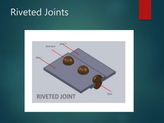
Design of Riveted joints(Boiler joints)
- 2. Table of Contents Eccentric Loaded Riveted Joint Problem Statement Design of Boiler Joints Assumptions in designing boiler joints Design of Circumferential Lap Joint for a Boiler Design of Longitudinal Butt Joint for a Boiler Design of longitudinal joint Design of Circumferential joint
- 3. Eccentric Loaded Riveted Joint When the line of action of the load does not pass through the centroid of the rivet system and thus all rivets are not equally loaded, then the joint is said to an eccentric loaded riveted joint, as shown in Fig. 9.23 (a). The eccentric results in secondary shear caused by the tendency of force to twist the joint about the centre of gravity in addition to direct shear or primary shear. Let P = Eccentric load on the joint, and e = Eccentricity of the load i.e. the distance between the line of action of the load and the centroid of the rivet system i.e. CG. The following procedure is adopted for the design of an eccentrically loaded riveted joint.
- 4. 1. First of all, find the centre of gravity G of the rivet system. Let A = Cross-sectional area of each rivet, We know that x1, x2, x3 etc. = Distances of rivets from OY, and y1, y2, y3 etc. = Distances of rivets from OX. Centroid n yyy AAA yAyAyA y n xxx AAA xAxAxA x 321 321 332211 321 321 332211
- 5. Eccentrically loaded riveted joint
- 6. 2. Introduce two forces P1 and P2 at the centre of gravity ‘G’ of the rivet system. These forces are equal and opposite to P as shown in Fig. 3. Assuming that all the rivets are of the same size, the effect of P1 = P is to produce direct shear load on each rivet of equal magnitude. Therefore, direct shear load on each rivet acting parallel to the load P. 4. The effect of P2 = P is to produce a turning moment of magnitude P × e which tends to rotate the joint about the centre of gravity ‘G’ of the rivet system in a clockwise direction. Due to the turning moment, secondary shear load on each rivet is produced. In order to find the secondary shear load, the following two assumptions are made : (a) The secondary shear load is proportional to the radial distance of the rivet under consideration from the centre of gravity of the rivet system. (b) The direction of secondary shear load is perpendicular to the line joining the centre of the rivet to the centre of gravity of the rivet system. n P Ps
- 7. 5. The primary (or direct) and secondary shear load may be added vectorially to determine the resultant shear load (R) on each rivet as shown in Fig. It may also be obtained by using the relation
- 8. θ = Angle between the primary or direct shear load (Ps) and secondary shear load (F). When the secondary shear load on each rivet is equal, then the heavily loaded rivet will be one in which the included angle between the direct shear load and secondary shear load is minimum. The maximum loaded rivet becomes the critical one for determining the strength of the riveted joint. Knowing the permissible shear stress (τ), the diameter of the rivet hole may be obtained by using the relation,
- 9. Problem A bracket in the form of a plate is fitted to a column by means of four rivets A, C and D in the same vertical line, as shown in Fig. AB = BC = CD = 60 mm. E is mid-point of BC. A load of 100 kN is applied to the bracket at a point F which is a horizontal distance of 150 m from E. The load acts at an angle of 30° to the horizontal. Determine the diameter of the rivets which are made of steel having yield stress in shear of 240 MPa. Take a factor of safety of 1.5. What would be the thickness of the plate taking an allowable bending stress of 125 MPa for the plate, assuming its total width at section ABCD as 240 mm?
- 11. Diameter of rivets Let d = Diameter of rivets. We know that direct shear load on each rivet, N n P Ps 25000 4 10100 3 EG = e = EF sin 30° = 150 × 0.5 = 75 mm ∴ Turning moment produced by the load P due to eccentricity = P. e = 100 × 103 × 75 = 7500 × 103 N-mm This turning moment is resisted by four bolts, as shown in Fig. Let FA, FB, FC and FD be the secondary shear load on the rivets, A, B, C, and D placed at distances lA, lB, lC and lD respectively from the centre of gravity of the rivet system.
- 17. Design of Boiler Joints The longitudinal joint is used to join the ends of the plate to get the required diameter of a boiler. For this purpose, a butt joint with two cover plates is used. circumferential joint is used to get the required length of the boiler. For this purpose, a lap joint with one ring overlapping the other alternately is used.
- 18. Assumptions in Designing Boiler Joints The load on the joint is equally shared by all the rivets. The assumption implies that the shell and plate are rigid and that all the deformation of the joint takes place in the rivets themselves. The tensile stress is equally distributed over the section of metal between the rivets. The shearing stress in all the rivets is uniform. The crushing stress is uniform. There is no bending stress in the rivets. The holes into which the rivets are driven do not weaken the member. The rivet fills the hole after it is driven. The friction between the surfaces of the plate is neglected.
- 19. Design of Longitudinal Butt Joint for a Boiler
- 20. Indian Boiler Regulations (I.B.R.) allow a maximum efficiency of 85% for the best joint. (c) According to I.B.R., the factor of safety should not be less than 4. The following table shows the values of factor of safety for various kind of joints in boilers.
- 23. Design of Circumferential Lap Joint for a Boiler
- 26. A steam boiler is to be designed for a working pressure of 2.5 N/mm2 with its inside diameter 1.6 m. Give the design calculations for the longitudinal and circumferential joints for the following working stresses for steel plates and rivets : In tension = 75 MPa ; In shear = 60 MPa; In crushing = 125 MPa. Draw the joints to a suitable scale.
- 27. Design of longitudinal joint
- 31. Design of circumferential joint1. The thickness of the boiler shell ( t ) and diameter of rivet hole ( d ) will be same as for longitudinal joint, i.e. t = 28 mm ; and d = 34.5 mm