
Recommended
Recommended
More Related Content
What's hot
What's hot (20)
Similar to SImple strain.pdf
Similar to SImple strain.pdf (20)
Recently uploaded
Recently uploaded (20)
SImple strain.pdf
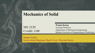
- 1. Mechanics of Solid ME 2129 Credit: 3.00 Pranto Karua Assistant Professor Department of Mechanical Engineering Khulna University of Engineering & Technology Simple Strain Stress-strain Diagram, Hook’s Law, Thermal Stress
- 2. Simple Strain 2 Introduction to Strain Different Types of Strain Stress-Strain diagram Hook’s law: Axial And Shearing Deformations Poisson’s Ratio Statically Indeterminate Members Thermal Stresses Strength of Materials (4th Edition) -Andrew Pytel, Ferdinand L. Singer Reference Books Mechanics of Materials (10th Edition) -Russell C. Hibbeler
- 3. Strain 3 When a body is subjected to some external force, there is some change in the dimension of the body. The ratio of change in dimension of body to its original dimension is called as strain. 𝜀 = 𝛿 𝐿 where δ is the deformation and L is the original length, thus ε is dimensionless. Simple strain can be classified as tensile strain, compressive strain, shear strain, volumetric strain.
- 4. Tensile Strain 4 Tensile strain is the ratio of the increase in length to its original length. Tensile strain = Increase in length, (l – lo) / Original length, lo
- 5. Compressive Strain 5 Compressive strain is the ratio of the decrease in length to its original length. Compressive strain = Decrease in length, (lo – l) / Original length, lo
- 6. Stress-Strain Diagram 6 Suppose a metal specimen is placed in a tension-compression testing machine. As the axial load is gradually increased in increments, the total elongation is measured at each increment of the load and this is continued until failure of the specimen takes place. Knowing the original cross-sectional area and length of the specimen, the normal stress σ and the strain ε can be obtained. The graph of these quantities with the stress σ along the y-axis and the strain ε along the x-axis is called the stress-strain diagram. Stress-Strain diagram differs in form for various materials. Metallic engineering materials are classified as either ductile or brittle materials.
- 7. 7 A ductile material is one having relatively large tensile strains up to the point of rupture like structural steel and aluminum. And brittle materials has a relatively small strain up to the point of rupture like cast iron and concrete. Fig 1.1: S.S.D for ductile material (Mild Steel) Fig 1.2: S.S.D for brittle material (Cast Iron) Stress-Strain Diagram
- 8. Stress-Strain Diagram In figure 1.1, there exists a linear relationship between the elongation and the axial force up to the point P, which is termed as proportional limit. Hooke's Law states that within the proportional limit, the stress is directly proportional to strain. This relationship can be expressed as where σ is the stress, ε is the strain and the constant of proportionality, k is called the Modulus of Elasticity, E or Young’s Modulus and is equal to the slope of the stress-strain diagram from O to P. Thus, the relationship can be written, σ = E ε 8 σ ∝ ε or σ = k ε
- 9. Stress-Strain Diagram: Hook’s Law Elastic Limit The elastic limit is the limit beyond which the material will no longer go back to its original shape when the load is removed, or it is the maximum stress that may be developed such that there is no permanent or residual deformation when the load is entirely removed. The region in stress-strain diagram from P to E is called the elastic range. The region from E to Y is called the plastic range. Yield Point Yield point is the point at which the material will have an appreciable elongation or yielding without any increase in load. 9
- 10. Stress-Strain Diagram: Hook’s Law Ultimate Strength The maximum ordinate in the stress-strain diagram is the ultimate strength or tensile strength. Rapture Strength Rapture strength is the strength of the material at rupture. This is also known as the breaking strength. 10
- 11. Stress-Strain Diagram: Mild Steel Figure 1.3: S.S.D. for mild steel 11
- 12. Hook’s Law: Axial and Shearing Stress Axial Deformations Axial forces cause axial deformations. From Hook’s Law, we get If σ is replaced by its equivalent P/A and ε is replaced by 𝛿/L, then σ = E ε 𝑃 𝐴 = 𝐸 𝛿 𝐿 Hence, we get 𝛿 = 𝜎𝐿 𝐸 Where, = 𝑃𝐿 𝐴𝐸 𝑃 = Axial load 𝐴 = Cross sectional area 𝐸 = Modulus of elasticity 𝛿 = Axial deformations 𝐿 = Length 12
- 13. Hook’s Law: Axial and Shearing Stress Shearing Deformations Shearing forces cause shearing deformations. In shearing deformations, an element undergoes a change in its shape such as from a rectangle to a parallelogram without any change in its length. Assuming Hook’s Law to apply shear, 𝜏 = 𝐺𝛾 Where, If 𝜏 is replaced by its equivalent V/As and 𝛾 is replaced by 𝛿𝑠/L, then 𝑉 = Axial load As = Cross sectional area 𝐺 = Modulus of rigidity 𝛿𝑠 = Shearing deformations 𝐿 = Length 𝑉 As = 𝐺 𝛿𝑠 𝐿 Hence, we get 𝛿𝑠 = 𝑉𝐿 𝐴𝑠𝐺 13
- 14. Problems 14 Problem 211 A bronze bar is fastened between a steel bar and an aluminum bar as shown in figure. Axial loads are applied at the positions indicated. Find the largest value of P that will not exceed an overall deformation of 3.0 mm, or the following stresses: 140 MPa in the steel, 120 MPa in the bronze, and 80 MPa in the aluminum. Assume that the assembly is suitably braced to prevent buckling. Use Est = 200 GPa, Eal = 70 GPa, and Ebr = 83 GPa.
- 15. Problems 15 Problem 212 The rigid bar ABC shown in figure is hinged at A and supported by a steel rod at B. Determine the largest load P that can be applied at C if the stress in the steel rod is limited to 30 ksi and the vertical movement of end C must not exceed 0.10 in. Try yourself
- 16. Problems 16 Problem 213 The rigid bar AB, attached to two vertical rods as shown in figure, is horizontal before the load P is applied. Determine the vertical movement of P if its magnitude is 50 kN.
- 17. Problems 17 Problem 214 Try yourself The rigid bars AB and CD shown in figure are supported by pins at A and C and the two rods. Determine the maximum force P that can be applied as shown if its vertical movement is limited to 5 mm. Neglect the weights of all members.
- 18. Problems 18 Problem 215 A uniform concrete slab of total weight W is to be attached, as shown in figure, to two rods whose lower ends are on the same level. Determine the ratio of the areas of the rods so that the slab will remain level.
- 19. Poisson’s Ratio 19 When a bar is subjected to a tensile loading there is an increase in length of the bar in the direction of the applied load, but there is also a decrease in a lateral dimension perpendicular to the load. The ratio of the sidewise deformation (or strain) to the longitudinal deformation (or strain) is called the Poisson's ratio and is denoted by ν. The elongation in the x direction is accompanied by a contraction in the other directions.
- 20. Poisson’s Ratio 20 Poisson’s ratio can be expressed as 𝑣 = − 𝜀𝑦 𝜀𝑥 = − 𝜀𝑧 𝜀𝑥 where εx is strain in the x-direction and εy and εz are the strains in the perpendicular direction. The negative sign indicates a decrease in the transverse dimension when εx is positive. If an element is subjected simultaneously by tensile stresses σx and σy, in the x and y directions, the strain in the x direction is σx/E and the strain in the y direction is σy/E. Simultaneously, the tensile stress σy will produce a lateral contraction on the x direction of the amount -ν εy or -ν 𝜎𝑦 𝐸 . The resulting strain in the x direction will be 𝜀𝑥 = 𝜎𝑥 𝐸 − 𝑣 𝜎𝑦 𝐸
- 21. Poisson’s Ratio 21 Bulk Modulus of Elasticity, K The bulk modulus of elasticity, K is a measure of a resistance of a material to change in volume without change in shape or form. It is given as 𝐾 = 𝐸 3(1 − 2𝑣 = 𝜎 Δ 𝑉 𝑉 where V is the volume and ΔV is change in volume and the ratio ΔV/V is called volumetric strain. Relationship Between E, G, and ν The relationship between modulus of elasticity E, shear modulus G and Poisson's ratio ν is: 𝐸 = 𝐺 2(1 + 𝑣 Similarly, the resulting strain in the y direction will be 𝜀𝑦 = 𝜎𝑦 𝐸 − 𝑣 𝜎𝑥 𝐸
- 22. Problems 22 Problem 222 A solid cylinder of diameter d carries an axial load P. Show that its change in diameter is 4Pν / πEd.
- 23. Problems 23 Problem 227 A 150-mm-long bronze tube, closed at its ends, is 80 mm in diameter and has a wall thickness of 3 mm. It fits without clearance in an 80-mm hole in a rigid block. The tube is then subjected to an internal pressure of 4.00 MPa. Assuming ν = 1/3 and E = 83 GPa, determine the tangential stress in the tube. Try yourself
- 24. Problems 24 Problem 233 A steel bar 50 mm in diameter and 2 m long is surrounded by a shell of a cast iron 5 mm thick. Compute the load that will compress the combined bar a total of 0.8 mm in the length of 2 m. For steel, E = 200 GPa, and for cast iron, E = 100 GPa. Try yourself
- 25. Problems 25 Problem 236 A rigid block of mass M is supported by three symmetrically spaced rods as shown in figure. Each copper rod has an area of 900 mm2; E = 120 GPa; and the allowable stress is 70 MPa. The steel rod has an area of 1200 mm2; E = 200 GPa; and the allowable stress is 140 MPa. Determine the largest mass M which can be supported. Try yourself
- 26. Problems 26 Problem 239 The rigid platform in figure has negligible mass and rests on two steel bars, each 250.00 mm long. The center bar is aluminum and 249.90 mm long. Compute the stress in the aluminum bar after the center load P = 400 kN has been applied. For each steel bar, the area is 1200 mm2 and E = 200 GPa. For the aluminum bar, the area is 2400 mm2 and E = 70 GPa. Try yourself
- 27. Problems 27 Problem 243 A homogeneous rod of constant cross section is attached to unyielding supports. It carries an axial load P applied as shown in figure. Prove that the reactions are given by R1 = Pb/L and R2 = Pa/L. Try yourself
- 28. Problems 28 Problem 244 A homogeneous bar with a cross sectional area of 500 mm2 is attached to rigid supports. It carries the axial loads P1 = 25 kN and P2 = 50 kN, applied as shown in figure. Determine the stress in segment BC. (Hint: Use the results of Prob. 243, and compute the reactions caused by P1 and P2 acting separately. Then use the principle of superposition to compute the reactions when both loads are applied.). Try yourself
- 29. Problems 29 Problem 247 Try yourself The composite bar in figure is stress-free before the axial loads P1 and P2 are applied. Assuming that the walls are rigid, calculate the stress in each material if P1 = 150 kN and P2 = 90 kN.
- 30. Problems 30 Problem 254 Try yourself As shown in figure, a rigid bar with negligible mass is pinned at O and attached to two vertical rods. Assuming that the rods were initially stress-free, what maximum load P can be applied without exceeding stresses of 150 MPa in the steel rod and 70 MPa in the bronze rod.
- 31. Problems 31 Problem 256 Try yourself Three rods, each of area 250 mm2, jointly support a 7.5 kN load, as shown in figure. Assuming that there was no slack or stress in the rods before the load was applied, find the stress in each rod. Use Est = 200 GPa and Ebr = 83 GPa.
- 32. Thermal Stress Temperature changes cause the body to expand or contract. The amount δT is given by 𝛿𝑇 = 𝛼𝐿(𝑇𝑓 − 𝑇𝑖 = 𝛼𝐿∆𝑇 where α is the coefficient of thermal expansion in m/m°C, L is the length in meter, Ti and Tf are the initial and final temperatures, respectively in °C. For steel, α = 11.25 × 10- 6 m/m°C. If temperature deformation is permitted to occur freely, no load or stress will be induced in the structure. In some cases where temperature deformation is not permitted, an internal stress is created. The internal stress created is termed as thermal stress. 𝛿𝑇 = 𝛼𝐿∆𝑇 Deformation due to temperature changes for a homogeneous rod mounted between unyielding supports can be computed as: 32
- 33. Thermal Stress From the sketch of deformations, we see that 𝛿𝑇 = 𝛿𝑃 To reattach the rod to the wall will evidently require a pull P to produce the load deformation, 𝛿𝑃. 𝛿𝑃 = 𝑃𝐿 𝐴𝐸 = 𝜎𝐿 𝐸 In equivalent terms, 𝛼𝐿∆𝑇 = 𝜎𝐿 𝐸 ∴ 𝜎 = 𝛼𝐸∆𝑇 where σ is the thermal stress in MPa, E is the modulus of elasticity of the rod in MPa. If the pull force P can’t able to reattach the wall, then free temperature contraction is equal to the sum of the load deformation and the yield of the walls. From the sketch of deformations, we see that 𝛿𝑇 = 𝛿𝑃 + Yield 𝛼𝐿∆𝑇 = 𝜎𝐿 𝐸 + Yield ∴ 33
- 34. Problems Problem 265 : A bronze bar 3 m long with a cross-sectional area of 320 mm2 is placed between two rigid walls as shown in the figure. At a temperature of -20°C, the gap Δ = 2.5 mm. Find the temperature at which the compressive stress in the bar will be 35 MPa. Use α = 18.0 × 10⁻⁶ m/(m·°C) and E = 80 GPa. 34
- 35. Problems Problem 268 : Try yourself The rigid bar ABC in figure is pinned at B and attached to the two vertical rods. Initially, the bar is horizontal and the vertical rods are stress-free. Determine the stress in the aluminum rod if the temperature of the steel rod is decreased by 40°C. Neglect the weight of bar ABC. 36
- 36. Problems Problem 271 : A rigid bar of negligible weight is supported as shown in figure. If W = 80 kN, compute the temperature change that will cause the stress in the steel rod to be 55 MPa. Assume the coefficients of linear expansion are 11.7 µm/(m·°C) for steel and 18.9 µm/(m·°C) for bronze. 35
- 37. Problems Problem 275 : Try yourself A rigid horizontal bar of negligible mass is connected to two rods as shown in figure. If the system is initially stress-free. Calculate the temperature change that will cause a tensile stress of 90 MPa in the brass rod. Assume that both rods are subjected to the change in temperature. 37
- 38. THANK YOU! Any Query prantokarua@me.kuet.ac.bd Copyright © 2023 Pranto Karua, All rights reserved.