SlideShare a Scribd company logo
1 of 1
Download to read offline
3
Content by the Mustang technical team: Ed Palmer, Process Engineering Manager,
Chung Tong, Process Engineer, John McWilliams, Sr. Piping Designer/3D Admin.,
and Tara Johnson, Marketing Communications Coordinator
Distributed in partnership with National Petrochemical & Refiners Association (NPRA)
Artwork & rendering: Beau Brown, Industrial3d.com
Graphic coordination: Chris Jones, Xenon Group | xenongroupdesign.com
Back copies of this poster may be obtained from PennWell. To order: call 713/963-6210; fax 713/963-6228;
e-mail posters@pennwell.com; or submit request to 1455 West Loop South, Suite 400, Houston, TX 77027.
Reproduction of the contents of this poster, in any manner, is prohibited without the consent of PennWell Corp. ©2008
OIL & GAS JOURNAL
1455 West Loop South, Suite 400
Houston, TX 77027
www.ogjonline.com
Editorial direction and coordination from
David Nakamura, Refining/Petrochemical Editor
Modern Refinery:
Delayed Coking
®
www.npra.org
www.urscorp.com
713-667-9162
Safe and Reliable DCU Equipment
Independent Advice.Independent Advice.
Global Reach.Global Reach.OpX – Operational Excellence CapX – Capital Excellence
Enhancing overall refinery profitability
with advanced technologies for heavy crudes.
Advanced Desalting Technology | Desalter Retrofits | Improved Waste Water Processing Solutions
Advanced Separation Technologies
For more information, contact us at: refining@natco-us.com
www.natcogroup.com
Producing Solutions
NATCO
11210 Equity Drive, Suite 100
Houston, Texas 77041
Phone: (713) 849-7500
Fax: (713) 849-8975
Delayed coking
The delayed coking process uses high temperatures to crack, or break
down, heavy hydrocarbons into more valuable, lighter products such as light
petroleum gases (LPG), gasoline, and distillates. The process is a primary one
refiners use to convert the bottom of the crude barrel.
The key benefit of delayed coking is full conversion of heavy residual oils,
such as vacuum resid, to lighter products. This allows refiners to increase
profit margins by processing lower-cost, heavier crude slates.
In some refineries, delayed cokers are also used to dispose of refinery waste
streams, particularly sludge from wastewater treatment plants. Light products
from the delayed coker are further treated in other process units to produce
more-valuable transportation fuels, such as gasoline and diesel. Petroleum
coke, a solid product similar to coal, is produced as a by-product.
Most of the coke produced from delayed cokers is fuel-grade coke, which
is typically consumed in a coal-fired power plant. In some cases, however,
specialty cokes such as anode coke or needle coke, which has a much higher
value than fuel-grade coke, form the primary product.
Anode grade coke, used to manufacture electrodes for aluminum production,
isproducedfromfeedstockswithlowsulfurandmetals.Needlecokeisproduced
from low sulfur and highly aromatic feedstocks such as fluid catalytic cracker
(FCC) decant oil, which is the bottom product of the FCC product fractionator,
or coal tar pitch. Needle coke production uses higher operating pressures and
higher recycle ratios. Needle coke is mainly used to manufacture graphite
electrodes, which are used in steel arc furnaces.
Process description. Heavy oil feeds such as vacuum resid or atmospheric
reduced crude are preheated in heat exchangers 1 with coker gas oils
and then fed to the bottom section of the coker fractionator 2 . Fresh feed
combines with recycle, which is net liquid from the fractionator wash section
above the feed inlet, and is routed to the coker heaters 3 with the coker
charge pumps.
In the coker heater, the combined feed is heated to 920° F. or more to
allow the coking reaction to occur in the coke drums. High-pressure steam,
steam condensate, or boiler feed water is injected into heater coils at various
locations to increase the velocity through the tubes and therefore minimize the
amount of coke depositing on the heater tubes.
Effluent from the coker heater accumulates in insulated vessels called
coke drums 4 . The drums allow sufficient time (delayed) to thermally crack
the feed into lighter gases, naphtha, distillates, gas oil, and coke. The coking
cycle can be as short as 10 hr in a fuel-grade coker operation, which is built
to maximize throughput, or more than 24 hr (see attached table).
A lower coke drum operating pressure and less recycle will result in more
liquid and less coke produced. A modern delayed coker that maximizes liquid
yields typically has a coke drum top operating pressure of about 15 psig and a
recycle-to-feed ratio of 5% or less. Needle coker production, however, usually
demands a high pressure (about 100 psig) and a high recycle-to-feed ratio
(about 1) to achieve the desired needle coke properties.
A vapor stream of about 800° F. from the coke drum is routed to a
fractionator 2 , where it is separated into light gases, unstabilized gasoline,
distillate, heavy coker gas oil, and a recycle stream. The coker fractionator off
gas is compressed in a wet-gas compressor, which increases the pressure
of the gas up to 200 psi. This stream then goes to a gas plant 5 along with
the unstabilized gasoline, where it is further separated into dry gas, LPG, and
stabilized gasoline.
The coker gas plant is similar to an FCC unit’s gas plant and usually consists
of an absorber-stripper and debutanizer. Sour coker dry gas from the gas
plant is scrubbed with amines to remove hydrogen sulfide before it feeds the
refinery’s fuel gas system.
The sour coker LPG is treated with amine and caustic to remove hydrogen
sulfide and mercaptan sulfur to make it suitable for sale or as feedstock in
other process units such as alkylation. The gasoline, distillate, and heavy gas
oil from the delayed coker are typically hydrotreated before further processing
in other refinery units.
Drum cycle. Coke drums are typically installed in pairs, with one coker heater
for every two coke drums. The feed stream switches between these two
drums. While one drum is filling with heater effluent, the other one is stripped
with steam, quenched with water, drained, decoked, and warmed up for the
next cycle.
The table summarizes the steps and approximately how much time each
step takes in a typical coke drum cycle for fuel-grade coke operation.
The full coke drum is first purged with steam, which first flows to the
fractionator and then the blowdown drum, to strip hydrocarbons from the coke.
After the coke drum is steamed out, water is gradually introduced into the coke
drum to cool the drum and coke.
Steam produced due to vaporizing the quench water is sent to the blowdown
drum for condensation and to recover water and heavy hydrocarbons. The
quench water flow rate then increases until the coke drum is filled with water.
This water is subsequently drained from the coke drum and the top and bottom
heads of the drum are opened.
Because of safety concerns, automatic unheading devices are commonly
used. The coke in the drum is cut and removed with high-pressure water.
The empty drum is then closed, and purged and pressure tested with steam.
Vapors from the coke drum in operation are used to heat the off-line, empty
coke drum.
Hydrocarbons condensed during the drum-heating step are drained to the
blowdown drum or fractionator. When the drum is heated sufficiently, it is
ready to receive effluent from the coker heater and start the coking cycle.
Decoking system. A decoking system 6 typically consists of:
A cutting water (jet) pump 7 .
Coke-cutting equipment, which includes a cutting tool 8 , drill stem 9 ,
drilling water hose, decoking control valve, and enclosed operator shelter.
Decoking water tank 10 .
High-pressure water cuts the coke out of the drum. The cutting water pump,
which is a multi-stage centrifugal pump, takes suction from the decoking
water tank and delivers the high-pressure water through a hose to the rotary
joint. The rotary joint uses an air, hydraulic, or electric motor to rotate the
drill stem.
The discharge pressure of the cutting water pump varies according to the
size of coke drum and type of coke produced. For large-diameter coke drums,
the discharge pressure can be more than 4,000 psig.
A cutting tool, equipped with either downward-oriented, pilot hole cutting
nozzles or side-oriented cutting nozzles, is attached to the bottom of the
drill stem. First, a pilot hole is bored through the coke that has built up
in the drum with the downward-oriented nozzles. The cutting tool is then
pulled up to the top and switched to side-oriented cutting nozzles. The
cutting tool then slowly moves through the length of the coke drum to cut
out the coke.
Coke handling. Coke and cutting water from the coke drums fall into an
adjacent large concrete pit or pad.Water drained from the pit or pad is collected
in a nearby settling basin, which separates small coke particles (fines) from
the water.
Water from the settling basin is pumped back to the decoking water tank for
reuse. The decoking water tank also serves as storage for water that is used
to quench the hot coke drum.
Coke in the pit or pad remains there long enough for the water to drain.A crane
or front-end loader moves the dewatered coke to a crusher.Then a conveyor belt
typically transfers the coke to storage, railcar, ship, or other transport method. In
some units, the coke is cut directly into railcars or to a crusher and then sluiced
as a water slurry to dewatering and storage facilities.
Step Time, hr
Coking (on-line filling) 10 - 24
Steam coke drum to the fractionator 0.5 - 1
Steam coke drum to the blowdown tower 0.5 - 1
Quench and fill water to the top of coke drum 3 - 6
Drain the water from the coke drum 1 - 3
Unhead bottom and top heads 0.5
Coke cutting (decoking) 2 - 5
Rehead the coke drum, steam pressure test, purge 0.5 - 2
Drum warmup 3 - 6
Coke drum cycle
6
3
5
1
2
4
9
IMAGE COURTESY OF FLOWSERVE
7
8
4
9
10
Modern Refinery

More Related Content

What's hot

103671766 a-students-guide-to-refinery
103671766 a-students-guide-to-refinery103671766 a-students-guide-to-refinery
103671766 a-students-guide-to-refineryvijaykale1981
 
project_presentation-Original - wht_theme
project_presentation-Original - wht_themeproject_presentation-Original - wht_theme
project_presentation-Original - wht_themeShaheem TM
 
C3.2.1. Topside Separation_2020
C3.2.1. Topside Separation_2020C3.2.1. Topside Separation_2020
C3.2.1. Topside Separation_2020David Seow
 
Treatment of crude oils
Treatment of crude oilsTreatment of crude oils
Treatment of crude oilsKarnav Rana
 
C3.2.2. Topside Gas Compression_2020
 C3.2.2. Topside Gas Compression_2020 C3.2.2. Topside Gas Compression_2020
C3.2.2. Topside Gas Compression_2020David Seow
 
PRESENTATION ON INPLANT TRAINING AT MRPL
PRESENTATION ON INPLANT TRAINING AT MRPLPRESENTATION ON INPLANT TRAINING AT MRPL
PRESENTATION ON INPLANT TRAINING AT MRPLAnkit Devatwal
 
Presentation on Crude Distillation Unit (CDU)
Presentation on Crude Distillation Unit (CDU)Presentation on Crude Distillation Unit (CDU)
Presentation on Crude Distillation Unit (CDU)Priyam Jyoti Borah
 
internship report by usama
internship report by usamainternship report by usama
internship report by usamamuhammad usama
 
Eletrochemical desalter
Eletrochemical desalterEletrochemical desalter
Eletrochemical desalterMehmoodIqbal7
 
C3.1.0. Topside Intro 2020
C3.1.0. Topside Intro 2020C3.1.0. Topside Intro 2020
C3.1.0. Topside Intro 2020David Seow
 
Distillation dehydration (sieves)5
Distillation dehydration (sieves)5Distillation dehydration (sieves)5
Distillation dehydration (sieves)5Cara Mullen
 
The project of oil refinery
The project of oil refineryThe project of oil refinery
The project of oil refinerysergio014
 
Chapter 5e -_fcc_problems2
Chapter 5e -_fcc_problems2Chapter 5e -_fcc_problems2
Chapter 5e -_fcc_problems2Helena Francis
 
Chapter 5b -_cracking_ffcu
Chapter 5b -_cracking_ffcuChapter 5b -_cracking_ffcu
Chapter 5b -_cracking_ffcuHelena Francis
 

What's hot (20)

103671766 a-students-guide-to-refinery
103671766 a-students-guide-to-refinery103671766 a-students-guide-to-refinery
103671766 a-students-guide-to-refinery
 
crude oil refining process - CDU & VDU
crude oil refining process - CDU & VDUcrude oil refining process - CDU & VDU
crude oil refining process - CDU & VDU
 
Internship Report
Internship ReportInternship Report
Internship Report
 
internship report
internship reportinternship report
internship report
 
cdu and vdu unit
cdu and vdu unitcdu and vdu unit
cdu and vdu unit
 
project_presentation-Original - wht_theme
project_presentation-Original - wht_themeproject_presentation-Original - wht_theme
project_presentation-Original - wht_theme
 
C3.2.1. Topside Separation_2020
C3.2.1. Topside Separation_2020C3.2.1. Topside Separation_2020
C3.2.1. Topside Separation_2020
 
Oil Refinery - Processes
Oil Refinery - ProcessesOil Refinery - Processes
Oil Refinery - Processes
 
Treatment of crude oils
Treatment of crude oilsTreatment of crude oils
Treatment of crude oils
 
C3.2.2. Topside Gas Compression_2020
 C3.2.2. Topside Gas Compression_2020 C3.2.2. Topside Gas Compression_2020
C3.2.2. Topside Gas Compression_2020
 
PRESENTATION ON INPLANT TRAINING AT MRPL
PRESENTATION ON INPLANT TRAINING AT MRPLPRESENTATION ON INPLANT TRAINING AT MRPL
PRESENTATION ON INPLANT TRAINING AT MRPL
 
Presentation on Crude Distillation Unit (CDU)
Presentation on Crude Distillation Unit (CDU)Presentation on Crude Distillation Unit (CDU)
Presentation on Crude Distillation Unit (CDU)
 
internship report by usama
internship report by usamainternship report by usama
internship report by usama
 
Eletrochemical desalter
Eletrochemical desalterEletrochemical desalter
Eletrochemical desalter
 
C3.1.0. Topside Intro 2020
C3.1.0. Topside Intro 2020C3.1.0. Topside Intro 2020
C3.1.0. Topside Intro 2020
 
Distillation dehydration (sieves)5
Distillation dehydration (sieves)5Distillation dehydration (sieves)5
Distillation dehydration (sieves)5
 
The project of oil refinery
The project of oil refineryThe project of oil refinery
The project of oil refinery
 
2010 npra seminar, fundamentals of desalter operation
2010 npra seminar, fundamentals of desalter operation2010 npra seminar, fundamentals of desalter operation
2010 npra seminar, fundamentals of desalter operation
 
Chapter 5e -_fcc_problems2
Chapter 5e -_fcc_problems2Chapter 5e -_fcc_problems2
Chapter 5e -_fcc_problems2
 
Chapter 5b -_cracking_ffcu
Chapter 5b -_cracking_ffcuChapter 5b -_cracking_ffcu
Chapter 5b -_cracking_ffcu
 

Similar to Quick summary for delayed cokeing unit dcu

KRISHNA(200103040)_IR_PPT.pptx
KRISHNA(200103040)_IR_PPT.pptxKRISHNA(200103040)_IR_PPT.pptx
KRISHNA(200103040)_IR_PPT.pptxadityaraaj1
 
A report of the vocational training at MTPS(DVC) for mechanical only
A report of the vocational training at MTPS(DVC) for mechanical onlyA report of the vocational training at MTPS(DVC) for mechanical only
A report of the vocational training at MTPS(DVC) for mechanical onlyShobhan Biswas
 
Best steam power plant
Best steam power plant Best steam power plant
Best steam power plant Enamul Khan
 
Elective_Refining 1.pptx
Elective_Refining 1.pptxElective_Refining 1.pptx
Elective_Refining 1.pptxDexterTanabe
 
Marine Boilers and steam engineering .pptx
Marine Boilers and steam engineering .pptxMarine Boilers and steam engineering .pptx
Marine Boilers and steam engineering .pptxdevmarineacademy
 
technical-packages.pdf |Goel scientific | Canada
technical-packages.pdf |Goel scientific | Canadatechnical-packages.pdf |Goel scientific | Canada
technical-packages.pdf |Goel scientific | CanadaGoelScientific1
 
Thermal power plant seminar ppt
Thermal power plant seminar pptThermal power plant seminar ppt
Thermal power plant seminar pptvipinchaudhary45
 
Sunil- Thermal Power Plant
Sunil- Thermal Power PlantSunil- Thermal Power Plant
Sunil- Thermal Power PlantSunil8889
 
lec 6 Steam genr ME430 fall 22.pptx
lec 6 Steam genr ME430 fall 22.pptxlec 6 Steam genr ME430 fall 22.pptx
lec 6 Steam genr ME430 fall 22.pptxHaider627604
 
Introduction to chemical process industry.pptx
Introduction to chemical process industry.pptxIntroduction to chemical process industry.pptx
Introduction to chemical process industry.pptxIngridTalla1
 
Basic understanding of thermal power generation
Basic understanding of thermal power generationBasic understanding of thermal power generation
Basic understanding of thermal power generationSourav Jana
 
Overview of mejia thermal power station, DVC
Overview of mejia thermal power station, DVCOverview of mejia thermal power station, DVC
Overview of mejia thermal power station, DVCNITISHKHALKHO
 
Thermalpowerpoint 130818150844-phpapp01
Thermalpowerpoint 130818150844-phpapp01Thermalpowerpoint 130818150844-phpapp01
Thermalpowerpoint 130818150844-phpapp01Preeti Pradhan
 
Amardeep jadeja copy.ppt [autosaved]
Amardeep jadeja   copy.ppt [autosaved]Amardeep jadeja   copy.ppt [autosaved]
Amardeep jadeja copy.ppt [autosaved]Amardeep Jadeja
 

Similar to Quick summary for delayed cokeing unit dcu (20)

KRISHNA(200103040)_IR_PPT.pptx
KRISHNA(200103040)_IR_PPT.pptxKRISHNA(200103040)_IR_PPT.pptx
KRISHNA(200103040)_IR_PPT.pptx
 
A report of the vocational training at MTPS(DVC) for mechanical only
A report of the vocational training at MTPS(DVC) for mechanical onlyA report of the vocational training at MTPS(DVC) for mechanical only
A report of the vocational training at MTPS(DVC) for mechanical only
 
narendra VT SIT
narendra VT SITnarendra VT SIT
narendra VT SIT
 
Best steam power plant
Best steam power plant Best steam power plant
Best steam power plant
 
Elective_Refining 1.pptx
Elective_Refining 1.pptxElective_Refining 1.pptx
Elective_Refining 1.pptx
 
Marine Boilers and steam engineering .pptx
Marine Boilers and steam engineering .pptxMarine Boilers and steam engineering .pptx
Marine Boilers and steam engineering .pptx
 
technical-packages.pdf |Goel scientific | Canada
technical-packages.pdf |Goel scientific | Canadatechnical-packages.pdf |Goel scientific | Canada
technical-packages.pdf |Goel scientific | Canada
 
Thermal power plant seminar ppt
Thermal power plant seminar pptThermal power plant seminar ppt
Thermal power plant seminar ppt
 
PRESENTATION ON HYDROGEN GAS PRODUCTION BY PARTIAL OXIDATION OF HEAVY FUEL OI...
PRESENTATION ON HYDROGEN GAS PRODUCTION BY PARTIAL OXIDATION OF HEAVY FUEL OI...PRESENTATION ON HYDROGEN GAS PRODUCTION BY PARTIAL OXIDATION OF HEAVY FUEL OI...
PRESENTATION ON HYDROGEN GAS PRODUCTION BY PARTIAL OXIDATION OF HEAVY FUEL OI...
 
Sunil- Thermal Power Plant
Sunil- Thermal Power PlantSunil- Thermal Power Plant
Sunil- Thermal Power Plant
 
lec 6 Steam genr ME430 fall 22.pptx
lec 6 Steam genr ME430 fall 22.pptxlec 6 Steam genr ME430 fall 22.pptx
lec 6 Steam genr ME430 fall 22.pptx
 
Introduction to chemical process industry.pptx
Introduction to chemical process industry.pptxIntroduction to chemical process industry.pptx
Introduction to chemical process industry.pptx
 
Basic understanding of thermal power generation
Basic understanding of thermal power generationBasic understanding of thermal power generation
Basic understanding of thermal power generation
 
thermalcracking.pptx
thermalcracking.pptxthermalcracking.pptx
thermalcracking.pptx
 
Presentation On Boiler Analysis
Presentation On Boiler AnalysisPresentation On Boiler Analysis
Presentation On Boiler Analysis
 
Article - 2012 PTQ Q1
Article - 2012 PTQ Q1Article - 2012 PTQ Q1
Article - 2012 PTQ Q1
 
sugar mill ss.pptx
sugar mill ss.pptxsugar mill ss.pptx
sugar mill ss.pptx
 
Overview of mejia thermal power station, DVC
Overview of mejia thermal power station, DVCOverview of mejia thermal power station, DVC
Overview of mejia thermal power station, DVC
 
Thermalpowerpoint 130818150844-phpapp01
Thermalpowerpoint 130818150844-phpapp01Thermalpowerpoint 130818150844-phpapp01
Thermalpowerpoint 130818150844-phpapp01
 
Amardeep jadeja copy.ppt [autosaved]
Amardeep jadeja   copy.ppt [autosaved]Amardeep jadeja   copy.ppt [autosaved]
Amardeep jadeja copy.ppt [autosaved]
 

Recently uploaded

Heart Disease Prediction using machine learning.pptx
Heart Disease Prediction using machine learning.pptxHeart Disease Prediction using machine learning.pptx
Heart Disease Prediction using machine learning.pptxPoojaBan
 
DATA ANALYTICS PPT definition usage example
DATA ANALYTICS PPT definition usage exampleDATA ANALYTICS PPT definition usage example
DATA ANALYTICS PPT definition usage examplePragyanshuParadkar1
 
Sachpazis Costas: Geotechnical Engineering: A student's Perspective Introduction
Sachpazis Costas: Geotechnical Engineering: A student's Perspective IntroductionSachpazis Costas: Geotechnical Engineering: A student's Perspective Introduction
Sachpazis Costas: Geotechnical Engineering: A student's Perspective IntroductionDr.Costas Sachpazis
 
GDSC ASEB Gen AI study jams presentation
GDSC ASEB Gen AI study jams presentationGDSC ASEB Gen AI study jams presentation
GDSC ASEB Gen AI study jams presentationGDSCAESB
 
Biology for Computer Engineers Course Handout.pptx
Biology for Computer Engineers Course Handout.pptxBiology for Computer Engineers Course Handout.pptx
Biology for Computer Engineers Course Handout.pptxDeepakSakkari2
 
An experimental study in using natural admixture as an alternative for chemic...
An experimental study in using natural admixture as an alternative for chemic...An experimental study in using natural admixture as an alternative for chemic...
An experimental study in using natural admixture as an alternative for chemic...Chandu841456
 
Arduino_CSE ece ppt for working and principal of arduino.ppt
Arduino_CSE ece ppt for working and principal of arduino.pptArduino_CSE ece ppt for working and principal of arduino.ppt
Arduino_CSE ece ppt for working and principal of arduino.pptSAURABHKUMAR892774
 
Effects of rheological properties on mixing
Effects of rheological properties on mixingEffects of rheological properties on mixing
Effects of rheological properties on mixingviprabot1
 
CCS355 Neural Network & Deep Learning Unit II Notes with Question bank .pdf
CCS355 Neural Network & Deep Learning Unit II Notes with Question bank .pdfCCS355 Neural Network & Deep Learning Unit II Notes with Question bank .pdf
CCS355 Neural Network & Deep Learning Unit II Notes with Question bank .pdfAsst.prof M.Gokilavani
 
Past, Present and Future of Generative AI
Past, Present and Future of Generative AIPast, Present and Future of Generative AI
Past, Present and Future of Generative AIabhishek36461
 
Churning of Butter, Factors affecting .
Churning of Butter, Factors affecting  .Churning of Butter, Factors affecting  .
Churning of Butter, Factors affecting .Satyam Kumar
 
CCS355 Neural Networks & Deep Learning Unit 1 PDF notes with Question bank .pdf
CCS355 Neural Networks & Deep Learning Unit 1 PDF notes with Question bank .pdfCCS355 Neural Networks & Deep Learning Unit 1 PDF notes with Question bank .pdf
CCS355 Neural Networks & Deep Learning Unit 1 PDF notes with Question bank .pdfAsst.prof M.Gokilavani
 
pipeline in computer architecture design
pipeline in computer architecture  designpipeline in computer architecture  design
pipeline in computer architecture designssuser87fa0c1
 
Electronically Controlled suspensions system .pdf
Electronically Controlled suspensions system .pdfElectronically Controlled suspensions system .pdf
Electronically Controlled suspensions system .pdfme23b1001
 
UNIT III ANALOG ELECTRONICS (BASIC ELECTRONICS)
UNIT III ANALOG ELECTRONICS (BASIC ELECTRONICS)UNIT III ANALOG ELECTRONICS (BASIC ELECTRONICS)
UNIT III ANALOG ELECTRONICS (BASIC ELECTRONICS)Dr SOUNDIRARAJ N
 
IVE Industry Focused Event - Defence Sector 2024
IVE Industry Focused Event - Defence Sector 2024IVE Industry Focused Event - Defence Sector 2024
IVE Industry Focused Event - Defence Sector 2024Mark Billinghurst
 
Risk Assessment For Installation of Drainage Pipes.pdf
Risk Assessment For Installation of Drainage Pipes.pdfRisk Assessment For Installation of Drainage Pipes.pdf
Risk Assessment For Installation of Drainage Pipes.pdfROCENODodongVILLACER
 
Artificial-Intelligence-in-Electronics (K).pptx
Artificial-Intelligence-in-Electronics (K).pptxArtificial-Intelligence-in-Electronics (K).pptx
Artificial-Intelligence-in-Electronics (K).pptxbritheesh05
 

Recently uploaded (20)

Heart Disease Prediction using machine learning.pptx
Heart Disease Prediction using machine learning.pptxHeart Disease Prediction using machine learning.pptx
Heart Disease Prediction using machine learning.pptx
 
DATA ANALYTICS PPT definition usage example
DATA ANALYTICS PPT definition usage exampleDATA ANALYTICS PPT definition usage example
DATA ANALYTICS PPT definition usage example
 
Sachpazis Costas: Geotechnical Engineering: A student's Perspective Introduction
Sachpazis Costas: Geotechnical Engineering: A student's Perspective IntroductionSachpazis Costas: Geotechnical Engineering: A student's Perspective Introduction
Sachpazis Costas: Geotechnical Engineering: A student's Perspective Introduction
 
GDSC ASEB Gen AI study jams presentation
GDSC ASEB Gen AI study jams presentationGDSC ASEB Gen AI study jams presentation
GDSC ASEB Gen AI study jams presentation
 
Biology for Computer Engineers Course Handout.pptx
Biology for Computer Engineers Course Handout.pptxBiology for Computer Engineers Course Handout.pptx
Biology for Computer Engineers Course Handout.pptx
 
An experimental study in using natural admixture as an alternative for chemic...
An experimental study in using natural admixture as an alternative for chemic...An experimental study in using natural admixture as an alternative for chemic...
An experimental study in using natural admixture as an alternative for chemic...
 
Arduino_CSE ece ppt for working and principal of arduino.ppt
Arduino_CSE ece ppt for working and principal of arduino.pptArduino_CSE ece ppt for working and principal of arduino.ppt
Arduino_CSE ece ppt for working and principal of arduino.ppt
 
Effects of rheological properties on mixing
Effects of rheological properties on mixingEffects of rheological properties on mixing
Effects of rheological properties on mixing
 
CCS355 Neural Network & Deep Learning Unit II Notes with Question bank .pdf
CCS355 Neural Network & Deep Learning Unit II Notes with Question bank .pdfCCS355 Neural Network & Deep Learning Unit II Notes with Question bank .pdf
CCS355 Neural Network & Deep Learning Unit II Notes with Question bank .pdf
 
Past, Present and Future of Generative AI
Past, Present and Future of Generative AIPast, Present and Future of Generative AI
Past, Present and Future of Generative AI
 
Churning of Butter, Factors affecting .
Churning of Butter, Factors affecting  .Churning of Butter, Factors affecting  .
Churning of Butter, Factors affecting .
 
CCS355 Neural Networks & Deep Learning Unit 1 PDF notes with Question bank .pdf
CCS355 Neural Networks & Deep Learning Unit 1 PDF notes with Question bank .pdfCCS355 Neural Networks & Deep Learning Unit 1 PDF notes with Question bank .pdf
CCS355 Neural Networks & Deep Learning Unit 1 PDF notes with Question bank .pdf
 
pipeline in computer architecture design
pipeline in computer architecture  designpipeline in computer architecture  design
pipeline in computer architecture design
 
Electronically Controlled suspensions system .pdf
Electronically Controlled suspensions system .pdfElectronically Controlled suspensions system .pdf
Electronically Controlled suspensions system .pdf
 
UNIT III ANALOG ELECTRONICS (BASIC ELECTRONICS)
UNIT III ANALOG ELECTRONICS (BASIC ELECTRONICS)UNIT III ANALOG ELECTRONICS (BASIC ELECTRONICS)
UNIT III ANALOG ELECTRONICS (BASIC ELECTRONICS)
 
IVE Industry Focused Event - Defence Sector 2024
IVE Industry Focused Event - Defence Sector 2024IVE Industry Focused Event - Defence Sector 2024
IVE Industry Focused Event - Defence Sector 2024
 
Risk Assessment For Installation of Drainage Pipes.pdf
Risk Assessment For Installation of Drainage Pipes.pdfRisk Assessment For Installation of Drainage Pipes.pdf
Risk Assessment For Installation of Drainage Pipes.pdf
 
🔝9953056974🔝!!-YOUNG call girls in Rajendra Nagar Escort rvice Shot 2000 nigh...
🔝9953056974🔝!!-YOUNG call girls in Rajendra Nagar Escort rvice Shot 2000 nigh...🔝9953056974🔝!!-YOUNG call girls in Rajendra Nagar Escort rvice Shot 2000 nigh...
🔝9953056974🔝!!-YOUNG call girls in Rajendra Nagar Escort rvice Shot 2000 nigh...
 
Artificial-Intelligence-in-Electronics (K).pptx
Artificial-Intelligence-in-Electronics (K).pptxArtificial-Intelligence-in-Electronics (K).pptx
Artificial-Intelligence-in-Electronics (K).pptx
 
POWER SYSTEMS-1 Complete notes examples
POWER SYSTEMS-1 Complete notes  examplesPOWER SYSTEMS-1 Complete notes  examples
POWER SYSTEMS-1 Complete notes examples
 

Quick summary for delayed cokeing unit dcu

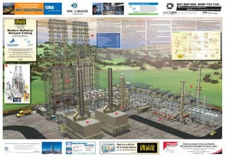
  • 1. 3 Content by the Mustang technical team: Ed Palmer, Process Engineering Manager, Chung Tong, Process Engineer, John McWilliams, Sr. Piping Designer/3D Admin., and Tara Johnson, Marketing Communications Coordinator Distributed in partnership with National Petrochemical & Refiners Association (NPRA) Artwork & rendering: Beau Brown, Industrial3d.com Graphic coordination: Chris Jones, Xenon Group | xenongroupdesign.com Back copies of this poster may be obtained from PennWell. To order: call 713/963-6210; fax 713/963-6228; e-mail posters@pennwell.com; or submit request to 1455 West Loop South, Suite 400, Houston, TX 77027. Reproduction of the contents of this poster, in any manner, is prohibited without the consent of PennWell Corp. ©2008 OIL & GAS JOURNAL 1455 West Loop South, Suite 400 Houston, TX 77027 www.ogjonline.com Editorial direction and coordination from David Nakamura, Refining/Petrochemical Editor Modern Refinery: Delayed Coking ® www.npra.org www.urscorp.com 713-667-9162 Safe and Reliable DCU Equipment Independent Advice.Independent Advice. Global Reach.Global Reach.OpX – Operational Excellence CapX – Capital Excellence Enhancing overall refinery profitability with advanced technologies for heavy crudes. Advanced Desalting Technology | Desalter Retrofits | Improved Waste Water Processing Solutions Advanced Separation Technologies For more information, contact us at: refining@natco-us.com www.natcogroup.com Producing Solutions NATCO 11210 Equity Drive, Suite 100 Houston, Texas 77041 Phone: (713) 849-7500 Fax: (713) 849-8975 Delayed coking The delayed coking process uses high temperatures to crack, or break down, heavy hydrocarbons into more valuable, lighter products such as light petroleum gases (LPG), gasoline, and distillates. The process is a primary one refiners use to convert the bottom of the crude barrel. The key benefit of delayed coking is full conversion of heavy residual oils, such as vacuum resid, to lighter products. This allows refiners to increase profit margins by processing lower-cost, heavier crude slates. In some refineries, delayed cokers are also used to dispose of refinery waste streams, particularly sludge from wastewater treatment plants. Light products from the delayed coker are further treated in other process units to produce more-valuable transportation fuels, such as gasoline and diesel. Petroleum coke, a solid product similar to coal, is produced as a by-product. Most of the coke produced from delayed cokers is fuel-grade coke, which is typically consumed in a coal-fired power plant. In some cases, however, specialty cokes such as anode coke or needle coke, which has a much higher value than fuel-grade coke, form the primary product. Anode grade coke, used to manufacture electrodes for aluminum production, isproducedfromfeedstockswithlowsulfurandmetals.Needlecokeisproduced from low sulfur and highly aromatic feedstocks such as fluid catalytic cracker (FCC) decant oil, which is the bottom product of the FCC product fractionator, or coal tar pitch. Needle coke production uses higher operating pressures and higher recycle ratios. Needle coke is mainly used to manufacture graphite electrodes, which are used in steel arc furnaces. Process description. Heavy oil feeds such as vacuum resid or atmospheric reduced crude are preheated in heat exchangers 1 with coker gas oils and then fed to the bottom section of the coker fractionator 2 . Fresh feed combines with recycle, which is net liquid from the fractionator wash section above the feed inlet, and is routed to the coker heaters 3 with the coker charge pumps. In the coker heater, the combined feed is heated to 920° F. or more to allow the coking reaction to occur in the coke drums. High-pressure steam, steam condensate, or boiler feed water is injected into heater coils at various locations to increase the velocity through the tubes and therefore minimize the amount of coke depositing on the heater tubes. Effluent from the coker heater accumulates in insulated vessels called coke drums 4 . The drums allow sufficient time (delayed) to thermally crack the feed into lighter gases, naphtha, distillates, gas oil, and coke. The coking cycle can be as short as 10 hr in a fuel-grade coker operation, which is built to maximize throughput, or more than 24 hr (see attached table). A lower coke drum operating pressure and less recycle will result in more liquid and less coke produced. A modern delayed coker that maximizes liquid yields typically has a coke drum top operating pressure of about 15 psig and a recycle-to-feed ratio of 5% or less. Needle coker production, however, usually demands a high pressure (about 100 psig) and a high recycle-to-feed ratio (about 1) to achieve the desired needle coke properties. A vapor stream of about 800° F. from the coke drum is routed to a fractionator 2 , where it is separated into light gases, unstabilized gasoline, distillate, heavy coker gas oil, and a recycle stream. The coker fractionator off gas is compressed in a wet-gas compressor, which increases the pressure of the gas up to 200 psi. This stream then goes to a gas plant 5 along with the unstabilized gasoline, where it is further separated into dry gas, LPG, and stabilized gasoline. The coker gas plant is similar to an FCC unit’s gas plant and usually consists of an absorber-stripper and debutanizer. Sour coker dry gas from the gas plant is scrubbed with amines to remove hydrogen sulfide before it feeds the refinery’s fuel gas system. The sour coker LPG is treated with amine and caustic to remove hydrogen sulfide and mercaptan sulfur to make it suitable for sale or as feedstock in other process units such as alkylation. The gasoline, distillate, and heavy gas oil from the delayed coker are typically hydrotreated before further processing in other refinery units. Drum cycle. Coke drums are typically installed in pairs, with one coker heater for every two coke drums. The feed stream switches between these two drums. While one drum is filling with heater effluent, the other one is stripped with steam, quenched with water, drained, decoked, and warmed up for the next cycle. The table summarizes the steps and approximately how much time each step takes in a typical coke drum cycle for fuel-grade coke operation. The full coke drum is first purged with steam, which first flows to the fractionator and then the blowdown drum, to strip hydrocarbons from the coke. After the coke drum is steamed out, water is gradually introduced into the coke drum to cool the drum and coke. Steam produced due to vaporizing the quench water is sent to the blowdown drum for condensation and to recover water and heavy hydrocarbons. The quench water flow rate then increases until the coke drum is filled with water. This water is subsequently drained from the coke drum and the top and bottom heads of the drum are opened. Because of safety concerns, automatic unheading devices are commonly used. The coke in the drum is cut and removed with high-pressure water. The empty drum is then closed, and purged and pressure tested with steam. Vapors from the coke drum in operation are used to heat the off-line, empty coke drum. Hydrocarbons condensed during the drum-heating step are drained to the blowdown drum or fractionator. When the drum is heated sufficiently, it is ready to receive effluent from the coker heater and start the coking cycle. Decoking system. A decoking system 6 typically consists of: A cutting water (jet) pump 7 . Coke-cutting equipment, which includes a cutting tool 8 , drill stem 9 , drilling water hose, decoking control valve, and enclosed operator shelter. Decoking water tank 10 . High-pressure water cuts the coke out of the drum. The cutting water pump, which is a multi-stage centrifugal pump, takes suction from the decoking water tank and delivers the high-pressure water through a hose to the rotary joint. The rotary joint uses an air, hydraulic, or electric motor to rotate the drill stem. The discharge pressure of the cutting water pump varies according to the size of coke drum and type of coke produced. For large-diameter coke drums, the discharge pressure can be more than 4,000 psig. A cutting tool, equipped with either downward-oriented, pilot hole cutting nozzles or side-oriented cutting nozzles, is attached to the bottom of the drill stem. First, a pilot hole is bored through the coke that has built up in the drum with the downward-oriented nozzles. The cutting tool is then pulled up to the top and switched to side-oriented cutting nozzles. The cutting tool then slowly moves through the length of the coke drum to cut out the coke. Coke handling. Coke and cutting water from the coke drums fall into an adjacent large concrete pit or pad.Water drained from the pit or pad is collected in a nearby settling basin, which separates small coke particles (fines) from the water. Water from the settling basin is pumped back to the decoking water tank for reuse. The decoking water tank also serves as storage for water that is used to quench the hot coke drum. Coke in the pit or pad remains there long enough for the water to drain.A crane or front-end loader moves the dewatered coke to a crusher.Then a conveyor belt typically transfers the coke to storage, railcar, ship, or other transport method. In some units, the coke is cut directly into railcars or to a crusher and then sluiced as a water slurry to dewatering and storage facilities. Step Time, hr Coking (on-line filling) 10 - 24 Steam coke drum to the fractionator 0.5 - 1 Steam coke drum to the blowdown tower 0.5 - 1 Quench and fill water to the top of coke drum 3 - 6 Drain the water from the coke drum 1 - 3 Unhead bottom and top heads 0.5 Coke cutting (decoking) 2 - 5 Rehead the coke drum, steam pressure test, purge 0.5 - 2 Drum warmup 3 - 6 Coke drum cycle 6 3 5 1 2 4 9 IMAGE COURTESY OF FLOWSERVE 7 8 4 9 10 Modern Refinery