1. Using cold boiler feed water for
energy recovery
Feeding membrane deaerated cold boiler feed water to appropriate units will
enable waste heat to replace substantial steam duty in a refinery
AliS¸an DoGˇan
Turkish Petroleum Refineries Corporation
Steam at different pressure
levels is used for many
purposes in refineries,
including power production
(steam turbines), heating, steam
tracing, stripping, atomising
and deaeration. Steam is
produced from fired utility boil-ers,
cogeneration units (gas
turbine HRSGs), furnace waste
heat boilers, product rundowns,
column refluxes and so on by
adding heat to supplied boiler
feed water. Boiler feed water is
conventionally supplied by
deaerators, where steam is used
to heat water to saturation
conditions at a certain pressure
to strip dissolved oxygen, with
the aim of preventing corrosion
in steam production units. In
this article, the benefits of
providing cold boiler feed water
from membrane deaerators to
steam-producing or water-heat-ing
waste heat streams will be
explained, with some typical
examples for an oil refinery.
Membrane deaerators
Membrane deaerator technology
is used for degassing liquids
around the world. They are
widely used for removing
oxygen from water, as well as
for carbon dioxide removal.
They have displaced the
vacuum tower, forced draft
deaerator and oxygen scaven-gers
for over 20 years.
Membrane contactors are used
extensively for the deaeration of
liquids in the microelectronics,
pharmaceutical, power (boiler
feed water), food and beverage,
industrial, photographic, ink
and analytical markets. A trial
study of the scope of a heat
recovery project has been
carried out within a refinery,
where the aim of the project
was to decide whether this tech-nology
should be used
extensively for the deaeration of
boiler feed water, together with
existing conventional steam
deaerators.
Membrane deaerator systems
consist of membrane contactors
combined in series, parallel or
both, designed according to the
water flow, pressure drop limita-tions
and oxygen concentration
needed at the outlet of the
system. The contactors work on
the basic principle of letting only
gas (oxygen) molecules pass to
the other side of membranes,
where a vacuum is applied via a
vacuum pump and sweep gas
(high-purity nitrogen) is
supplied. Oxygen molecules in
the water side have a high
partial pressure compared to the
vacuum side, so they tend to
pass through the hydrophobic
membranes. Here, high-purity
sweep gas is introduced to the
vacuum side to prevent oxygen
from concentrating in the
vacuum side, which sustains the
mass transfer efficiency (partial
pressure difference).
The maximum oxygen
concentration requirement for
boiler feed water in this scenario
is 7 ppb. However, 1 ppb was
targeted when selecting the
configuration for this project (to
be on the safe side). The purity
of the sweep gas nitrogen has
critical importance when select-ing
the best configuration
because it obviously has to
contain a minimum amount of
oxygen. In this case, the refinery
has a high-purity nitrogen ring
(99.99 vol%) which is mainly
consumed by reformers and
other processes that need high-purity
nitrogen. Nitrogen
consumption by the membranes
is very low (~10 Nm3/h, of
course depending on water flow
and oxygen concentration
www.eptq.com PTQ Q1 2012 1
2. temperature. A high tempera-ture
is good for efficient oxygen
removal; however, another
important point is that tempera-tures
above 60°C are not
desirable for the membranes, as
they may be damaged at such
temperatures, depending on the
operating pressure. The
demineralised water system
pressure in this case is 6–8 kg/
cm2g, which can easily be
decreased to 5 kg/cm2g or less
with the appropriate valves.
The advantages of the
membrane deaerator system,
including low investment and
operating costs and relatively
small size, make it an appropri-ate
selection for the cold boiler
feed water heat recovery project.
Membrane deaerator systems
can be purchased from various
OEM firms.
Case 1
Energy recovery from a
hydrocracker hydrogen
production unit
Waste heat from the hydroc-racker
hydrogen steam
reformer furnace is one of the
main steam producers from a
furnace waste heat boiler.
Approximately 90–120 t/h of
38 kg/cm2g steam is produced
from furnace waste heat,
depending on the unit’s work-ing
capacity. Boiler feed water
is supplied at 55 kg/cm2g and
125°C, and this is pumped from
the deaerator at the utility
production unit. Boiler feed
water is first heated by the shift
converter outlet raw hydrogen
stream, which has impurities
such as water vapour (over 40
wt%), CO, CO2, CH4 and N2.
After heating boiler feed water,
this hydrogen stream is than
cooled down further by air and
cooling water to get rid of
Raw gas
to H/E
67587 kg/hr
260.0°C
24.6 kg/cm2
BFW to H/E
118000 kg/hr
125.0°C
55.0 kg/cm2
BFW to steam
generator
118000 kg/hr
185.8°C
54.3 kg/cm2
E-203
Raw gas
to 1. drum
67587 kg/hr
157.9°C
24.4 kg/cm2
Figure 1 Hydrogen unit boiler feed water heating (before cold BFW)
targeted) when compared to
process needs (in the range of
several thousand Nm3/h) and
therefore does not have a nega-tive
effect on the refinery
nitrogen balance.
Nitrogen is purchased by the
refinery and delivered by trucks,
which periodically supply high-purity
nitrogen to the main
tanks in the refinery nitrogen
system (ring). In a refinery with-out
an available nitrogen ring, a
nitrogen tank, sized according
to the capacity of the system,
will be needed. This can be
periodically filled with the
nitrogen provided by trucks.
The other needs for the system
are a small amount of electricity
and cooling water for the
vacuum pump system, which
are easily accessible in the refin-ery
configuration.
E-205
Raw gas
to 1. cooler
61242 kg/hr
157.9°C
24.4 kg/cm2
C-207
Condensate
to stripper
6345 kg/hr
157.9°C
24.4 kg/cm2
Raw gas
to 2. cooler
61242 kg/hr
55.0°C
24.2 kg/cm2
E-206
Raw gas
to 2. drum
61242 kg/hr
28.0°C
24.1 kg/cm2
Hydrogen
from 2. drum
39245 kg/hr
28.0°C
24.1 kg/cm2
Condensate
to stripper
21996 kg/hr
28.0°C
24.1 kg/cm2
C-208
Water temperature at the
membranes is another point of
importance in the system’s
configuration. The level of
oxygen dissolved in water
depends on the temperature of
the water. The solubility of
gases decreases with increasing
temperature. Usually, at atmos-pheric
temperatures, ~6 ppm
(6000 ppb) of oxygen is
dissolved in water. Depending
on the water temperature, solu-bility
can be between 5 and 8
ppm. Therefore, depending on
the water temperature, the
membrane system load changes.
In this project’s scenario,
demineralised water is heated
by condensate drum flash
vapour and the temperature to
the membrane deaerator system
will change between 30 and
50°C, depending on the ambient
2 PTQ Q1 2012 www.eptq.com
3. water and dissolved gases.
Condensate is taken from hot
and cold condensate drums,
then the steam is stripped of its
dissolved gases and sent back
to the utility production unit.
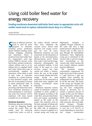
The boiler feed water heating
scheme prior to the hydrogen
reformer furnace steam genera-tor
inlet is shown in Figure 1.
For the most part, the latent
heat of condensation of water
vapour in the raw hydrogen
stream is given to the boiler
feed water to boost steam
production. A portion of
condensate recovered from this
used heat is taken from the hot
condensate drum, while the rest
of the heat is wasted to air and
cooling water. In this layout, 7.4
Gcal/h is recovered by heating
boiler feed water, while 17.4
Gcal/h is wasted.
In the current project, cold
boiler feed water (30–50°C) will
be supplied from the membrane
deaerators to this unit through
existing feed water pumps. The
driving force for heat transfer
will be increased in exchanger
E-203 (see Figure 1) and more
latent heat of condensation will
be recovered. In this way, steam
used in the deaerators is saved
and water is heated by waste
heat.
The initial projected layout for
50°C feed water temperature is
shown in Figure 2. The energy
recovered in E203 increases to
14.6 Gcal/h. Some 7.2 Gcal/h of
net energy is saved by provid-ing
cold feed water to this
exchanger and recovering more
heat of condensation in the raw
gas stream. In other words, 118
t/h of boiler feed water at 50°C
does not need to be heated to
125°C with steam in the deaera-tor.
This is equal to ~8.8 Gcal/h
steam duty saving in the
Raw gas
to H/E
67587 kg/hr
260.0°C
24.6 kg/cm2
BFW to H/E
118000 kg/hr
50.0°C
55.0 kg/cm2
BFW to steam
generator
118000 kg/hr
172.9°C
54.3 kg/cm2
E-203
Raw gas
to 1. drum
67587 kg/hr
134.4°C
24.4 kg/cm2
Figure 2 Hydrogen unit cold boiler feed water heating
deaerator according to the
simple formula:
Q=m*cp*dt.
However, because the heat
exchanger exit temperature
(waste heat steam generator
economiser inlet) is a little
lower, a portion of this saving is
lost and a net 7.2 Gcal/h is
saved.
This heat recovery may be
increased further by adding
some area to the heat exchanger,
making up for the lost portion
of heat recovery. For example,
33% additional surface area in
E-203 increases the recovered
energy by 1.1 Gcal/h.
Other side benefits of this
project are electricity savings
from air cooler fans and cooling
water savings, as with any other
process heat recovery project.
The other important saving is
E-205
Raw gas
to 1. cooler
49225 kg/hr
134.4°C
24.4 kg/cm2
C-207
Condensate
to stripper
18362 kg/hr
134.4°C
24.4 kg/cm2
Raw gas
to 2. cooler
49225 kg/hr
55.0°C
24.2 kg/cm2
E-206
Raw gas
to 2. drum
49225 kg/hr
28.0°C
24.1 kg/cm2
Hydrogen
from 2. drum
39284 kg/hr
28.0°C
24.1 kg/cm2
Condensate
to stripper
9941 kg/hr
28.0°C
24.1 kg/cm2
C-208
the stripping steam from the
condensate CO2 stripper. The
overall temperature of the total
condensate from two drums
increases, thus decreasing the
CO2 solubility, which reduces
the need for stripping steam.
Case 2
Energy recovery from a gas
turbine heat recovery steam
generator
Boiler feed water to a gas
turbine HRSG is provided from
the same header to the oil-fired
utility boilers. The water
temperature is kept above 140°C
to prevent sulphuric acid corro-sion
in the boiler economisers.
However, only natural gas is
fired in the gas turbine and
there is no risk of sulphuric acid
corrosion in the HRSG, so cold
water can be fed to the econo-miser.
The only concern is to
www.eptq.com PTQ Q1 2012 3
4. keep the temperature above
water dew point. In this way,
the driving force for heat trans-fer
will be increased in the
economiser and more heat will
be recovered during feed water
preheating. Steam used in the
deaerator to heat the water will
be replaced by waste heat.
Initial conditions are 69.8 t/h
of 68 kg/cm2g steam production
and the stack temperature is
233°C. According to trial and
error calculations, if water is
supplied at 50°C, net heat recov-ered
from the exhaust gas
increases by 6 Gcal/h. In fact,
the steam saving for boiler feed
water heating is approximately
7.5 Gcal/h. However, since the
economiser outlet temperature
to the steam drum is lower (the
approach temperature is higher),
there is a steam production loss
of ~1.5 Gcal/h from the HRSG,
which decreases the net saving
to 6 Gcal/h, as stated. By
adding some additional econo-miser
area, this loss can be
compensated and more heat
will be recovered from the
exhaust gas, increasing it to 7.5
Gcal/h and more.
It is important that the water
temperature entering the econo-miser
should be kept above the
water dew point of the exhaust
gas. This is done by taking some
water from the existing hot
boiler feed water line and
setting the temperature to the
HRSG above 50°C.
Other cases
Other potential users of cold
boiler feed water are product
rundown or column reflux
steam producers (or boiler feed
water heaters), which are placed
before air coolers, reactor efflu-ent
streams before air coolers,
and so on. For example, steam
production from vacuum resi-due
or other product rundowns,
and steam production/boiler
feed water heating in column
reflux streams are common in
refineries. One other potential
area of application is fuel gas
(or natural gas) burning
furnaces fitted with waste heat
boilers. As in the cogeneration
examples, water can be fed cold
to these units provided its
temperature is above the water
dew point of the flue gas. Low-temperature
waste heat streams
can also be used for boiler feed
water heating purposes, to boost
steam production in process
plants.
The configuration of refinery
steam and electricity production
is important when calculating
the corresponding cash benefits
of this project. After calculating
the duty and amount of steam
savings from the waste heat
sources, we shall look at the
overall steam and electricity
balance to calculate the real cash
income of the project. It is obvi-ous
that large amounts of
low-pressure deaerator steam
will be saved. In the refinery
where the project is being
applied, low-pressure steam is
extracted from electricity-gener-ating
turbo alternators and
process rotary equipment
turbines. Higher-pressure
turbine steam is produced via
fuel-burning boilers. In addi-tion,
there are the gas turbine
cogeneration unit and condens-ing
turbines already mentioned.
In this scenario, low-pressure
steam produced for the deaera-tors
is reduced; the net reduction
is approximately 15–25%
(depending on the season) of
the total low-pressure steam
extraction from the turbo alter-nators.
The project decreases the
turbo alternator loads, together
with the fuelled boiler steam
loads. The electricity lost from
the turbo alternators is compen-sated
by the gas turbine
cogeneration unit, which is
much more efficient. Therefore,
the overall efficiency of the elec-tricity
generation system is also
increased, accounting for some
additional fuel savings. For the
sake of simplicity, this addi-tional
duty saving is not taken
into account in this article. An
alternative scenario would be
the replacement of lost electric-ity
by condensing turbines,
which would decrease the net
energy saving delivered by the
project.
Conclusion
Within the ongoing project, by
feeding membrane deaerated
cold boiler feed water to appro-priate
units, it is expected that a
net saving of 16 Gcal/h of steam
duty will be made. This duty
will be replaced directly by
waste heat. The payback period
for the investment is less than
five months. By adding addi-tional
area to the related
exchangers, savings can be
increased to over 22 GCal/h.
Considering the benefits, the
short payback time, the possibil-ity
of implementing the project
without process unit shutdowns
and the use of newer technol-ogy,
the project is a very
important contribution to the
refinery’s energy roadmap
studies.
Alis¸an Dogˇan is a Process and Equipment
Development Supervisor in Head Office
Technical Services Management with
Turkish Petroleum Refineries Corporation
(Tüpras¸). He holds a BS in chemical
engineering from Middle East Technical
University, Ankara, Turkey.
Email: Alisan.Dogan@tupras.com.tr
4 PTQ Q1 2012 www.eptq.com