SlideShare a Scribd company logo
1 of 19
ACID REGENERATION PLANT
MAIN PROCESS
The main objective of this plant is to regenerate the spent acid which is coming from pickling .At pickling
the acid is showered at moving sheets of rusted steel due to which high amount of iron chloride become
mixed with this acid. Our plant is not only regenerating the acid upto 99% but also formed a valuable by-
product, i.e. Fe2O3.The flow diagram of the process is
MAIN FEATURES:
Thisis Pakistan’sonlyacidregenerationplantforuse insteel workspickling,hasprovidedconsiderably
processingadvantages,including:
 .Extremelylowemissionvalue.
 .The ironoxide by-producthasa highmarketvalue
 .Recoveryrate of HCl ishigherthan99%.
 .Constantacidqualityandcompositionensure uniformandhighqualitypickling.
 .Rinse waterinthe pickling line isusedinacidregenerationprocess,thusconsiderablyreducing
waste waterproduction.
 .The keydesignfeature of achievingextremelylow levelsof waste gasanddustemissionwhich
are belowcurrentlegislationlimits.
 .Adjustable acidconcentrationof regeneratedacid.
 .Independentfromchemical suppliers.
 .Automatedcontrol system.
FUEL:
Natural gas
Minimum calorific value 7400kcal/Nm3
Pressure 25 kPa.
CO2 2.485%
CH4 88.789%
N2 3.853%
RINSE WATER INDUSTRIAL WATER COMPRESSED AIR
Pressure 150kPa. Pressure 300kPa. Pressure 500kPa.
Temperature 60C Temperature 35C Dew point 10C
Fe 5g/l Hardness 200 ppm CaCO3 below minimum
HCl 15g/l Ph 7-8.2 ambient temp.
NITROGEN WASTE WATER REGENERATED ACID
Pressure 500-700kPa. Amount 250l/hr Amount 2000l/hr
Temperature ambient Cl- 25g/l Total HCl con. 25g/l
Purity 99.9% Fe++/+++ 15g/l Fe. 5g/l
MECHANICAL EQUIPMENTS USED AT ARP:
Spray roaster
1 spray unit
1 lump breaker
Rotary valve
Burner equipments
2 burners
2 uv-flame detector
1 combustion air blower
I set of burner piping
Dust separator
Cyclone separator
1 rotary valve
Pre concentrator with separator
Venturi
Separator
Absorption column
Exhaust fan
Gas cleaning system
Scrubber
Horizontal drop separator
Vertical drop separator
1 fume stack
Collecting bin
Oxide station
1 oxide bin
Gate valve
1 rotary valve
1 oxide separation filter
Oxide conveying pipes
Steel pipes
Conveying air fan
1 big bag fillng device
Storage tanks and pumps for ARP
1 tank for waste pickle liquor
1 tank for regenerated acid
1 tank for rinse water
1 tank for fresh acid
2 pumps for waste pickle liquor
2 pumps for regenerated acid
2 pumps for rinse water
1 pump for fresh acid
2 pumps for the sump pit
2 pumps for pre-concentrator
2 pumps for reactor feeding
2 pumps for absorber
2 pumps for gas scrubber
1 booster station. 2 pumps for water
Filters
1 filter for waste pickle liquor
2 filters for roaster charge
PROCESS DESCRIPTION:
OPERATION MODE:
ARPconsistof 4 modes
 No mode
 Freshwatermode
 Rinse watermode
 Waste water mode
START UP PROCEDURE:
The veryfirstthingwe have to do is to checkof leakage.Aftersatisfaction,we shall startthe suction
pumpwhichislocatedbelowthe roaster;the objective of startingthisfanistosuck all the unwanted
gaseswhichare presentinroaster,thenthe rotarypumpof lumpbreakeristurnon followedbythe
turningon of rotary pumpof venturi whichisinterlockedwiththe previouspump.
Thenopenthe industrial waterpump thenopenpreconcentratorpumpthenturnonthe circulationof
absorber,thiscause the removal of interlockonexhaustfan,simplyturniton thenstart the circulation
of scrubber. Adjustthe gasflowrate to the burners.Butonly1 burnershouldbe onbecause thisisthe
freshmode.
Aftersome hoursthe plantwouldbe tune to rinse watermode inwhich2nd
burnerwill alsobe started
and rinse waterpumpison withturningoff of ind.Waterpump.As soonthe temperature,inside the
roaster,reachedat 600oC, andthe topof the roasterreached400oC, insert1st
nozzle andstart spraying
the water.By doingthisthe temperature of the topside decreasedtocertainvalue butwill soonstart
increasing.Whentemperature of topof the roasterreacheditsset value again, insertanothernozzle
and run the plantfor several hoursonrinse mode.
Whenthe plantis switchedtowaste acidmode,we justhave to switchthe inletof separatorfromrinse
to waste acidline bysimplyopeningandclosingof waste acidand rinse waterpumprespectively.
WHAT IS ACTUALLY HAPPENING IN ARP??
In thisprocessthe spentacidis sprayatomizedintoadirectlyfiredfurnace and(bycontactwithoxygen)
and splittedintoFe2O3powder(solidphase)andHCl (gasphase).Reactiontemperaturesare inarange
of 400 to 700 degC. The gaseousHCl is absorbedinwaterto formregeneratedhydrochloricacidof
about17% strengthwhichcan be reusedforpickling.Itiscommonand attractive touse the slightly
acidicrinse waterfromthe picklinglineasabsorptionliquids.
The three basic processstepsof thisprocessare preconcentration,roastingandabsorption.Inthe
preconcentrationphase,the incomingwaste acidundergoesdirectheatandmassexchange withthe
hot exhaustgasfromthe roaster furnace.The directheatexchange isaccomplishedinaventuri
evaporatorwhere the waste acidisatomizedandturbulentlyintermixedwiththe roastgasat high
velocities.The waste gasisthuspartiallyevaporated,leavingbehindapreconcentrated waste acidtobe
usedas liquidfeedtothe sprayroastingfurnace. Inventuri 25% by volume of acidisevaporatedanditis
cooledfrom950c TO 400c and itis dedusted.
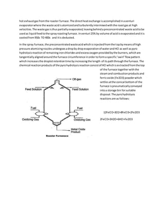
In the spray furnace,the preconcentratedwasteacidwhichisinjectedfromthe topbymeansof high
pressure atomizingnozzlesundergoesadropby dropevaporationof waterandHCl as well aspyro
hydrolysisreactionof remainingironchloridesandexcessoxygenprovidedbythe burners,whichare
tangentiallyalignedaroundthe furnace circumference inordertoforma specific‘swirl’flow pattern
whichincreasesthe dropletretentiontime byincreasingthe length of itspaththroughthe furnace.The
chemical reactionproductsof the pyrohydrolysisreactionconsistof HCl whichisextractedfromthe top
of the furnace togetherwiththe
steamand combustionproductsand
ferricoxide (Fe2O3) powderwhich
settlesatthe conical bottomof the
furnace ispneumaticallyconveyed
intoa storage bin forsuitable
disposal.The pyrohydrolysis
reactionsare as follows:
12FeCl2+3O2=8FeCl3+2Fe2O3
2FeCl3+3H2O=6HCl+Fe2O3
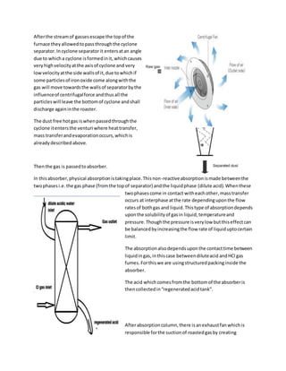
Afterthe streamof gassesescape the topof the
furnace theyallowedtopassthroughthe cyclone
separator.Incyclone separatorit entersatan angle
due to whicha cyclone isformedinit,whichcauses
veryhighvelocityatthe axisof cyclone and very
lowvelocityatthe side wallsof it,due towhichif
some particlesof ironoxide come alongwiththe
gas will move towardsthe wallsof separatorbythe
influenceof centrifugalforce andthusall the
particleswill leave the bottomof cyclone andshall
discharge againinthe roaster.
The dust free hotgas iswhenpassedthroughthe
cyclone itentersthe venturi where heattransfer,
mass transferandevaporationoccurs,whichis
alreadydescribedabove.
Thenthe gas is passedtoabsorber.
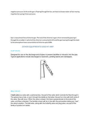
In thisabsorber,physical absorptionistakingplace.Thisnon-reactiveabsorptionismade betweenthe
twophasesi.e.the gas phase (fromthe topof separator) andthe liquidphase (dilute acid).Whenthese
twophasescome in contact witheachother,masstransfer
occurs at interphase atthe rate dependinguponthe flow
ratesof bothgas and liquid.Thistype of absorptiondepends
uponthe solubilityof gasin liquid, temperatureand
pressure.Thoughthe pressure isverylow butthiseffectcan
be balancedbyincreasingthe flow rate of liquiduptocertain
limit.
The absorptionalsodependsuponthe contacttime between
liquidingas,inthiscase betweendiluteacid andHCl gas
fumes.Forthiswe are usingstructuredpackinginside the
absorber.
The acid whichcomesfromthe bottomof the absorberis
thencollectedin“regeneratedacidtank”.
Afterabsorptioncolumn,there isanexhaustfanwhichis
responsible forthe suctionof roastedgasby creating
negative pressure.Asthe acidicgasis flowingthroughthe fan,we have toshowerwater atfast moving
impellersforsavingitfromcorrosion.
Gas is nowalmostfree of chlorine gas.The restof the chlorine ingasis thenremovedbypassingit
throughthe scrubberin whichall the chlorine isconvertedtoHCl andthe gas leavingthroughthe stack
to the atmosphere have concentrationof chlorineupto0.00%.
OTHER EQUIPMENTS USEDAT ARP
FLAP VALVE:
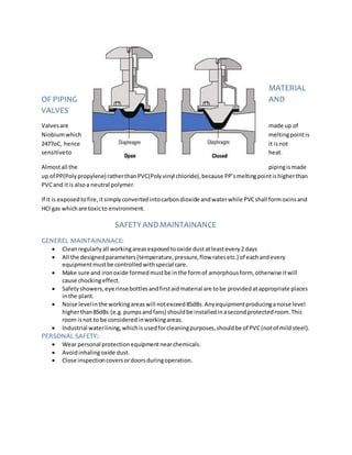
Designed for use on the discharge end of pipes to prevent backflow or intrusion into the pipe.
Typical applications include discharges to reservoirs, ponding basins and standpipes.
BALL VALVE:
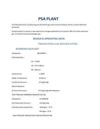
A ball valve is a valve with a spherical disc, the part of the valve which controls the flow through it.
The sphere has a hole, or port, through the middle so that when the port is in line with both ends of
the valve, flow will occur. When the valve is closed, the hole is perpendicular to the ends of the
valve, and flow is blocked. The handle or lever will be in line with the port position letting you "see"
the valve's position. The ball valve, along with the butterfly valve and plug valve, are part of the
family of quarter turn valves.
SOLENOID VALVE:
A solenoid valve is
an electromechanically operated valve. The valve is controlled by an electric current through
a solenoid: in the case of a two-port valve the flow is switched on or off; in the case of a three-port
valve, the outflow is switched between the two outlet ports. Multiple solenoid valves can be placed
together on a manifold.
Solenoid valves are the most frequently used control elements
in fluidics. Their tasks are to shut off, release, dose, distribute or
mix fluids. They are found in many application areas. Solenoids
offer fast and safe switching, high reliability, long service life,
good medium compatibility of the materials used, low control
power and compact design.
DIAPHRAGM VALVE:
Diaphragm valves can be manual or automated. Their application is generally as shut-off valves in
process systems within the industrial, food and beverage, pharmaceutical and biotech industries.
The older generation of these valves is not suited for regulating and controlling process flows,
however newer developments in this area have successfully tackled this problem.
MATERIAL
OF PIPING AND
VALVES
Valvesare made up of
Niobiumwhich meltingpointis
2477oC, hence it isnot
sensitiveto heat.
Almostall the pipingismade
up of PP(Polypropylene) ratherthanPVC(Polyvinyl chloride),because PP’smeltingpointishigherthan
PVCand itis alsoa neutral polymer.
If it is exposedtofire,itsimplyconvertedintocarbondioxide andwaterwhile PVCshall formoxinsand
HCl gas whichare toxicto environment.
SAFETYANDMAINTAINANCE
GENEREL MAINTAINANACE:
 Cleanregularlyall workingareasexposedtooxide dustatleastevery2 days
 All the designedparameters(temperature,pressure,flow ratesetc.) of eachandevery
equipmentmustbe controlled withspecial care.
 Make sure and ironoxide formedmustbe inthe formof amorphousform, otherwise itwill
cause chockingeffect.
 Safetyshowers,eye rinsebottlesandfirstaidmaterial are tobe providedatappropriate places
inthe plant.
 Noise levelinthe workingareaswill notexceed85dBs.Anyequipmentproducinganoise level
higherthan85dBs (e.g.pumpsandfans) shouldbe installedinasecondprotectedroom.This
room isnot to be consideredinworkingareas.
 Industrial waterlining,whichisusedforcleaningpurposes,shouldbe of PVC(notof mildsteel).
PERSONAL SAFETY:
 Wear personal protectionequipmentnearchemicals.
 Avoidinhalingoxide dust.
 Close inspectioncoversordoorsduringoperation.
PSA PLANT
The PSA plantof ISL is producingpure N2and H2 gas and a mixture of them, whichisusedindifferent
processes.
Compressedairisusedasa raw material fornitrogenproductionasitcontains79% of it while ammonia
gas iscracked to produce hydrogengas.
DESIGN & OPERATING DATA
PRODUCTION GAS SPECIFICATION:
NITROGEN GASPLANT:
(a)Capacity: 300 NM3/hr.
(b)Composition…
O2: 5 PPM
H2: 0.5 % (Max.)
N2: Balance
(c)DewPoint: (-) 60ºC
(d)Op.Temperature: Ambient
(e) OutLet Pressure : 5.5 Kg/Cm2g
(Before Booster)
(f) Out LetPressure : 17.0 kg/cm2g (afterBooster)
HIGH PRESSURE AMMONIA CRACKER(1W+1S):
(a)Capacity: 12 NM3/HR
(b) ProductGas Pressure. : 6.0 Kg/cm2g
(c)ProductGas composition: Hydrogen – 75 %
Nitrogen–25 %
HIGH PRESSURE CRACKEDGAS PURIFICATION SYSTEM
(a)Capacity: 12 Nm/Hr.
(b)Hydrogen: 75 %
(c)Nitrogen: 25 %
(d) DewPoint : (-) 60 °C
(e) Res.NH3: Nil
(e) Pressure atBatteryLimit: 6.0 Kg/cm2g
LOW PRESSURE AMMONIA CRACKER(1W+1S)
(a)Capacity: 60 NM3/hr.
(b) ProductGas Pressure. : 0.2 Kg/cm2g
(c)ProductGas composition:
Hydrogen – 75 %
Nitrogen– 25 %
LOW PRESSURE CRACKEDGAS PURIFICATION SYSTEM – 2
Nos.
(a)Capacity: 60 Nm/Hr.
(b)Hydrogen: 75 %
(c)Nitrogen: 25 %
(d) DewPoint : (-) 70 °C
(e) Res.NH3: Nil
(e) Pressure atBatteryLimit: 0.2 Kg/cm2g
UTILITIES CONSUMPTION:
i) CoolingWater:(ForNitrogenGasPlant& AmmoniaCracker)
Flow: (16-18) NM3/Hr.
Pressure: 2.5 Kg/cm2
Temperature: 32°C
ii) ChilledWater:(ForNitrogenGasPlant)
Flow: (2 – 3) NM3/Hr.
Pressure: 2.5 kg/cm2g
Temperature: (5 – 10) °C
iii) CompressedAir:(ForNitrogenGasPlant)
Flow: 706 CFM
Pressure: (7.0 – 7.5) Kg/Cm2
Temperature: 20°C.
iv) AmmoniaGas(For Each 12 NM3/Hr. AmmoniaCracker):
FlowfromNH3 Tank : 5 Kgs./Hr.
Pressure atinlet(AfterPRV) 6.5 Kg/Cm2
Temperature : Ambient
v) AmmoniaGas(For Each 60 NM3/Hr. AmmoniaCracker):
FlowfromNH3 Tank : 24 Kgs./Hr.
Pressure atinlet(AfterPRV): 0.8 Kg/Cm2
Temperature : Ambient
DESCRIPTIONOF PROCESSES
Nitrogen production
AIR RECEIVER:
As itis discussedabove thatnitrogenisseparatedfromair,forthisair is
compressedto7.5 bars whichis receivedbyairreceiver,alsocalledasairbuffer.Asthe compressedair,
movingwithhighvelocitybythe influence of highpressure difference,entersthe receiver,the static
pressure increasesand,itsvelocitydecreases.Hence the excessmoisture condensedtothe bottomof
receiverwhichisremovedbyautodrainedvalve.The compressedairfree fromphysical moisture
particlesmovesupwardandflowstofilters.Itisadvisabletocheckthroughmanual drainvalve,once in
3-4 hoursfor anywater accumulationinthe airreceiver.
Airreceiverisprovidedwithinstrumentslike low
pressure switch,pressure indicator,safetyreliefvalve
and digital temperature indicatorwithsetpoint.
PRE-FILTER:
The compressedairthenentersa pre filterwhich
containssinteredbronze of 10 micronspore size.Inthis
filterlotsof moisture iscondensedbecause of slight
increase instaticpressure anddecrease invelocity.Auto
and manual drainvalve are providedatthe bottomof thisfilter.Autodrainvalve openforafixedtime
periodat regularintervalstodrainthe condensate.
FINE-FILTER:
In thisfilterborosilicate filterelementisusedof 2 microns pore
size.Thisfilterisusedtoremove oil andwaterdropletsfrom
airline.Asmoisture sizerangesfrom2-5micrones,itcaneasilybe
separatedbythisfilter.The condensatesmustbe drainedout
fromthe bottomof the filter.The air,whichpassedthroughfine
filter,isnowalmostfree fromanykindof moisture.Thisairis
thenpassedtothe carbon filter.
ACTIVATED CARBON FILTER AND AFTER FILTER:
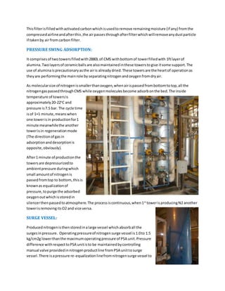
Thisfilterisfilledwithactivatedcarbonwhichisusedtoremove remainingmoisture (if any) fromthe
compressedairlineandafterthis,the airpassesthroughafterfilterwhichwillremoveanydustparticle
if takenby air fromcarbon filter.
PRESSURE SWING ADSORPTION:
It comprisesof twotowersfilledwith2880L of CMS withbottomof towerfilledwith 1ftlayerof
alumina.Twolayersof ceramicballsare alsomaintainedinthese towerstogive itsome support.The
use of aluminaisprecautionaryasthe airis alreadydried.These towersare the heartof operationas
theyare performingthe mainrole by separatingnitrogenandoxygenfromdryair.
As molecularsize of nitrogenissmallerthanoxygen,whenairispassedfrombottomtotop,all the
nitrogengaspassedthroughCMS while oxygenmoleculesbecome adsorbonthe bed.The inside
temperature of towersis
approximately20-22o
C and
pressure is7.5 bar. The cycle time
isof 1+1 minute,meanswhen
one towerisin productionfor1
minute meanwhilethe another
towerisin regenerationmode
(The directionof gasin
adsorptionanddesorptionis
opposite,obviously).
After1 minute of productionthe
towersare depressurizedto
ambientpressure duringwhich
small amountof nitrogenis
passedfromtop to bottom,thisis
knownas equalizationof
pressure,topurge the adsorbed
oxygenoutwhichisstoredin
silencerthenpassedtoatmosphere.The processiscontinuous,when1st
towerisproducingN2 another
towerisremovingitsO2 and vice versa.
SURGE VESSEL:
Producednitrogenisthenstoredinalarge vessel whichabsorball the
surgesinpressure. Operatingpressureof nitrogensurge vessel is1.0to 1.5
kg/cm2g lowerthanthe maximumoperatingpressure of PSA unit.Pressure
difference withrespecttoPSA unitisto be maintainedbycontrolling
manual valve providedinnitrogenproductline fromPSA unittosurge
vessel.There isapressure re-equalizationlinefromnitrogensurge vessel to
PSA unitwithan orifice.Aftereverycycle change over,there isrushof nitrogengasfromsurge vessel to
PSA tower,resultinginfall inpressure by0.2to 0.5 kg/cm2g inthe surge vessel.Fromsurge vessel,raw-
nitrogentothe downstream –DE Oxosystemflow throughflow meteratconstantflow rate andpurity.
Purityof nitrogengas(raw-nitrogen)insurge vesselismaintainedupto99%.
DE-OXO UNIT:
Thisunitis usedtoremove the remaining1% oxygen.Forthisa mixture of hydrogennitrogengasis
introducedinthisvessel.Hydrogenreactwithoxygeninthe presence of palladiumcatalysttoform
water;
O2+2H2 2H2O
Thisis an exothermicreaction.Hence,with1% oxygencontents,the reactiontemperature remainsup
to 220°C (± 10°C). If oxygenpercentage ismore orless,the reactiontemperature will alsoincreaseor
decrease by21°C per0.1 % of oxygen.Double of hydrogenisrequired(byvolume)forremoval of
oxygencontents.Toavoidanyslippage of oxygentrace withoutreaction,hydrogenismaintainedslightly
higher(min.0.5%) or saysup to 2.5 timesof the oxygencontents(intotal).
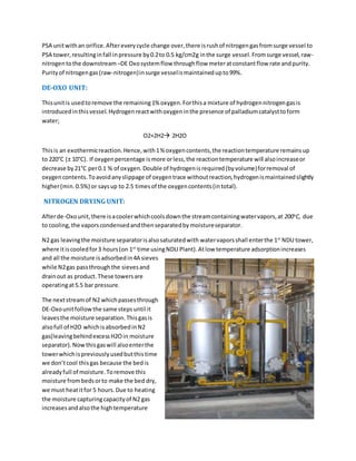
NITROGEN DRYING UNIT:
Afterde-Oxounit,there isacoolerwhichcoolsdownthe streamcontainingwatervapors,at 200o
C, due
to cooling,the vaporscondensedandthenseparatedbymoistureseparator.
N2 gas leavingthe moisture separatorisalsosaturatedwith watervaporsshall enterthe 1st
NDU tower,
where itiscooledfor3 hours(on 1st
time usingNDU Plant).Atlow temperature adsorptionincreases
and all the moisture isadsorbedin4A sieves
while N2gas passthroughthe sievesand
drainout as product.These towersare
operatingat5.5 bar pressure.
The nextstreamof N2 whichpassesthrough
DE-Oxounitfollowthe same stepsuntil it
leavesthe moisture separation.Thisgasis
alsofull of H2O whichisabsorbedinN2
gas(leavingbehindexcessH2Oin moisture
separator).Nowthisgaswill alsoenterthe
towerwhichispreviouslyusedbutthistime
we don’tcool thisgas because the bedis
alreadyfull of moisture.Toremove this
moisture frombedsorto make the bed dry,
we must heatitfor 5 hours.Due to heating
the moisture capturingcapacityof N2 gas
increasesandalsothe hightemperature
increase the rate of desorptionof bed.Hence all the moistureconvertsintovaporsandabsorbinheated
N2 gas whichalreadycontainsome moisture.
Nowthisbedis completelydriedout,capable of adsorbingmore moisture.The heatedgasisthen
passedto coolers.Because of cooling,the watervaporswhichittakesfromthe towerscondensedout
and separatedbymoisture separator.Now the gascontainsthe same amountof moisture aswhenit
comesout from1st
moisture separator.Thisgasthenpassedtothe nextNDU towerwhichisnot yet
used(hence dry).Here gasiscool downfor3 hourscausingall the moisture toadsorbinbedand dry N2
iscollectedasproduct.
The third batchof N2 gas, afterpassingthroughmoisture separator,willenterthe 2nd
towerwhere itis
onlyusedforthe dryingof that towerandthenafterremovingall the moisture of 2nd
tower,itenters
the 1st
tower,whichisdriedoutbypreviousbatch.Here thisgas iscool downto dryN2 gas.The process
continuesanddrynitrogen,
whichcontains0.00% O2, is
collectedindistributiontank.
AMMONIA CRACKER:
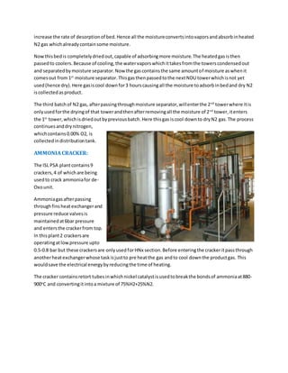
The ISL PSA plantcontains9
crackers,4 of whichare being
usedto crack ammoniafor de-
Oxounit.
Ammoniagasafterpassing
throughfinsheatexchangerand
pressure reduce valvesis
maintainedat6bar pressure
and entersthe crackerfrom top.
In thisplant2 crackersare
operatingatlowpressure upto
0.5-0.8 bar but these crackersare onlyusedforHNx section.Before enteringthe crackeritpassthrough
anotherheatexchangerwhose taskisjustto pre heatthe gas andto cool downthe productgas. This
wouldsave the electrical energybyreducingthe time of heating.
The cracker containsretort tubesinwhichnickel catalystisusedtobreakthe bondsof ammoniaat880-
900o
C and convertingitintoa mixture of 75%H2+25%N2.
Duringcommissioning,initial 24-48hrs. periodiscalled“catalystconversionperiod”.Nickelcatalystis
available inthe formof nickel oxideandgetsconverttonickel duringinitialcommissioning/trial runof
the system.Reactiontakesplace asunder: -
NH3-75% H2 + 25% N2 (CrackedGas)
(Crackedgas) N2+ H2+ NiO Ni + H2O+N2
Afterall the catalystconvertsto nickel,the crackercan be usedfor production.
The product streamcontainsN2+H2+H2O(v).Vapors can be removedbydryingthisstreamin
CDU(crackedgas dryingunit).
CDU:
Thisunitalso
comprisesof 2
towersfilled
withA4 sieves
(A4 sievesare
usedto
separate
moisture).
Pressure of
towersis
maintainedat
6 bars.Before
the gas enters
the towersit
passes
throughfilter
whichshall remove all the dustparticlesfromit. Thenthe gaspassedtotwintowers.The operatingcycle
time of 24 + 24 hrs. Bothtowersare filledwithmolecularsievestoadsorbuncrackedammoniacontents
and dulyfittedwithindividual regenerationheaters.One
towerremainsunderdrying/purifyingoperationfor24 hrs.
Andsubsequentlyothertowerremainsunderregeneration
processfor the same period.After24 hrs.Change overtake
place throughautomaticchange overvalve withPLC.
Duringproductioncycle,the gaspassedthroughthe tower
frombottomto top causingall the uncrackedgas and
moisture toadsorbin the bedleavingasdrygas of nitrogen
hydrogenmixture.While duringregenerationprocess,thisbedisheated
upto150o
C witha small purgingof gas.This will desorbhe bedandall
the uncrackedgas and moisture shall be removedleavingbehindadry
towerwhichisthenreadyfor doingmore moisture separation.The dry
gas isthentransferredtode-Oxounit.
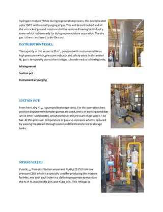
DISTRIBUTION VESSEL:
The capacity of thisvessel is10 m3
, providedwithinstruments like as
highpressure switch,pressure indicatorandsafetyvalve.Inthisvessel
N2 gas istemporallystoredthenthisgasistransferredtofollowingunits;
Mixingvessel
Suction pot
Instrumentair purging
SUCTION POT:
From here,dryN2 gas ispumped tostorage tanks.For thisoperation;two
positive displacementsimplexpumpsare used,one isinworkingcondition
while otherisof standby,whichincreasesthe pressure of gasupto17-18
bar. At thispressure,temperature of gasalsoincreaseswhichis reduced
by passingthe streamthroughcoolerandthentransferredtostorage
tanks.
MIXING VELLEL:
Pure N2 gas fromdistributionvesselandN2+H2 (25:75) fromlow
pressure CDU,whichis especiallyusedforproducingthismixture
for HNx,mix with eachotherina definite proportiontomaintain
the % of H2 at outletbe 25% and N2 be 75%. This HNx gas is
suppliedtoGP(galvanizingplant) whereitisusedtocontrol the amount of oxidesonthe sheet.
INSTRUMENT AIR PURGING:
At manyplaceswithinthe industrynitrogengasisusedforoperatingdifferentinstrumentsforexample
valves,pressure switches,pneumaticinstrumentsetc.thisnitrogengasisusedatthese places.
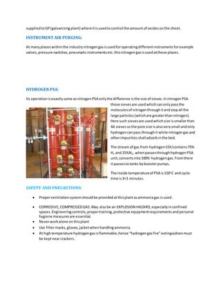
HYDROGEN PSA:
Its operationisexactlysame asnitrogenPSA onlythe difference isthe size of sieves.InnitrogenPSA
those sievesare usedwhichcanonlypassthe
moleculesof nitrogenthroughitandstopall the
large particles(whichare greaterthannitrogen).
Here such sievesare usedwhichsize issmallerthan
4A sievesso the pore size isalsoverysmall andonly
hydrogencanpass throughit while nitrogengasand
otherimpuritiesshalladsorbinthe bed.
The stream of gas from hydrogenCDUcontains75%
H2 and 25%N2, whenpassesthroughhydrogenPSA
unit,convertsinto100% hydrogengas.Fromthere
it passestotanks byboosterpumps.
The inside temperatureof PSA is150o
C and cycle
time is3+3 minutes.
SAFETY AND PRECAUTIONS:
 Properventilationsystemshouldbe providedatthisplantasammoniagas isused.
 CORROSIVE,COMPRESSEDGAS.May alsobe an EXPLOSION HAZARD,especiallyinconfined
spaces.Engineeringcontrols,propertraining,protective equipmentrequirementsandpersonal
hygiene measuresare essential.
 Neverworkalone onthisplant
 Use filtermasks,gloves,jacketwhenhandlingammonia.
 At hightemperature hydrogengasisflammable,hence “hydrogengasfire”extinguishersmust
be keptnear crackers.

More Related Content

What's hot

internship report final.DOC
internship report final.DOCinternship report final.DOC
internship report final.DOCqazi faisal
 
Reverse rotaion of co2 compressor
Reverse rotaion of co2 compressorReverse rotaion of co2 compressor
Reverse rotaion of co2 compressorPrem Baboo
 
Distillation dehydration (sieves)5
Distillation dehydration (sieves)5Distillation dehydration (sieves)5
Distillation dehydration (sieves)5Cara Mullen
 
Distillation basic training
Distillation basic trainingDistillation basic training
Distillation basic trainingCara Mullen
 
Compressor fundamentals
Compressor fundamentalsCompressor fundamentals
Compressor fundamentalsPrem Baboo
 
C3.2.2. Topside Gas Compression_2020
 C3.2.2. Topside Gas Compression_2020 C3.2.2. Topside Gas Compression_2020
C3.2.2. Topside Gas Compression_2020David Seow
 
project_presentation-Original - wht_theme
project_presentation-Original - wht_themeproject_presentation-Original - wht_theme
project_presentation-Original - wht_themeShaheem TM
 
C3.1.0. Topside Intro 2020
C3.1.0. Topside Intro 2020C3.1.0. Topside Intro 2020
C3.1.0. Topside Intro 2020David Seow
 
DelayedCokingPoster-022608LR
DelayedCokingPoster-022608LRDelayedCokingPoster-022608LR
DelayedCokingPoster-022608LRChris Jones
 
103671766 a-students-guide-to-refinery
103671766 a-students-guide-to-refinery103671766 a-students-guide-to-refinery
103671766 a-students-guide-to-refineryvijaykale1981
 
4 b = 58 p 45 basic ur plant description 06.09.2021-1
4 b = 58 p  45 basic ur plant description 06.09.2021-14 b = 58 p  45 basic ur plant description 06.09.2021-1
4 b = 58 p 45 basic ur plant description 06.09.2021-1ameermudasar
 
C3.2.1. Topside Separation_2020
C3.2.1. Topside Separation_2020C3.2.1. Topside Separation_2020
C3.2.1. Topside Separation_2020David Seow
 
Ig system & equipment oil tankers
Ig system &  equipment oil tankersIg system &  equipment oil tankers
Ig system & equipment oil tankersjabbar2002pk200
 
Environment management and advanced waste treatment system in nitrogenious fe...
Environment management and advanced waste treatment system in nitrogenious fe...Environment management and advanced waste treatment system in nitrogenious fe...
Environment management and advanced waste treatment system in nitrogenious fe...Prem Baboo
 
THERMAL POWER PLANT OPERATIONS
THERMAL POWER PLANT OPERATIONSTHERMAL POWER PLANT OPERATIONS
THERMAL POWER PLANT OPERATIONSManohar Tatwawadi
 
C3.2.3&4. Fluid Recovery _2020
C3.2.3&4. Fluid Recovery _2020C3.2.3&4. Fluid Recovery _2020
C3.2.3&4. Fluid Recovery _2020David Seow
 

What's hot (20)

internship report final.DOC
internship report final.DOCinternship report final.DOC
internship report final.DOC
 
Reverse rotaion of co2 compressor
Reverse rotaion of co2 compressorReverse rotaion of co2 compressor
Reverse rotaion of co2 compressor
 
Distillation
DistillationDistillation
Distillation
 
Distillation dehydration (sieves)5
Distillation dehydration (sieves)5Distillation dehydration (sieves)5
Distillation dehydration (sieves)5
 
Distillation basic training
Distillation basic trainingDistillation basic training
Distillation basic training
 
Compressor fundamentals
Compressor fundamentalsCompressor fundamentals
Compressor fundamentals
 
C3.2.2. Topside Gas Compression_2020
 C3.2.2. Topside Gas Compression_2020 C3.2.2. Topside Gas Compression_2020
C3.2.2. Topside Gas Compression_2020
 
Fuel Oil Systems
Fuel Oil SystemsFuel Oil Systems
Fuel Oil Systems
 
project_presentation-Original - wht_theme
project_presentation-Original - wht_themeproject_presentation-Original - wht_theme
project_presentation-Original - wht_theme
 
Oil Refining
Oil RefiningOil Refining
Oil Refining
 
C3.1.0. Topside Intro 2020
C3.1.0. Topside Intro 2020C3.1.0. Topside Intro 2020
C3.1.0. Topside Intro 2020
 
DelayedCokingPoster-022608LR
DelayedCokingPoster-022608LRDelayedCokingPoster-022608LR
DelayedCokingPoster-022608LR
 
103671766 a-students-guide-to-refinery
103671766 a-students-guide-to-refinery103671766 a-students-guide-to-refinery
103671766 a-students-guide-to-refinery
 
4 b = 58 p 45 basic ur plant description 06.09.2021-1
4 b = 58 p  45 basic ur plant description 06.09.2021-14 b = 58 p  45 basic ur plant description 06.09.2021-1
4 b = 58 p 45 basic ur plant description 06.09.2021-1
 
C3.2.1. Topside Separation_2020
C3.2.1. Topside Separation_2020C3.2.1. Topside Separation_2020
C3.2.1. Topside Separation_2020
 
Ig system & equipment oil tankers
Ig system &  equipment oil tankersIg system &  equipment oil tankers
Ig system & equipment oil tankers
 
Environment management and advanced waste treatment system in nitrogenious fe...
Environment management and advanced waste treatment system in nitrogenious fe...Environment management and advanced waste treatment system in nitrogenious fe...
Environment management and advanced waste treatment system in nitrogenious fe...
 
THERMAL POWER PLANT OPERATIONS
THERMAL POWER PLANT OPERATIONSTHERMAL POWER PLANT OPERATIONS
THERMAL POWER PLANT OPERATIONS
 
C3.2.3&4. Fluid Recovery _2020
C3.2.3&4. Fluid Recovery _2020C3.2.3&4. Fluid Recovery _2020
C3.2.3&4. Fluid Recovery _2020
 
FINAL REPORT PPT
FINAL REPORT PPTFINAL REPORT PPT
FINAL REPORT PPT
 

Viewers also liked

Herramientas web-2.0-mariana
Herramientas web-2.0-marianaHerramientas web-2.0-mariana
Herramientas web-2.0-marianajuanchocool
 
らいとにんぐとーく
らいとにんぐとーくらいとにんぐとーく
らいとにんぐとーくIsao Aruga
 
Sueño mi universidad cultura ciudadana
Sueño mi universidad cultura ciudadana Sueño mi universidad cultura ciudadana
Sueño mi universidad cultura ciudadana laura Reales
 
Journal Publication - Tom Parsons and Alan Bairner
Journal Publication - Tom Parsons and Alan BairnerJournal Publication - Tom Parsons and Alan Bairner
Journal Publication - Tom Parsons and Alan BairnerTom Parsons
 

Viewers also liked (7)

Business intelligence
Business intelligenceBusiness intelligence
Business intelligence
 
Aussie wire
Aussie wireAussie wire
Aussie wire
 
Herramientas web-2.0-mariana
Herramientas web-2.0-marianaHerramientas web-2.0-mariana
Herramientas web-2.0-mariana
 
らいとにんぐとーく
らいとにんぐとーくらいとにんぐとーく
らいとにんぐとーく
 
WV CV_Eng_2016
WV CV_Eng_2016WV CV_Eng_2016
WV CV_Eng_2016
 
Sueño mi universidad cultura ciudadana
Sueño mi universidad cultura ciudadana Sueño mi universidad cultura ciudadana
Sueño mi universidad cultura ciudadana
 
Journal Publication - Tom Parsons and Alan Bairner
Journal Publication - Tom Parsons and Alan BairnerJournal Publication - Tom Parsons and Alan Bairner
Journal Publication - Tom Parsons and Alan Bairner
 

Similar to internship report

ITTEHAD CHEMICAL INTERNSHIP REPORT
  ITTEHAD CHEMICAL INTERNSHIP REPORT   ITTEHAD CHEMICAL INTERNSHIP REPORT
ITTEHAD CHEMICAL INTERNSHIP REPORT Malik Hamid
 
Boiler Drum And Its Internals
Boiler Drum And Its InternalsBoiler Drum And Its Internals
Boiler Drum And Its InternalsAshrant Dass
 
HIGH PRESUURE LEACH PLANT PRESENTATION - W KAUZI
HIGH PRESUURE LEACH PLANT PRESENTATION - W KAUZIHIGH PRESUURE LEACH PLANT PRESENTATION - W KAUZI
HIGH PRESUURE LEACH PLANT PRESENTATION - W KAUZIwina kauzi
 
standard units | multi purpose unit | falling film absorber
standard units | multi purpose unit | falling film absorberstandard units | multi purpose unit | falling film absorber
standard units | multi purpose unit | falling film absorberGoel Scientific
 
DISTILLED WATER - PREPARATION, GRADES, RISKS, STORAGE, PURITY, DETECTION OF I...
DISTILLED WATER - PREPARATION, GRADES, RISKS, STORAGE, PURITY, DETECTION OF I...DISTILLED WATER - PREPARATION, GRADES, RISKS, STORAGE, PURITY, DETECTION OF I...
DISTILLED WATER - PREPARATION, GRADES, RISKS, STORAGE, PURITY, DETECTION OF I...ASWIN ANANDH
 
INDUCTION AT INDUSTRIAL SERVICE OF .pptx
INDUCTION AT INDUSTRIAL SERVICE OF .pptxINDUCTION AT INDUSTRIAL SERVICE OF .pptx
INDUCTION AT INDUSTRIAL SERVICE OF .pptxEmmanuelIsiayinekife
 
mech 2nd yr lab report.pdf
mech 2nd yr lab report.pdfmech 2nd yr lab report.pdf
mech 2nd yr lab report.pdfMOHDAHMED52
 
technical-packages.pdf |Goel scientific | Canada
technical-packages.pdf |Goel scientific | Canadatechnical-packages.pdf |Goel scientific | Canada
technical-packages.pdf |Goel scientific | CanadaGoelScientific1
 
Dry Pellet Chlorinator In-Line Chlorinator Model 400 Installation Guide
 Dry Pellet Chlorinator In-Line Chlorinator Model 400 Installation Guide Dry Pellet Chlorinator In-Line Chlorinator Model 400 Installation Guide
Dry Pellet Chlorinator In-Line Chlorinator Model 400 Installation GuideClean Water Systems
 
Mass transfer (practical) Assignment
Mass transfer (practical) AssignmentMass transfer (practical) Assignment
Mass transfer (practical) AssignmentMehtab Rai
 
BOILER MOUNTING AND ACCESSORIES
BOILER MOUNTING AND ACCESSORIES BOILER MOUNTING AND ACCESSORIES
BOILER MOUNTING AND ACCESSORIES AnkitBihola
 
PRESENTATION ON INPLANT TRAINING AT MRPL
PRESENTATION ON INPLANT TRAINING AT MRPLPRESENTATION ON INPLANT TRAINING AT MRPL
PRESENTATION ON INPLANT TRAINING AT MRPLAnkit Devatwal
 
Oil & Gas Production
Oil & Gas ProductionOil & Gas Production
Oil & Gas ProductionTarek Saati
 
BOILER MOUNTINGS & ACCESSORIES
BOILER MOUNTINGS & ACCESSORIESBOILER MOUNTINGS & ACCESSORIES
BOILER MOUNTINGS & ACCESSORIESSmit Shah
 
Sunil- Thermal Power Plant
Sunil- Thermal Power PlantSunil- Thermal Power Plant
Sunil- Thermal Power PlantSunil8889
 

Similar to internship report (20)

ITTEHAD CHEMICAL INTERNSHIP REPORT
  ITTEHAD CHEMICAL INTERNSHIP REPORT   ITTEHAD CHEMICAL INTERNSHIP REPORT
ITTEHAD CHEMICAL INTERNSHIP REPORT
 
Boiler Drum And Its Internals
Boiler Drum And Its InternalsBoiler Drum And Its Internals
Boiler Drum And Its Internals
 
Boiler
Boiler Boiler
Boiler
 
HIGH PRESUURE LEACH PLANT PRESENTATION - W KAUZI
HIGH PRESUURE LEACH PLANT PRESENTATION - W KAUZIHIGH PRESUURE LEACH PLANT PRESENTATION - W KAUZI
HIGH PRESUURE LEACH PLANT PRESENTATION - W KAUZI
 
Soda Ash.docx
Soda Ash.docxSoda Ash.docx
Soda Ash.docx
 
standard units | multi purpose unit | falling film absorber
standard units | multi purpose unit | falling film absorberstandard units | multi purpose unit | falling film absorber
standard units | multi purpose unit | falling film absorber
 
DISTILLED WATER - PREPARATION, GRADES, RISKS, STORAGE, PURITY, DETECTION OF I...
DISTILLED WATER - PREPARATION, GRADES, RISKS, STORAGE, PURITY, DETECTION OF I...DISTILLED WATER - PREPARATION, GRADES, RISKS, STORAGE, PURITY, DETECTION OF I...
DISTILLED WATER - PREPARATION, GRADES, RISKS, STORAGE, PURITY, DETECTION OF I...
 
INDUCTION AT INDUSTRIAL SERVICE OF .pptx
INDUCTION AT INDUSTRIAL SERVICE OF .pptxINDUCTION AT INDUSTRIAL SERVICE OF .pptx
INDUCTION AT INDUSTRIAL SERVICE OF .pptx
 
mech 2nd yr lab report.pdf
mech 2nd yr lab report.pdfmech 2nd yr lab report.pdf
mech 2nd yr lab report.pdf
 
technical-packages.pdf |Goel scientific | Canada
technical-packages.pdf |Goel scientific | Canadatechnical-packages.pdf |Goel scientific | Canada
technical-packages.pdf |Goel scientific | Canada
 
Dry Pellet Chlorinator In-Line Chlorinator Model 400 Installation Guide
 Dry Pellet Chlorinator In-Line Chlorinator Model 400 Installation Guide Dry Pellet Chlorinator In-Line Chlorinator Model 400 Installation Guide
Dry Pellet Chlorinator In-Line Chlorinator Model 400 Installation Guide
 
SaadJutt
SaadJuttSaadJutt
SaadJutt
 
Mass transfer (practical) Assignment
Mass transfer (practical) AssignmentMass transfer (practical) Assignment
Mass transfer (practical) Assignment
 
BOILER MOUNTING AND ACCESSORIES
BOILER MOUNTING AND ACCESSORIES BOILER MOUNTING AND ACCESSORIES
BOILER MOUNTING AND ACCESSORIES
 
PRESENTATION ON INPLANT TRAINING AT MRPL
PRESENTATION ON INPLANT TRAINING AT MRPLPRESENTATION ON INPLANT TRAINING AT MRPL
PRESENTATION ON INPLANT TRAINING AT MRPL
 
Oil & Gas Production
Oil & Gas ProductionOil & Gas Production
Oil & Gas Production
 
BOILER MOUNTINGS & ACCESSORIES
BOILER MOUNTINGS & ACCESSORIESBOILER MOUNTINGS & ACCESSORIES
BOILER MOUNTINGS & ACCESSORIES
 
Sunil- Thermal Power Plant
Sunil- Thermal Power PlantSunil- Thermal Power Plant
Sunil- Thermal Power Plant
 
INTERN
INTERNINTERN
INTERN
 
sugar mill ss.pptx
sugar mill ss.pptxsugar mill ss.pptx
sugar mill ss.pptx
 

internship report

  • 1. ACID REGENERATION PLANT MAIN PROCESS The main objective of this plant is to regenerate the spent acid which is coming from pickling .At pickling the acid is showered at moving sheets of rusted steel due to which high amount of iron chloride become mixed with this acid. Our plant is not only regenerating the acid upto 99% but also formed a valuable by- product, i.e. Fe2O3.The flow diagram of the process is MAIN FEATURES: Thisis Pakistan’sonlyacidregenerationplantforuse insteel workspickling,hasprovidedconsiderably processingadvantages,including:  .Extremelylowemissionvalue.  .The ironoxide by-producthasa highmarketvalue  .Recoveryrate of HCl ishigherthan99%.  .Constantacidqualityandcompositionensure uniformandhighqualitypickling.  .Rinse waterinthe pickling line isusedinacidregenerationprocess,thusconsiderablyreducing waste waterproduction.  .The keydesignfeature of achievingextremelylow levelsof waste gasanddustemissionwhich are belowcurrentlegislationlimits.  .Adjustable acidconcentrationof regeneratedacid.  .Independentfromchemical suppliers.  .Automatedcontrol system. FUEL: Natural gas Minimum calorific value 7400kcal/Nm3 Pressure 25 kPa. CO2 2.485% CH4 88.789% N2 3.853%
  • 2. RINSE WATER INDUSTRIAL WATER COMPRESSED AIR Pressure 150kPa. Pressure 300kPa. Pressure 500kPa. Temperature 60C Temperature 35C Dew point 10C Fe 5g/l Hardness 200 ppm CaCO3 below minimum HCl 15g/l Ph 7-8.2 ambient temp. NITROGEN WASTE WATER REGENERATED ACID Pressure 500-700kPa. Amount 250l/hr Amount 2000l/hr Temperature ambient Cl- 25g/l Total HCl con. 25g/l Purity 99.9% Fe++/+++ 15g/l Fe. 5g/l MECHANICAL EQUIPMENTS USED AT ARP: Spray roaster 1 spray unit 1 lump breaker Rotary valve Burner equipments 2 burners 2 uv-flame detector 1 combustion air blower I set of burner piping Dust separator Cyclone separator 1 rotary valve Pre concentrator with separator Venturi Separator Absorption column Exhaust fan Gas cleaning system Scrubber Horizontal drop separator Vertical drop separator 1 fume stack Collecting bin
  • 3. Oxide station 1 oxide bin Gate valve 1 rotary valve 1 oxide separation filter Oxide conveying pipes Steel pipes Conveying air fan 1 big bag fillng device Storage tanks and pumps for ARP 1 tank for waste pickle liquor 1 tank for regenerated acid 1 tank for rinse water 1 tank for fresh acid 2 pumps for waste pickle liquor 2 pumps for regenerated acid 2 pumps for rinse water 1 pump for fresh acid 2 pumps for the sump pit 2 pumps for pre-concentrator 2 pumps for reactor feeding 2 pumps for absorber 2 pumps for gas scrubber 1 booster station. 2 pumps for water Filters 1 filter for waste pickle liquor 2 filters for roaster charge
  • 4. PROCESS DESCRIPTION: OPERATION MODE: ARPconsistof 4 modes  No mode  Freshwatermode  Rinse watermode  Waste water mode START UP PROCEDURE: The veryfirstthingwe have to do is to checkof leakage.Aftersatisfaction,we shall startthe suction pumpwhichislocatedbelowthe roaster;the objective of startingthisfanistosuck all the unwanted gaseswhichare presentinroaster,thenthe rotarypumpof lumpbreakeristurnon followedbythe turningon of rotary pumpof venturi whichisinterlockedwiththe previouspump. Thenopenthe industrial waterpump thenopenpreconcentratorpumpthenturnonthe circulationof absorber,thiscause the removal of interlockonexhaustfan,simplyturniton thenstart the circulation of scrubber. Adjustthe gasflowrate to the burners.Butonly1 burnershouldbe onbecause thisisthe freshmode. Aftersome hoursthe plantwouldbe tune to rinse watermode inwhich2nd burnerwill alsobe started and rinse waterpumpison withturningoff of ind.Waterpump.As soonthe temperature,inside the roaster,reachedat 600oC, andthe topof the roasterreached400oC, insert1st nozzle andstart spraying the water.By doingthisthe temperature of the topside decreasedtocertainvalue butwill soonstart increasing.Whentemperature of topof the roasterreacheditsset value again, insertanothernozzle and run the plantfor several hoursonrinse mode. Whenthe plantis switchedtowaste acidmode,we justhave to switchthe inletof separatorfromrinse to waste acidline bysimplyopeningandclosingof waste acidand rinse waterpumprespectively. WHAT IS ACTUALLY HAPPENING IN ARP?? In thisprocessthe spentacidis sprayatomizedintoadirectlyfiredfurnace and(bycontactwithoxygen) and splittedintoFe2O3powder(solidphase)andHCl (gasphase).Reactiontemperaturesare inarange of 400 to 700 degC. The gaseousHCl is absorbedinwaterto formregeneratedhydrochloricacidof about17% strengthwhichcan be reusedforpickling.Itiscommonand attractive touse the slightly acidicrinse waterfromthe picklinglineasabsorptionliquids. The three basic processstepsof thisprocessare preconcentration,roastingandabsorption.Inthe preconcentrationphase,the incomingwaste acidundergoesdirectheatandmassexchange withthe
  • 5. hot exhaustgasfromthe roaster furnace.The directheatexchange isaccomplishedinaventuri evaporatorwhere the waste acidisatomizedandturbulentlyintermixedwiththe roastgasat high velocities.The waste gasisthuspartiallyevaporated,leavingbehindapreconcentrated waste acidtobe usedas liquidfeedtothe sprayroastingfurnace. Inventuri 25% by volume of acidisevaporatedanditis cooledfrom950c TO 400c and itis dedusted. In the spray furnace,the preconcentratedwasteacidwhichisinjectedfromthe topbymeansof high pressure atomizingnozzlesundergoesadropby dropevaporationof waterandHCl as well aspyro hydrolysisreactionof remainingironchloridesandexcessoxygenprovidedbythe burners,whichare tangentiallyalignedaroundthe furnace circumference inordertoforma specific‘swirl’flow pattern whichincreasesthe dropletretentiontime byincreasingthe length of itspaththroughthe furnace.The chemical reactionproductsof the pyrohydrolysisreactionconsistof HCl whichisextractedfromthe top of the furnace togetherwiththe steamand combustionproductsand ferricoxide (Fe2O3) powderwhich settlesatthe conical bottomof the furnace ispneumaticallyconveyed intoa storage bin forsuitable disposal.The pyrohydrolysis reactionsare as follows: 12FeCl2+3O2=8FeCl3+2Fe2O3 2FeCl3+3H2O=6HCl+Fe2O3
  • 6. Afterthe streamof gassesescape the topof the furnace theyallowedtopassthroughthe cyclone separator.Incyclone separatorit entersatan angle due to whicha cyclone isformedinit,whichcauses veryhighvelocityatthe axisof cyclone and very lowvelocityatthe side wallsof it,due towhichif some particlesof ironoxide come alongwiththe gas will move towardsthe wallsof separatorbythe influenceof centrifugalforce andthusall the particleswill leave the bottomof cyclone andshall discharge againinthe roaster. The dust free hotgas iswhenpassedthroughthe cyclone itentersthe venturi where heattransfer, mass transferandevaporationoccurs,whichis alreadydescribedabove. Thenthe gas is passedtoabsorber. In thisabsorber,physical absorptionistakingplace.Thisnon-reactiveabsorptionismade betweenthe twophasesi.e.the gas phase (fromthe topof separator) andthe liquidphase (dilute acid).Whenthese twophasescome in contact witheachother,masstransfer occurs at interphase atthe rate dependinguponthe flow ratesof bothgas and liquid.Thistype of absorptiondepends uponthe solubilityof gasin liquid, temperatureand pressure.Thoughthe pressure isverylow butthiseffectcan be balancedbyincreasingthe flow rate of liquiduptocertain limit. The absorptionalsodependsuponthe contacttime between liquidingas,inthiscase betweendiluteacid andHCl gas fumes.Forthiswe are usingstructuredpackinginside the absorber. The acid whichcomesfromthe bottomof the absorberis thencollectedin“regeneratedacidtank”. Afterabsorptioncolumn,there isanexhaustfanwhichis responsible forthe suctionof roastedgasby creating
  • 7. negative pressure.Asthe acidicgasis flowingthroughthe fan,we have toshowerwater atfast moving impellersforsavingitfromcorrosion. Gas is nowalmostfree of chlorine gas.The restof the chlorine ingasis thenremovedbypassingit throughthe scrubberin whichall the chlorine isconvertedtoHCl andthe gas leavingthroughthe stack to the atmosphere have concentrationof chlorineupto0.00%. OTHER EQUIPMENTS USEDAT ARP FLAP VALVE: Designed for use on the discharge end of pipes to prevent backflow or intrusion into the pipe. Typical applications include discharges to reservoirs, ponding basins and standpipes. BALL VALVE: A ball valve is a valve with a spherical disc, the part of the valve which controls the flow through it. The sphere has a hole, or port, through the middle so that when the port is in line with both ends of the valve, flow will occur. When the valve is closed, the hole is perpendicular to the ends of the valve, and flow is blocked. The handle or lever will be in line with the port position letting you "see" the valve's position. The ball valve, along with the butterfly valve and plug valve, are part of the family of quarter turn valves.
  • 8. SOLENOID VALVE: A solenoid valve is an electromechanically operated valve. The valve is controlled by an electric current through a solenoid: in the case of a two-port valve the flow is switched on or off; in the case of a three-port valve, the outflow is switched between the two outlet ports. Multiple solenoid valves can be placed together on a manifold. Solenoid valves are the most frequently used control elements in fluidics. Their tasks are to shut off, release, dose, distribute or mix fluids. They are found in many application areas. Solenoids offer fast and safe switching, high reliability, long service life, good medium compatibility of the materials used, low control power and compact design. DIAPHRAGM VALVE: Diaphragm valves can be manual or automated. Their application is generally as shut-off valves in process systems within the industrial, food and beverage, pharmaceutical and biotech industries. The older generation of these valves is not suited for regulating and controlling process flows, however newer developments in this area have successfully tackled this problem.
  • 9. MATERIAL OF PIPING AND VALVES Valvesare made up of Niobiumwhich meltingpointis 2477oC, hence it isnot sensitiveto heat. Almostall the pipingismade up of PP(Polypropylene) ratherthanPVC(Polyvinyl chloride),because PP’smeltingpointishigherthan PVCand itis alsoa neutral polymer. If it is exposedtofire,itsimplyconvertedintocarbondioxide andwaterwhile PVCshall formoxinsand HCl gas whichare toxicto environment. SAFETYANDMAINTAINANCE GENEREL MAINTAINANACE:  Cleanregularlyall workingareasexposedtooxide dustatleastevery2 days  All the designedparameters(temperature,pressure,flow ratesetc.) of eachandevery equipmentmustbe controlled withspecial care.  Make sure and ironoxide formedmustbe inthe formof amorphousform, otherwise itwill cause chockingeffect.  Safetyshowers,eye rinsebottlesandfirstaidmaterial are tobe providedatappropriate places inthe plant.  Noise levelinthe workingareaswill notexceed85dBs.Anyequipmentproducinganoise level higherthan85dBs (e.g.pumpsandfans) shouldbe installedinasecondprotectedroom.This room isnot to be consideredinworkingareas.  Industrial waterlining,whichisusedforcleaningpurposes,shouldbe of PVC(notof mildsteel). PERSONAL SAFETY:  Wear personal protectionequipmentnearchemicals.  Avoidinhalingoxide dust.  Close inspectioncoversordoorsduringoperation.
  • 10. PSA PLANT The PSA plantof ISL is producingpure N2and H2 gas and a mixture of them, whichisusedindifferent processes. Compressedairisusedasa raw material fornitrogenproductionasitcontains79% of it while ammonia gas iscracked to produce hydrogengas. DESIGN & OPERATING DATA PRODUCTION GAS SPECIFICATION: NITROGEN GASPLANT: (a)Capacity: 300 NM3/hr. (b)Composition… O2: 5 PPM H2: 0.5 % (Max.) N2: Balance (c)DewPoint: (-) 60ºC (d)Op.Temperature: Ambient (e) OutLet Pressure : 5.5 Kg/Cm2g (Before Booster) (f) Out LetPressure : 17.0 kg/cm2g (afterBooster) HIGH PRESSURE AMMONIA CRACKER(1W+1S): (a)Capacity: 12 NM3/HR (b) ProductGas Pressure. : 6.0 Kg/cm2g (c)ProductGas composition: Hydrogen – 75 % Nitrogen–25 % HIGH PRESSURE CRACKEDGAS PURIFICATION SYSTEM
  • 11. (a)Capacity: 12 Nm/Hr. (b)Hydrogen: 75 % (c)Nitrogen: 25 % (d) DewPoint : (-) 60 °C (e) Res.NH3: Nil (e) Pressure atBatteryLimit: 6.0 Kg/cm2g LOW PRESSURE AMMONIA CRACKER(1W+1S) (a)Capacity: 60 NM3/hr. (b) ProductGas Pressure. : 0.2 Kg/cm2g (c)ProductGas composition: Hydrogen – 75 % Nitrogen– 25 % LOW PRESSURE CRACKEDGAS PURIFICATION SYSTEM – 2 Nos. (a)Capacity: 60 Nm/Hr. (b)Hydrogen: 75 % (c)Nitrogen: 25 % (d) DewPoint : (-) 70 °C (e) Res.NH3: Nil (e) Pressure atBatteryLimit: 0.2 Kg/cm2g UTILITIES CONSUMPTION: i) CoolingWater:(ForNitrogenGasPlant& AmmoniaCracker) Flow: (16-18) NM3/Hr. Pressure: 2.5 Kg/cm2 Temperature: 32°C
  • 12. ii) ChilledWater:(ForNitrogenGasPlant) Flow: (2 – 3) NM3/Hr. Pressure: 2.5 kg/cm2g Temperature: (5 – 10) °C iii) CompressedAir:(ForNitrogenGasPlant) Flow: 706 CFM Pressure: (7.0 – 7.5) Kg/Cm2 Temperature: 20°C. iv) AmmoniaGas(For Each 12 NM3/Hr. AmmoniaCracker): FlowfromNH3 Tank : 5 Kgs./Hr. Pressure atinlet(AfterPRV) 6.5 Kg/Cm2 Temperature : Ambient v) AmmoniaGas(For Each 60 NM3/Hr. AmmoniaCracker): FlowfromNH3 Tank : 24 Kgs./Hr. Pressure atinlet(AfterPRV): 0.8 Kg/Cm2 Temperature : Ambient
  • 13. DESCRIPTIONOF PROCESSES Nitrogen production AIR RECEIVER: As itis discussedabove thatnitrogenisseparatedfromair,forthisair is compressedto7.5 bars whichis receivedbyairreceiver,alsocalledasairbuffer.Asthe compressedair, movingwithhighvelocitybythe influence of highpressure difference,entersthe receiver,the static pressure increasesand,itsvelocitydecreases.Hence the excessmoisture condensedtothe bottomof receiverwhichisremovedbyautodrainedvalve.The compressedairfree fromphysical moisture particlesmovesupwardandflowstofilters.Itisadvisabletocheckthroughmanual drainvalve,once in 3-4 hoursfor anywater accumulationinthe airreceiver. Airreceiverisprovidedwithinstrumentslike low pressure switch,pressure indicator,safetyreliefvalve and digital temperature indicatorwithsetpoint. PRE-FILTER: The compressedairthenentersa pre filterwhich containssinteredbronze of 10 micronspore size.Inthis filterlotsof moisture iscondensedbecause of slight increase instaticpressure anddecrease invelocity.Auto and manual drainvalve are providedatthe bottomof thisfilter.Autodrainvalve openforafixedtime periodat regularintervalstodrainthe condensate. FINE-FILTER: In thisfilterborosilicate filterelementisusedof 2 microns pore size.Thisfilterisusedtoremove oil andwaterdropletsfrom airline.Asmoisture sizerangesfrom2-5micrones,itcaneasilybe separatedbythisfilter.The condensatesmustbe drainedout fromthe bottomof the filter.The air,whichpassedthroughfine filter,isnowalmostfree fromanykindof moisture.Thisairis thenpassedtothe carbon filter. ACTIVATED CARBON FILTER AND AFTER FILTER:
  • 14. Thisfilterisfilledwithactivatedcarbonwhichisusedtoremove remainingmoisture (if any) fromthe compressedairlineandafterthis,the airpassesthroughafterfilterwhichwillremoveanydustparticle if takenby air fromcarbon filter. PRESSURE SWING ADSORPTION: It comprisesof twotowersfilledwith2880L of CMS withbottomof towerfilledwith 1ftlayerof alumina.Twolayersof ceramicballsare alsomaintainedinthese towerstogive itsome support.The use of aluminaisprecautionaryasthe airis alreadydried.These towersare the heartof operationas theyare performingthe mainrole by separatingnitrogenandoxygenfromdryair. As molecularsize of nitrogenissmallerthanoxygen,whenairispassedfrombottomtotop,all the nitrogengaspassedthroughCMS while oxygenmoleculesbecome adsorbonthe bed.The inside temperature of towersis approximately20-22o C and pressure is7.5 bar. The cycle time isof 1+1 minute,meanswhen one towerisin productionfor1 minute meanwhilethe another towerisin regenerationmode (The directionof gasin adsorptionanddesorptionis opposite,obviously). After1 minute of productionthe towersare depressurizedto ambientpressure duringwhich small amountof nitrogenis passedfromtop to bottom,thisis knownas equalizationof pressure,topurge the adsorbed oxygenoutwhichisstoredin silencerthenpassedtoatmosphere.The processiscontinuous,when1st towerisproducingN2 another towerisremovingitsO2 and vice versa. SURGE VESSEL: Producednitrogenisthenstoredinalarge vessel whichabsorball the surgesinpressure. Operatingpressureof nitrogensurge vessel is1.0to 1.5 kg/cm2g lowerthanthe maximumoperatingpressure of PSA unit.Pressure difference withrespecttoPSA unitisto be maintainedbycontrolling manual valve providedinnitrogenproductline fromPSA unittosurge vessel.There isapressure re-equalizationlinefromnitrogensurge vessel to
  • 15. PSA unitwithan orifice.Aftereverycycle change over,there isrushof nitrogengasfromsurge vessel to PSA tower,resultinginfall inpressure by0.2to 0.5 kg/cm2g inthe surge vessel.Fromsurge vessel,raw- nitrogentothe downstream –DE Oxosystemflow throughflow meteratconstantflow rate andpurity. Purityof nitrogengas(raw-nitrogen)insurge vesselismaintainedupto99%. DE-OXO UNIT: Thisunitis usedtoremove the remaining1% oxygen.Forthisa mixture of hydrogennitrogengasis introducedinthisvessel.Hydrogenreactwithoxygeninthe presence of palladiumcatalysttoform water; O2+2H2 2H2O Thisis an exothermicreaction.Hence,with1% oxygencontents,the reactiontemperature remainsup to 220°C (± 10°C). If oxygenpercentage ismore orless,the reactiontemperature will alsoincreaseor decrease by21°C per0.1 % of oxygen.Double of hydrogenisrequired(byvolume)forremoval of oxygencontents.Toavoidanyslippage of oxygentrace withoutreaction,hydrogenismaintainedslightly higher(min.0.5%) or saysup to 2.5 timesof the oxygencontents(intotal). NITROGEN DRYING UNIT: Afterde-Oxounit,there isacoolerwhichcoolsdownthe streamcontainingwatervapors,at 200o C, due to cooling,the vaporscondensedandthenseparatedbymoistureseparator. N2 gas leavingthe moisture separatorisalsosaturatedwith watervaporsshall enterthe 1st NDU tower, where itiscooledfor3 hours(on 1st time usingNDU Plant).Atlow temperature adsorptionincreases and all the moisture isadsorbedin4A sieves while N2gas passthroughthe sievesand drainout as product.These towersare operatingat5.5 bar pressure. The nextstreamof N2 whichpassesthrough DE-Oxounitfollowthe same stepsuntil it leavesthe moisture separation.Thisgasis alsofull of H2O whichisabsorbedinN2 gas(leavingbehindexcessH2Oin moisture separator).Nowthisgaswill alsoenterthe towerwhichispreviouslyusedbutthistime we don’tcool thisgas because the bedis alreadyfull of moisture.Toremove this moisture frombedsorto make the bed dry, we must heatitfor 5 hours.Due to heating the moisture capturingcapacityof N2 gas increasesandalsothe hightemperature
  • 16. increase the rate of desorptionof bed.Hence all the moistureconvertsintovaporsandabsorbinheated N2 gas whichalreadycontainsome moisture. Nowthisbedis completelydriedout,capable of adsorbingmore moisture.The heatedgasisthen passedto coolers.Because of cooling,the watervaporswhichittakesfromthe towerscondensedout and separatedbymoisture separator.Now the gascontainsthe same amountof moisture aswhenit comesout from1st moisture separator.Thisgasthenpassedtothe nextNDU towerwhichisnot yet used(hence dry).Here gasiscool downfor3 hourscausingall the moisture toadsorbinbedand dry N2 iscollectedasproduct. The third batchof N2 gas, afterpassingthroughmoisture separator,willenterthe 2nd towerwhere itis onlyusedforthe dryingof that towerandthenafterremovingall the moisture of 2nd tower,itenters the 1st tower,whichisdriedoutbypreviousbatch.Here thisgas iscool downto dryN2 gas.The process continuesanddrynitrogen, whichcontains0.00% O2, is collectedindistributiontank. AMMONIA CRACKER: The ISL PSA plantcontains9 crackers,4 of whichare being usedto crack ammoniafor de- Oxounit. Ammoniagasafterpassing throughfinsheatexchangerand pressure reduce valvesis maintainedat6bar pressure and entersthe crackerfrom top. In thisplant2 crackersare operatingatlowpressure upto 0.5-0.8 bar but these crackersare onlyusedforHNx section.Before enteringthe crackeritpassthrough anotherheatexchangerwhose taskisjustto pre heatthe gas andto cool downthe productgas. This wouldsave the electrical energybyreducingthe time of heating. The cracker containsretort tubesinwhichnickel catalystisusedtobreakthe bondsof ammoniaat880- 900o C and convertingitintoa mixture of 75%H2+25%N2.
  • 17. Duringcommissioning,initial 24-48hrs. periodiscalled“catalystconversionperiod”.Nickelcatalystis available inthe formof nickel oxideandgetsconverttonickel duringinitialcommissioning/trial runof the system.Reactiontakesplace asunder: - NH3-75% H2 + 25% N2 (CrackedGas) (Crackedgas) N2+ H2+ NiO Ni + H2O+N2 Afterall the catalystconvertsto nickel,the crackercan be usedfor production. The product streamcontainsN2+H2+H2O(v).Vapors can be removedbydryingthisstreamin CDU(crackedgas dryingunit). CDU: Thisunitalso comprisesof 2 towersfilled withA4 sieves (A4 sievesare usedto separate moisture). Pressure of towersis maintainedat 6 bars.Before the gas enters the towersit passes throughfilter whichshall remove all the dustparticlesfromit. Thenthe gaspassedtotwintowers.The operatingcycle time of 24 + 24 hrs. Bothtowersare filledwithmolecularsievestoadsorbuncrackedammoniacontents and dulyfittedwithindividual regenerationheaters.One towerremainsunderdrying/purifyingoperationfor24 hrs. Andsubsequentlyothertowerremainsunderregeneration processfor the same period.After24 hrs.Change overtake place throughautomaticchange overvalve withPLC. Duringproductioncycle,the gaspassedthroughthe tower frombottomto top causingall the uncrackedgas and moisture toadsorbin the bedleavingasdrygas of nitrogen
  • 18. hydrogenmixture.While duringregenerationprocess,thisbedisheated upto150o C witha small purgingof gas.This will desorbhe bedandall the uncrackedgas and moisture shall be removedleavingbehindadry towerwhichisthenreadyfor doingmore moisture separation.The dry gas isthentransferredtode-Oxounit. DISTRIBUTION VESSEL: The capacity of thisvessel is10 m3 , providedwithinstruments like as highpressure switch,pressure indicatorandsafetyvalve.Inthisvessel N2 gas istemporallystoredthenthisgasistransferredtofollowingunits; Mixingvessel Suction pot Instrumentair purging SUCTION POT: From here,dryN2 gas ispumped tostorage tanks.For thisoperation;two positive displacementsimplexpumpsare used,one isinworkingcondition while otherisof standby,whichincreasesthe pressure of gasupto17-18 bar. At thispressure,temperature of gasalsoincreaseswhichis reduced by passingthe streamthroughcoolerandthentransferredtostorage tanks. MIXING VELLEL: Pure N2 gas fromdistributionvesselandN2+H2 (25:75) fromlow pressure CDU,whichis especiallyusedforproducingthismixture for HNx,mix with eachotherina definite proportiontomaintain the % of H2 at outletbe 25% and N2 be 75%. This HNx gas is
  • 19. suppliedtoGP(galvanizingplant) whereitisusedtocontrol the amount of oxidesonthe sheet. INSTRUMENT AIR PURGING: At manyplaceswithinthe industrynitrogengasisusedforoperatingdifferentinstrumentsforexample valves,pressure switches,pneumaticinstrumentsetc.thisnitrogengasisusedatthese places. HYDROGEN PSA: Its operationisexactlysame asnitrogenPSA onlythe difference isthe size of sieves.InnitrogenPSA those sievesare usedwhichcanonlypassthe moleculesof nitrogenthroughitandstopall the large particles(whichare greaterthannitrogen). Here such sievesare usedwhichsize issmallerthan 4A sievesso the pore size isalsoverysmall andonly hydrogencanpass throughit while nitrogengasand otherimpuritiesshalladsorbinthe bed. The stream of gas from hydrogenCDUcontains75% H2 and 25%N2, whenpassesthroughhydrogenPSA unit,convertsinto100% hydrogengas.Fromthere it passestotanks byboosterpumps. The inside temperatureof PSA is150o C and cycle time is3+3 minutes. SAFETY AND PRECAUTIONS:  Properventilationsystemshouldbe providedatthisplantasammoniagas isused.  CORROSIVE,COMPRESSEDGAS.May alsobe an EXPLOSION HAZARD,especiallyinconfined spaces.Engineeringcontrols,propertraining,protective equipmentrequirementsandpersonal hygiene measuresare essential.  Neverworkalone onthisplant  Use filtermasks,gloves,jacketwhenhandlingammonia.  At hightemperature hydrogengasisflammable,hence “hydrogengasfire”extinguishersmust be keptnear crackers.