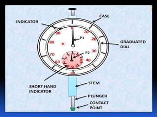
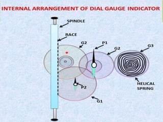
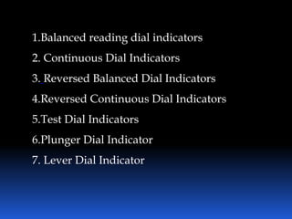
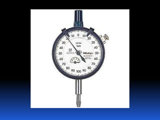
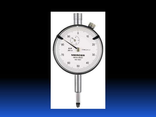
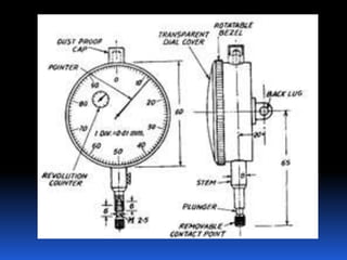
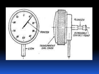
DIAL GAUGE
PRESENTED BY
R.S.MUKESH KUMAR
III RD YEAR
MECHANICAL
ENGINEERING
MEANING OF DIAL GAUGE/ DIAL
INDICATOR
Dial indicators are important devices used in
manufacturing and metal engineering among
others. These devices measure small linear
distances that are important in the establishment
of precision and accuracy.
MAIN COMPONENTS OF DIAL GAUGE
 Circular dial body
 Round graduated dial
 Pointer
 Gear train
 Lever
 Plunger
Types of dial indicators
Several different types of dial indicators exist,
differentiated by factors such as their size,
connection method and the type of information
featured on their face
1.Balanced reading dial indicators
2. Continuous Dial Indicators
3. Reversed Balanced Dial Indicators
4.Reversed Continuous Dial Indicators
5.Test Dial Indicators
6.Plunger Dial Indicator
7. Lever Dial Indicator
1.Balanced reading dial indicators
Balanced reading dial indicators are so
named for the way that information is arranged
upon the dial's face. Figures are printed upon the
face of this dial running in two directions, starting
from a zero in the center. Often, positive numbers
are featured to the right of the zero and negative
numbers to the left.
2. Continuous Dial Indicators
Continuously numbered dial indicators do
not have the two sets of numbers featured on
balanced reading dial indicators. The figures on this
type of dial indicators run in one direction without
stopping and without any type of a separation.
3.Reversed Balanced Dial Indicators
Reversed Balanced Dial Indicators are named
because they have the same basic positive and
negative scales to each side of a zero, but the positive
numbers are to the left and the negative are to the
right.
4.Reversed Continuous Dial Indicators
Reversed continuous, or counter-clockwise,
dial indicators are the same as continuous dial
indicators except that the numbers run in the
opposite direction.
5.Plunger Dial Indicator
Plunger Dial Indicator also have a clock-like
face but are characterized by the plungers mounted
on one of their sides. One common use for plunger
dial indicators is to measure the work of injection
molding machines. The mechanism which allows this
type of dial indicator to work is a rack and pinion,
which changes the linear thrust of the plunger into
rotary motion for the dial.
6.Lever Dial Indicator
Lever Dial Indicator are characterized by
their lever and scroll mechanisms, which cause the
stylus to move. This type of dial indicators are
more compact and easier to use than plunger-type
dial indicators and are therefore quite often used.
APPLICATION
1. Comparing two heights or distances between
narrow limits.
2. To determine the errors in geometrical form
such as ovality, roundness and taper.
3. For taking accurate measurement of
deformation such as intension and
compression.
4. To determine positional errors of surfaces such
as parallelism, squareness and alignment.
5. To check the alignment of lathe centers by
using suitable accurate bar between the centers.
6. To check trueness of milling machine arbours
and to check the parallelism of shaper arm with
table surface or vice.
Advantages
1.The instrument can be easily used and read
even by unskilled worker
2. Contact pressure is low and uniform
3. The instrument is accurate and economical
4. It is easy to handle and can be set very quickly
THANK YOU

Dial gauge

  • 1.
    DIAL GAUGE PRESENTED BY R.S.MUKESHKUMAR III RD YEAR MECHANICAL ENGINEERING
  • 2.
    MEANING OF DIALGAUGE/ DIAL INDICATOR Dial indicators are important devices used in manufacturing and metal engineering among others. These devices measure small linear distances that are important in the establishment of precision and accuracy.
  • 3.
    MAIN COMPONENTS OFDIAL GAUGE  Circular dial body  Round graduated dial  Pointer  Gear train  Lever  Plunger
  • 6.
    Types of dialindicators Several different types of dial indicators exist, differentiated by factors such as their size, connection method and the type of information featured on their face
  • 7.
    1.Balanced reading dialindicators 2. Continuous Dial Indicators 3. Reversed Balanced Dial Indicators 4.Reversed Continuous Dial Indicators 5.Test Dial Indicators 6.Plunger Dial Indicator 7. Lever Dial Indicator
  • 8.
    1.Balanced reading dialindicators Balanced reading dial indicators are so named for the way that information is arranged upon the dial's face. Figures are printed upon the face of this dial running in two directions, starting from a zero in the center. Often, positive numbers are featured to the right of the zero and negative numbers to the left.
  • 10.
    2. Continuous DialIndicators Continuously numbered dial indicators do not have the two sets of numbers featured on balanced reading dial indicators. The figures on this type of dial indicators run in one direction without stopping and without any type of a separation.
  • 12.
    3.Reversed Balanced DialIndicators Reversed Balanced Dial Indicators are named because they have the same basic positive and negative scales to each side of a zero, but the positive numbers are to the left and the negative are to the right.
  • 13.
    4.Reversed Continuous DialIndicators Reversed continuous, or counter-clockwise, dial indicators are the same as continuous dial indicators except that the numbers run in the opposite direction.
  • 14.
    5.Plunger Dial Indicator PlungerDial Indicator also have a clock-like face but are characterized by the plungers mounted on one of their sides. One common use for plunger dial indicators is to measure the work of injection molding machines. The mechanism which allows this type of dial indicator to work is a rack and pinion, which changes the linear thrust of the plunger into rotary motion for the dial.
  • 17.
    6.Lever Dial Indicator LeverDial Indicator are characterized by their lever and scroll mechanisms, which cause the stylus to move. This type of dial indicators are more compact and easier to use than plunger-type dial indicators and are therefore quite often used.
  • 18.
    APPLICATION 1. Comparing twoheights or distances between narrow limits. 2. To determine the errors in geometrical form such as ovality, roundness and taper. 3. For taking accurate measurement of deformation such as intension and compression.
  • 19.
    4. To determinepositional errors of surfaces such as parallelism, squareness and alignment. 5. To check the alignment of lathe centers by using suitable accurate bar between the centers. 6. To check trueness of milling machine arbours and to check the parallelism of shaper arm with table surface or vice.
  • 20.
    Advantages 1.The instrument canbe easily used and read even by unskilled worker 2. Contact pressure is low and uniform 3. The instrument is accurate and economical 4. It is easy to handle and can be set very quickly
  • 21.