A pile integrity test (PIT) is a non-destructive testing method used to assess the integrity of a pile by analyzing its response to an impact or vibration. The test involves striking the pile head with a hammer or applying a vibration to the pile and measuring the resulting waveforms.
The waveforms are recorded using sensors that are attached to the pile and are analyzed using specialized software. The information obtained from the analysis can provide useful information about the structural integrity of the pile, such as the presence of cracks, voids, or other defects.
PIT is commonly used in the construction and engineering industries to assess the quality and integrity of piles in foundation systems for buildings, bridges, and other structures. It is a relatively quick and cost-effective method of testing that can provide valuable information about the condition of a pile without damaging or destroying it.
PIT can be used in combination with other testing methods, such as sonic logging or borehole drilling, to provide a more comprehensive assessment of the pile and the surrounding soil conditions.
#pit #bridgeengineering #civilengineering #nepaliengineer #construction #civilengineer #bridgeengineer #siteengineer #pilefoundation #pilecap #riverbridge #bridge #pit #piletesting #nepalitechnocrats #piling
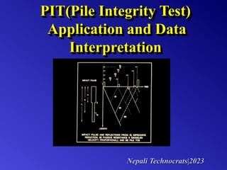
2. Pile Integrity Testing looks for defects
Small hammer
impact device
Accelerometer
measures response
(defect)
One person operation
Nepali
Technocrats|2023
3. PIT-FV/VV PIT-X
PIT-X
• Wireless and Small
• Fixed Sampling Freq.
• Able to adjust senility
• Input of gage SN
Nepali Technocrats|2023
5. PIT motivation and advantages
• prime function is to locate major defects
(to evaluate questionable shafts)
Important
• inexpensive, can test many piles
(good for quality assurance)
• no advance selection required
(good for forensic purposes)
Nepali Technocrats|2023
7. Real data is not perfect
• Imperfect piles
– pile top contact surface not smooth
– inhomogeneous material
(modulus versus length)
– inhomogeneous material (particle sizes)
– Pile shape non-uniform versus length
– pile material damping
– soil resistance
Nepali Technocrats|2023
8. Real data is not perfect
• Imperfect impacts
– spherical point contact versus plane wave
(pile not one dimensional)
– protruding reinforcement “rings”
– Rayleigh waves (surface waves)
– “long” inputs versus “short” defects
Nepali Technocrats|2023
9. Grinding top surface to make flat spot
Pile top preparation is key to good data
which is the key to best interpretation.
Shortcuts cause questionable data.
Nepali Technocrats|2023
10. Minimum Pile Preparation
•locate pile
•clean pile top
•smooth surface
•attach accelerometer
can select any pile to test after installation
(no pre-construction access tubes required)
Nepali
Technocrats|2023
11. Real data is not perfect, so...
“data enhancements” play an
important part in evaluating
low strain integrity tests
• Collect multiple blows:
averaging reduces “random” effects
• Use best possible equipment
low noise, high A/D resolution
signal processing options
Nepali Technocrats|2023
12. Collect Several Blows of Data
No clear toe signal, need more data processing
Same trigger time Nepali Technocrats|2023
18. HI pass filters:
• Removes slow drifts; straightens curve
• Use low values without reducing details
• Avoid very low values that remove detail
(use a value of “HI” that is
at least 10 x the input pulse width)
Nepali Technocrats|2023
19. -0.56
-0.28
0.00
0.28
0.56
4: # 101
cm/s
V 0.360 cm/s (0.375)
43
CAISSON
600MM
07/17/2007 06:49:02 AM
Hi 200.0 m 9.7 Hz
2W 1.00 m 1934 Hz
0 2 4 6 8 10 12 14 16 18 20 22 24 26 28 m
x 15 L/D=16 (D=91.41 cm)
14.90 m (3868 m/s)
Example of Improper Application of Hi Pass Filter (HI)
-0.56
-0.28
0.00
0.28
0.56
4: # 101
cm/s
V 0.360 cm/s (0.375)
43
CAISSON
600MM
07/17/2007 06:49:02 AM
2W 1.00 m 1934 Hz
0 2 4 6 8 10 12 14 16 18 20 22 24 26 28 m
x 15 L/D=16 (D=91.41 cm)
14.90 m (3868 m/s)
-0.56
-0.28
0.00
0.28
0.56
4: # 101
cm/s
V 0.360 cm/s (0.375)
43
CAISSON
600MM
07/17/2007 06:49:02 AM
Hi 50.0 m 38.7 Hz
2W 1.00 m 1934 Hz
0 2 4 6 8 10 12 14 16 18 20 22 24 26 28 m
x 15 L/D=16 (D=91.41 cm)
14.90 m (3868 m/s)
Nepali Technocrats|2023
20. -0.56
-0.28
0.00
0.28
0.56
4: # 101
cm/s
V 0.360 cm/s (0.375)
43
CAISSON
600MM
07/17/2007 06:49:02 AM
Hi 25.0 m 77.4 Hz
2W 1.00 m 1934 Hz
0 2 4 6 8 10 12 14 16 18 20 22 24 26 28 m
x 15 L/D=16 (D=91.41 cm)
14.90 m (3868 m/s)
-0.56
-0.28
0.00
0.28
0.56
4: # 101
cm/s
V 0.360 cm/s (0.375)
43
CAISSON
600MM
07/17/2007 06:49:02 AM
Hi 15.0 m 128.9 Hz
2W 1.00 m 1934 Hz
0 2 4 6 8 10 12 14 16 18 20 22 24 26 28 m
x 15 L/D=16 (D=91.41 cm)
14.90 m (3868 m/s)
Example of Improper Application of Hi Pass Filter (HI)
Nepali Technocrats|2023
21. Example of Improper Application of Hi Pass
Filter (HI)
-0.47
-0.24
0.00
0.24
0.47
4: # 101+1%
cm/s
V 0.360 cm/s (0.375)
Reference
43
CAISSON
600MM
High Pass:1000.0 m 1.9 Hz
Wavelet 1.00 m 1934 Hz
Pivot 1 %
Relative Vol.:
Construct. Vol.:
Construct. Area:
Max Profile:
Min Profile:
1.19
1.00
1.00
1.75 at 9.07 m
0.99 at 5.62 m
0 2 4 6 8 10 12 14 16 18 20 22 m
14.90 m (3868 m/s)
0 5 10 15 20 25 30 35 diam
x 15
Magn
Use of reference line instead of HI
Nepali Technocrats|2023
23. High frequency noise: “noise” or “ringing” complicates
evaluation ( where does noise come from? )
“smoothing” the curve with LoPass filter (“LO”) helps
simplify evaluation
Nepali Technocrats|2023
25. Wavelet (WL) might be more
effective than LO to remove high
frequency noise and smoothen
the curve
Is there an easier and better way
to smooth the curve?
Nepali Technocrats|2023
27. Investigate the cause of “ringing” in this record.
18” augercast pile (38’ long) with 22’ cage #8 bars and 18” stickup. #11
center bar full length – initial 7’ stickup
6#
3#
Nepali Technocrats|2023
28. Investigate the cause of “ringing” in this record.
#11 center bar full length – initial 7’ stickup (trimmed to 3’)
3#
6#
Nepali Technocrats|2023
29. 24” augercast piles
Pile 4
12 ft protruding
rebar
Pile 6
50.5 ft
Pile 7
114.5 ft
(L/D = 57)
( Pile installation was monitored with a PIR-A )
Nepali Technocrats|2023
30. Improperly data processing could lead
to wrong conclusions:
• Magnification(MA and MD):avoid
high MD
• LO Pass or Wavelet filtering (LO or WL)
:avoid high value
• HI Pass(HI):avoid low value
Nepali Technocrats|2023
32. Lesson 1: Location of accelerometer and
force impact make a difference.
Lesson 2: Test at multiple locations at
top of larger diameter shafts.
Lesson 3: Can recommend excavation to
inspect / repair near top defects
Nepali Technocrats|2023
33. Good pile with local bulge
at about 25 ft and clear toe
Major defect
near top
Excavation reveals neck
Nepali Technocrats|2023
34. 1 lb. Hammer
6 lb. Hammer “Pulse width” affects evaluation.
For wide pulse, defect reflection
superimposes on input to make
what looks like extra wide input.
No Defect Pile with Defect near top
Nepali Technocrats|2023
35. If only measure velocity and if pile test
has unusually wide input pulse,
Then pile may have defect near top.
Nepali Technocrats|2023
36. 1 lb hammer 18 lb hammer (92 ft, 72” shaft)
center
north
west
east
south
Larger hammers sometimes makes
inspection of large shafts easier.
Try different hammers on same pile.
Nepali Technocrats|2023
37. Testing same pile with different
hammer sizes is often helpful,
especially for larger, longer piles.
Small hammer to find defects near top
Larger hammer for defects at depth
Nepali Technocrats|2023
38. PIT detected bored pile defect at 4.1 m depth;
confirmed by core
Nepali Technocrats|2023
39. Pile 028
Pile 072
Pile 027
Other piles from
same site:
good pile
pile with bulge
severe defect
near pile top
Nepali Technocrats|2023
40. “We excavated and found some caves.
I could stick my hand all the way to
the middle of the pile and pull out
hand-fulls of soil.”
Nepali Technocrats|2023
41. – Averaging several blows (reduce random noise)
– Magnification versus time (compensate for losses)
– High pass filtering (or pivoting) to remove soil effects
(eliminates very low frequencies; keep data near zero)
– Wavelet filters (or low pass); (use one OR other)
(eliminates very high frequencies from “ringing”)
Conclusions
Important!
• Use similar processing for similar piles in similar soils.
Compare results to spot unusual piles.
• Data processing usually includes:
Nepali Technocrats|2023
42. • Interpretation looks for:
– Good data (consistent & reasonable)
– Similarity or differences for different piles
– Rapidly changing features in data
– Toe signal (tension or compression)
– Shaft uniformity
– Indications of major defects (+/- cycle)
– Comparison with soil profile, installation records
• Integrity testing locates major defects. It is limited to
general interpretations rather than exact detail. Do not
use “heroic effort” to read more than data really tells.
Conclusions
Nepali Technocrats|2023
43. • Some studies suggest a 30 L/D limit.
Actually this is only a “rule of thumb” and
useable length depends on:
– soil strength,
– pile uniformity,
– actual diameter and length,
– and equipment noise, filters and resolution.
• We often see much farther ( even to 60 L/D )
PIT Limitations
• Highly non-uniform piles difficult to interpret
• Cracks or mechanical joints block waves
• Small defects or short length hard to find
• Not always applicable: pile type, walls, in structure
• Says little to nothing about pile capacity
Nepali Technocrats|2023
44. • Compare with other observations
• Re-test with PIT (trim pile top to solid concrete)
• Excavate if near top
• Request pile core
• Request a PDA test or a static test
• Replace pile (or repair)
• Other?
• Have a plan what to do if find a defect
What to do if find a “problem” ?
Nepali Technocrats|2023
45. • Integrity testing is not applicable to ALL situations. Do
not promise results and even try to discourage use in
obviously difficult conditions, or at least inform client of
low possibility of success.
• Impossible to predict load capacity by low strain PIT.
At best, gives relative stiffness from mobility analysis,
or identify soft toes from high toe response.
Conclusions
Nepali Technocrats|2023