Oscillations in Power Systems

This document discusses power system oscillations and their role in power blackouts. It describes different types of oscillations including intraplant, local plant, interarea, control mode, and torsional oscillations. Interarea oscillations in particular have led to many system separations and blackouts around the world. The history of oscillations in the Western Electricity Coordinating Council system is provided as a case study, highlighting how insufficient damping initially limited power transfers, but modifications like installing power system stabilizers improved damping and allowed increased transfers. The 1996 blackout in the WECC region is also summarized, noting discrepancies between actual system behavior and simulation models pointed to the need for more accurate dynamic models.

Recommended
Recommended
More Related Content
What's hot
What's hot (20)
Similar to Oscillations in Power Systems
Similar to Oscillations in Power Systems (20)
More from Power System Operation
More from Power System Operation (20)
Recently uploaded
Recently uploaded (20)
Oscillations in Power Systems
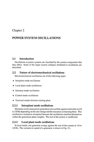
- 1. Chapter 2 POWER SYSTEM OSCILLATIONS 2.1 Introduction Oscillationsin power systems are classified by the systemcomponentsthat they effect. Some of the major system collapses attributed to oscillations are described. 2.2 Nature of electromechanicaloscillations Electromechanical oscillationsare of the following types: B Intraplant mode oscillations rn Local plant mode oscillations Interarea mode oscillations rn Control mode oscillations rn Torsional modes between rotating plant 2.2.1 Intraplant mode oscillations Machinesonthesamepowergenerationsiteoscillateagainsteachotherat2.0 to 3.0Hz depending on theunit ratings and thereactanceconnectingthem. This oscillationis termed as intraplant because the oscillationsmanifest themselves within the generation plant complex. The rest of the systemis unaffected. 2.2.2 Local plant mode oscillations In local mode, one generator swings against the rest of the system at 1.0to 2.0 Hz. The variation in speed of a generator is shown in Fig. 2.1.
- 2. ROBUST CONTROLIN POWER SYSTEMS 376 0 2 4 6 8 10 time, s Figure 2.1. A typical exampleof local oscillation The impact of the oscillation is localized to the generator and the line con- necting it to the grid .The rest of the systemis normally modelled as a constant voltage source whose frequency is assumed to remain constant. This is known as the single-machine-infinite-bus(SMIB) model. The dampingand frequency vary with machineoutput and theimpedancebetween the machine terminal and the infinite bus voltage. The oscillation may be removed with a single or dual input PSS that provides modulation of the voltage reference of the automatic voltageregulator(AVR) with proper phase and gain compensationcircuit [Lee, 19921. 2.2.3 Interarea mode oscillations This phenomenon is observed over a large part of the network. It involves two coherent group groups of generators swinging against each other at 1Hz or less. The variation in tie-line power can be large as shown in Fig. 2.2. The oscillationfrequency is approximately 0.3 Hz. This complex phenomenon involves many parts of the system with highly non-linear dynamicbehavior. Thedampingcharacteristicof theinterareamode is dictated by the tie-line strength, the nature of the loads and the power flow
- 3. Power System Oscillations time, s Figure 2.2. A typical example of interarea oscillation through the interconnection and the interaction of loads with the dynamics of generators and their associated controls. The operation of the system in the presence of a lightly damped interarea mode is very difficult. 2.2.4 Control mode oscillations These are associated with generators and poorly tuned exciters, governors, HVDC converters and SVC controls. Loads and excitation systems can interact through control modes [Rajagopalan et al., 19921. Transformer tap-changing controls can also interact in a complex manner with non-linear loads giving rise to voltage oscillations [Cutsem and Vournas, 19981. 2.2.5 Torsional mode oscillations These modes are associated with a turbine generator shaft system in the fre- quency range of 10-46Hz. A typical oscillation is shown in Fig. 2.3. Usually these modes are excited when a multi-stage turbine generatoris con- nected to the grid system through a series compensated line [Padiyar, 19991. A mechanical torsional mode of the shaft system interacts with the series ca- pacitor at the natural frequency of the electrical network. The shaft resonance appears when network natural frequency equals synchronous frequency minus torsional frequency.
- 4. ROBUST CONTROLIN POWER SYSTEMS time (sec) Figure 2.3. A typical example of torsional mode oscillation 2.3 Role of Oscillationsin Power Blackouts Interareaoscillationshave ledtomany systemseparationsbut few wide-scale blackouts [Pal, 1999,Paserba, 19961. Note worthy incidents include: rn DetroitEdison (DE-OntarioHydro(OH)-HydroQuebec(HQ)(1960s, 1985) rn Finland-Sweden-Norway-Denmark(1960s) rn Saskatchewan-ManitobaHydro-Western Ontario (1966) rn Italy-Yugoslavia-Austria(1971-1974) rn Western Electric CoordinatingCouncil (WECC)(1964,1996) rn Mid-continent area power pool (MAPP) (1971,1972) rn South East Australia (1975) rn Scotland-England(1978) rn Western Australia (1982,1983) rn Taiwan (1985) rn Ghana-Ivory Coast (1985)
- 5. Power System Oscillations 9 = SouthernBrazil (1975-1980,1984) Thepowerblackout of August 10,1996in theWesternElectricityCo-ordination Council (WECC) (formerly WSCC) area is described below. It indicates the importanceof understanding and managing oscillationsfor secureoperation of the grid. 2.3.1 Oscillations in the WECC system Power transfer capability in this system has been limited by stability con- siderationsfor 40 years because of the long distancebetween load centers and power sources. Oscillationshave resulted in system separation on several oc- casions. They were caused by insufficient damping and synchronizingtorque. The history of interarea oscillations in this system has influenced the system planning, design and operation strategy. Insufficientdamping turned out to be the major constraintwhen in 1964,the Northwest United States and Southwest United States were interconnected through the ColoradoRiver StorageProject. In less than a year of interconnected operation, there were at least a hundred tie-line separationsdue to system oscillationsof power, frequency and voltage. In 1965,the problem was solvedby modificationsto one of the hydro-unit gov- ernors [Schleif et al., 19671. About that time work was initiated to develop time domain stability pro- grams for more detailed analysis of interconnected systems. This was very useful since it coincided with the planning of many 345 kV and 500 kV trans- mission projects, including the Northwest-Southwest Inter-tie which consisted of two 500 kV ac lines and f400 kV dc circuits. The initial plan was to carry 2000 MW through the ac circuits and 1440MW through the dc line. Stability performance assessment showed that there was insufficientdampingtorquefor ac power flowsexceeding 1300MW. It was foundfromthestudythat undamped oscillations of power, frequency and voltage at about 0.33 Hz was the major restrainton a largertransfer [SchleifandWhite, 19661. It was later realized that many of the generatorhigh gain automatic voltage regulators (AVR) produced negativedampingat around 0.33 Hz which led to the development and applica- tion of PSS. It was found from the time domain simulationsthat there would be sufficient damping for the most severe disturbancewith 1800MW transferred through the ac lines if all generators in the system were equipped with PSS. After all the units were retrofitted with PSS, the oscillations disappeared and the stabilitylimit depended only upon the synchronizingtorque. The Bonneville Power Authority (BPA) implemented a 1400MW braking resistor at Chief Joseph Dam in 1974 to improve first swing stability of the system. This indicated that the system could operate with up to 2500 MW
- 6. 10 ROBUST CONTROLIN POWER SYSTEMS flowing through the AC interconnection with adequate stabilitymargin follow- ing a severe disturbancessuch as a close in three phase fault. With even higher loading, however, slowly growing oscillations were observed, indicating that insufficient damping torque was again a problem at the higher loading level. The problem was relievedby the developmentof a scheme [Cresapet al., 19781 to modulate the northern terminal of the Northwest-Southwest dc line in such a manneras toprovidepositivedampingto theac systemattheinter-tiefrequency. Overall the transmission capacity was increased from 1300 MW to 2500 MW without adding any transmission circuits. The only systemadditionswere PSS, braking resistors and HVDC modulation. Many other interfacesin west- ern USA are limited by insufficient damping torque and are highly dependent on PSS and other devices to provide positive damping. Currentlythere is a 0.7 Hz lightly damped interareamodeidentifiedfromsystemmodels and analytical techniques. In one interface,nearly 750 Mvar of static VAr compensatorshave been installed to add damping so that the full planned transmission capacity will be available [Lee et al., 19941. On August 10, 1996,the Pacific AC inter-tie (PACI) emerged from the dor- mant state that had lasted since 1974 when the entire inter-connected system splitinto four islands with the loss of approximately 30 GW of load. More than 7 million customers were affected by this catastrophic event [Kosterev et al., 19991. The mechanism of failure was a transient oscillation,under conditions of high power transfer on long paths that had been progressively weakened through a series of fairly routine resource losses. This series of events was simulated based on the dynamicmodel data base with data assembled from the data bases of the utilities. The simulation showed a well damped response for the critical set of contingenciesbut did not show any voltage decay. The power flow through the pacific HVDC tie was observed constant because of constant power control in the simulation model. The simulatedfrequency dip was also only 60% of the recorded value. On the other hand, undamped oscillations in the inter-tiepower flow were recorded whilst voltages at several locationswere depressed. Also the power flow through the HVDC tie was observed to vary thereby showing a serious discrepancy between the simulation model and the actual systemdynamiccharacteristics. The oversimplifiedmodel of theHVDC tie and its control were replaced with four-terminal links and control at con- verter levels. The automatic governor control (AGC) was included during the transient which is normallyomittedfromdynamicsimulations. Thepresence of large turbo-generators delayed the power output pick-up immediately follow- ing a frequency decay. This was done by not representing the governor action for large units. With all these modifications, the simulated system response
- 7. REFERENCES 11 differed appreciably from the recorded observationuntil a dynamicload model was included. 2.4 Summary The long history of interarea oscillations in the WECC system and other interconnected systems,[Paserba,19961,clearlyidentifiesinadequatedamping as the primary factor leading to system separation. The amount of damping and the frequency of oscillation varies with system operating conditions. The operatingrangeof a power system is usually very wide, requiring an oscillation dampingcontrol strategy that is effectiveover this whole range. It is necessary tohavecomprehensivemodellingand analysistechniques of all thecomponents that may interact to produce oscillations. References [Cresap et al., 19781 Cresap, R.L., Scott, D.N., Mittelstadt, W.A., and Taylor, C.W. (1978). Dampingof pacific acintertieoscillationsvia modulationof the parallel pacifichvdcintertie. CIGREPaper, 14(5). [Cutsem and Vournas, 19981 Cutsem,T Van andVournas,C(1998). VoltageStability of Electric Power Systems. Kluwer Academic Press, USA. [Kosterevet al., 19991 Kosterev, D.N., Taylor, C.W., and Mittelstadt,W. (1999). Model vali- dation for the august 10, 1996wscc systemoutage. IEEE Transactions on Power Systems, 14(3):967-979. [Lee, 19921 Lee, D.C. (1992). IEEE recommended practice for excitation system modelsfor power system stability studies. Energy development and power generation committee of power engineeringsociety. [Lee et al., 19941 Lee, R.L., Beshir, M.J., Finely, A.T., Hayes,D.R., Hsu, J.C., Peterson,H.R., Deshazo, C.L., and Gerlach, D.W. (1994). Application of static var compensator for the dynamicperformanceof the mead-adelanto and mead-phoenix transmission projects. IEEE PES T and D Conference and Exposition, Chicago,ZL. [Padiyar, 19991 Padiyar,K.R. (1999).AnalysisofSubsynchronous Resonance inPowerSystems. Kluwer Academic Publishers,USA. [Pal, 19991 Pal, B.C. (1999). Robust Damping Control of Inter-area Oscillations in PowerSys- tem with Super-conducting Magnetic Energy Storage Devices. PhD thesis,Imperial College of ScienceTechnology and Medicine, Department of Electrical and ElectronicEngineering. [Paserba, 19961 Paserba,J. (1996). Analysis and control of power systemoscillation. CIGRE Special Publication 38.01.07,Technical Brochure 111. [Rajagopalan et al., 19921 Rajagopalan, C., Lesieutre, B., Sauer, PW., and Pai, M.A. (1992). Dynamic aspects of voltagelpower characteristicsin multi-machine power systems. IEEE Transactions on Power Systems, 7(3):99&1000.
- 8. 12 ROBUST CONTROLIN POWER SYSTEMS [Schleif et al., 19671 Schleif, F.R., Martin, G.E., and Angell, R.R. (1967). Damping of sys- tem oscillationswith a hydro-generating unit. IEEE Transactionson Power Apparatus and Systems, 86(4):438-442. [Schleif and White, 19661 Schleif, F.R. and White, J.H. (1966). Damping for northwest- southwesttie line oscillations- an analogue study. IEEE Transactionson Power Apparatus and Systems, 85(12):1234-1247.