
Recommended
Recommended
More Related Content
What's hot
What's hot (19)
Similar to Cohesive Zone Modeling of Laminated Composite Beam under Mixed Mode Bending Load
Similar to Cohesive Zone Modeling of Laminated Composite Beam under Mixed Mode Bending Load (20)
More from NEERAJKUMAR1898
More from NEERAJKUMAR1898 (16)
Recently uploaded
Recently uploaded (20)
Cohesive Zone Modeling of Laminated Composite Beam under Mixed Mode Bending Load
- 1. Dogo Rangsang Research Journal UGC Care Group I Journal ISSN : 2347-7180 Vol-10 Issue-09 No. 03 September 2020 Page | 138 Copyright @ 2020 Authors Cohesive Zone Modeling of Laminated Composite Beam under Mixed Mode Bending Load Gousia Nabi Dar1 , Er. Neeraj Kumar2 1,PG SCHOLAR,DEPARTMENT OF MECHANICAL ENGINEERING, R N COLLEGE OF ENGINEERING & TECHNOLOGY, MADLAUDA, PANIPAT 2,ASSISTANT PROFESSOR, DEPARTMENT OF MECHANICAL ENGINEERING, R N COLLEGE OF ENGINEERING & TECHNOLOGY, MADLAUDA, PANIPAT Email id :- gousianabi92@gmail.com Abstract In the present work, the finite element method based computational tool- COMSOL Composite beam to study the effect of variation of thickness of laminates on the debonding, also the effect of initial crack length on the debonding is presented. The whole study involves the simulation of the mixed mode bending (MBB) test of composite beam of AS4 / PEEK material. There is a significant impact of laminate thickness on the phenomenon of crack propa- gation (debonding) i.e. with the increase in thickness of laminates, the von Mises stresses also increase significantly resulting in delamination propagation especially at higher lam- inate thickness, beyond 7 mm, the increase in maximum stress is rampant thus resulting in rapid yeilding of adhesive bond. The interface health is also affected with the increase in laminate thickness. Also, the initial crack length (ICL) variation results in the change in transverse deflection of the beams, at lower ICL, the vertical deflection at centre is more as compared to that at higher values of ICL. Keywords :- Composite, Debonding, Delamination, Finte Element Method, Lami- nate thickness, MBB test 1. INTRODUCTION The advancements of composite materials in the field of aerospace engineering has poured down rapidly and in large quantities trying to satisfy the demand in domestic and indus- trial applications. Composites, the marvel material has the properties of light in weight, high strength-to-weight ratio and stiffness have replaced the materials like metals, wood to a large extent. A characteristic property of composite materials is that the finished products can be costumed according to the specifications required by selecting the proper type of matrix and the type of reinforcement. A. Delamination of Composite Delamination is a failure which affects the structural performance the composite materials and differentiates it from metallic structures. Delaminations arise from the manufactur- ing imperfections; cracks are generated from fatigue or impact, stress concentration near the joints and high inter-laminar stresses. Delamination affects the compressive strength and it will cause the material to fail through buckling. Delamination is a phenomenon of damage in the laminated composite materials which arise due to weakness of reinforce- ment through the thickness. The study of the delamination of a laminate is done by performing an approach of fracture mechanics or by introducing appropriate constitutive laws of the interface between the layers which constitute the laminate. It is not necessary that delamination will occur only when the stresses are highest. Delamination is one of the paramount and common types of damage in laminated composites caused due to their relatively weak inter - laminar strengths. The stresses which govern the delamina- tion initiation are the out-of-plane stresses, and are usually referred to as inter-laminar stresses. Delamination initiates at the geometrical discontinuities, such as laminate free edges and cut outs. This happens because the state of stress close to a free edge in a
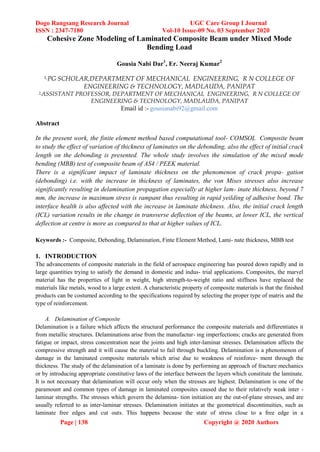
- 2. Dogo Rangsang Research Journal UGC Care Group I Journal ISSN : 2347-7180 Vol-10 Issue-09 No. 03 September 2020 Page | 139 Copyright @ 2020 Authors laminate.Combined buckling resulting into multiple delaminations are also analysed and the experimental results are also presented. Other type of delamination configurations are beam-type delaminations resulting from shear or axial loading. The rate of energy release G is used to describe the behaviour of the phenomenon of composites. The rate of energy release is the amount of energy released by the fractured structure and is calculated from force and nodal displacements. Composite structures often contain delamination. Causes of delamination are tool drops, bird strikes, runway debris hits and manufacturing defects. In some cases, like in the areas of holes or close to edges, delamination initiates as result of the development of inter laminar stresses. A large number of analyses have been reported on the pretext of edge delamination and its significance in the design of laminated structures. This delaminating is also present before the laminate is loaded or it develops after loading because of foreign body (birds, micrometer, and debris) impact. This is a problem especially for laminated structures that are subjected to destabilizing loads (loads can induce instability in the structure and cause growth of the delamination; both of these phenomena contribute to failure of the laminate). The presence of delamination in many situations can cause local buckling and / or trigger global buckling and therefore induce a reduction in the overall load – bearing capacity of the laminated structure. B. Debonding of Composites Debondingoccurs when an adhesive does not stickto anadherent or substrate material. The adhesive need not to be an organic, polymeric material; it can be an inorganic coating. Debondingtakes place when the physical, chemical or mechanical forces which hold the bond together are broken down, either by a force or environmental attack. It is the debounding that leads to delamination. The defects which occur in adhesive bonds are given below which shows debounding in the form of disbonds Figure 1: Debonding in Composites 2. MATERIALS AND METHODS A. Finite Element Formulation Definition of the laws of physics for space-and time-dependent problems is generally ex- pressed in terms of partial differential equations (PDEs). Such PDEs can not be solved with analytical modeling for the vast majority of geometries and problems. Instead, an approximation of equations can be constructed, usually based
- 3. Dogo Rangsang Research Journal UGC Care Group I Journal ISSN : 2347-7180 Vol-10 Issue-09 No. 03 September 2020 Page | 140 Copyright @ 2020 Authors on different types of discretizations. Such discretion methods approximate PDEs with numerical model equa- tions, which can be resolved using numerical methods. The solution for numerical model equations is, in effect, the approximation of the real solution to the PDEs. The Finite Element Method (FEM) is used to measure these approximations As it includes all the details on the FEM application for an interconnect analysis, it is easy to split it into smaller sub-steps. The first sub-step includes constructing an interconnect geometry (1D, 2D, or 3D), describing the domain under analysis, and assigning the properties of the material to the domain. The detailed characterization of the problem at hand are then generated by applying the underlying physics (or multiphysics), mathematical notation, and finite element formulation to the framework. B. Geometry and Materials The model geometry is a beam of length lb, height hb and width wb. Due to symmetry only half of the beam is drawn and a Symmetry boundary condition is applied (see Figure 2). There is an initial crack of length cl halfway through the thickness. The beam is supported at the outermost bottom edges. A mixed-mode bending load is the result of forces applied to the top edges at the cracked end and at the center of the beam. The material of the beam is AS4/PEEK, cohesive interface properties of which are The material properties are those of AS4/PEEK unidirectional laminates. The orthotropic linear elastic properties are listed in Table, assuming that the longitudinal direction is aligned with the global x-direction. Figure 2: Geometry of half symmetric laminated composite beam Table 1: Materials Properties Property Symbol Value Normal tensile strength Ns 80 MPa Shear strength Ss 100 MPa Penalty stiffness Kp 106 N/mm3 Mode I critical energy release GIc 969 J/m2 Mode II critical energy release GIIc 1719 J/m2 Exponent of Benzeggagh and Kenane (B-K) criterion η 2.284
- 4. Dogo Rangsang Research Journal UGC Care Group I Journal ISSN : 2347-7180 Vol-10 Issue-09 No. 03 September 2020 3. BOUNDARY CONDITIONS In the mathematical analysis of partial differential equations, the boundary conditions of the Dirichlet, Neumann and Robin forms will be encountered. With the Dirichlet condition, we ’re going to prescribe the variable we ’re going to solve. In the meantime, the Neumann condition is used to prescribe a flow, that is, a gradient of the dependent variable. A Robin condition is a mixture of the two previous boundary condition types, where the relationship between the variable and its gradient is prescribed. The Neumann conditions are ”loads” and appear on the right side of the equation system. InCOMSOL Multiphysics, we can see them as a weak contribution to the Equation View. Since the Neumann conditions are strictly additive inputs to the right- hand side, they that include any variable function: time, coordinate, or parameter values. When a Dirichlet condition is defined, the dependent variable is prescribed, so there is no need to solve it. Therefore, equations for these degrees of freedom can be excluded from the problem. Dirichlet conditions therefore alter the configuration of the rigidity matrix. When viewing the Equation View of COMSOL Multiphysics, these conditions should appear to be restriction. In general, the Robin conditions apply to both the stiffness matrix and the right-hand side. The composition of the stiffness matrix is not changed, but the values are applied to the current positions. The Robin conditions also tend to be weak contributions in the Equation View. To transform these conditions into functions of time, space, and other variables is no different than to do so under the Neumann conditions. It is interesting, however, that by choosing correct values, we can actually transform Robin’s conditions into approximate Dirichlet or Neumann ’s conditions. It is especially important in cases where we want to distinguish between the two types of boundary conditions during a simulation. A. Meshing Meshing is an important part of the engineering simulation process, where complex ge- ometries are divided into simple elements that can be used as discrete local approxima- tions of the larger domain. The mesh affects the precision, consistency and speed of the simulation. Various parameters related to meshing (mesh statistics and size settings) of domain (composite beam in present study). 4. RESULTS AND DISCUSSIONS The results of the study in the form of contours and plots showing various aspects of the study involving laminated composite beams. The various results obtained are ; stress distribution in the laminated beam under MMB test, crack propa- gation in the laminate structure, health of the interface under the variation of thickness of the beam and initial crack length, maximum stress variation under the variation of thickness of the beam and initial crack length etc. A. Von Mises stress distribution as a functionof laminate thickness von Mises Criteria (Distortion Energy Criteria) states that failure occurs when equivalent stress (von Mises stress) reaches the yield stress of the material. It (criteria) also suggests a failure or yielding when the elastic energy of distortion reaches a critical value. There- fore, von Mises criteria is also known as maximum distortion energy criteria. Figures 4.1 to 4.7 show the respective von Mises stresses of the laminated beams of thicknesses, 2mm, 3mm, 4mm, 5mm, 6mm, 7mm and 8mm. It is observed that the beam thicknesses beyond 6mm show very high value of von Mises stress because the resistance of individual laminates to bending also adds to the strength of the composite beam.
- 5. Dogo Rangsang Research Journal UGC Care Group I Journal ISSN : 2347-7180 Vol-10 Issue-09 No. 03 September 2020 Page | 142 Copyright @ 2020 Authors Figure 3 : von Mises stress distribution at beam thickness=2 mm Figure 4: vonMises stress distribution at beam thickness=3 mm Figure 5: vonMises stress distribution at beam thickness=4 mm
- 6. Dogo Rangsang Research Journal UGC Care Group I Journal ISSN : 2347-7180 Vol-10 Issue-09 No. 03 September 2020 Page | 143 Copyright @ 2020 Authors Figure 6: vonMises stress distribution at beam thickness=5 mm Figure7: vonMisesstressdistributionatbeamthickness=6mm Figure 8: von Mises stress distribution at beam thickness=7 mm
- 7. Dogo Rangsang Research Journal UGC Care Group I Journal ISSN : 2347-7180 Vol-10 Issue-09 No. 03 September 2020 Page | 144 Copyright @ 2020 Authors Maximum Stress [Mpa] Figure 9: von Mises stress distribution at beam thickness=8 mm 380 360 340 320 300 280 260 240 2 3 4 5 6 7 8 Laminated Beam Thickness, mm Figure 10: Maximum stress distribution as a function of laminated beam thickness B. Interface health as a function of laminated beam thickness The health of the laminate interface under different thicknesses of the laminates of the beam, where red colour represents the debonded area and green colour signifies the intactness of the interface , it is evident that as the thickness of the beam increases, the debonding and delamination propagates at constant loading under MMB test.At higher thicknesses, the bending of the beam does not occur which results in bulk detachment of the adhesive bond. At lower thicknesses, MMB test results in bending of the beam as well thus there is less debonding in that case. Maximum Stress, MPa
- 8. Dogo Rangsang Research Journal UGC Care Group I Journal ISSN : 2347-7180 Vol-10 Issue-09 No. 03 September 2020 Page | 145 Copyright @ 2020 Authors Figure 11: Interface health as a function of laminated beam thickness, a=2mm, b=3mm, c=4mm, d=5mm, e=6mm,f=7mm and g=8mm
- 9. Dogo Rangsang Research Journal UGC Care Group I Journal ISSN : 2347-7180 Vol-10 Issue-09 No. 03 September 2020 Page | 146 Copyright @ 2020 Authors C. Load point displacement variation with laminate thickness One of the outputs of the MMB test is a load-displacement curve. Both load and displace- ment are measured at the end point of the lever that is used to apply the load to the test specimen. Since the lever is not explicitly modeled in this study, the load-displacement data has to be deduced from the simulation results using the equations 3.13,3.14 and 3.15. From the Figure 4.10, it is observed that for delamination to occur at higher lami- nate thickness (greater than 5mm), load point displacement is low which means that the adhesive debonding is pervasive to greater area of the interface which is also evident from the Figure 4.9, more the thickness, poor the interface health. 1800 1600 1400 1200 1000 800 600 400 200 0 -200 Load Point Displacement, mm Figure 12 : Load point displacement as a function of laminated beam thickness D. von Mises stress distribution as a function of ini- tial crack length It is observed that lesser the initial crack length, more is the transverse deflection at the centre of the beam, Figure 4.11 clearly shows that at ICL = 5mm, the maximum stress is 621 MPa at the centre of the beam. Figures 4.12 to 4.18 clearly depict that as the ICL Interfacehealth asafunctionof initialcracklength As compared to variation of interface health with respect to change in laminate thickness, there is a different trend in the same when ICL is varied. 0 1 2 3 4 5 6 Thickness 2mm Thickness 3 mm Thickness 4 mm Thickness 5 mm Thickness 6 mm Thickness 7 mm Thickness 8 mm Load, N
- 10. Dogo Rangsang Research Journal UGC Care Group I Journal ISSN : 2347-7180 Vol-10 Issue-09 No. 03 September 2020 Page | 147 Copyright @ 2020 Authors Figure 13: von Mises stress distribution at initial crack length =8 mm Figure 14: von Mises stress distribution at initial crack length =10 mm
- 11. Dogo Rangsang Research Journal UGC Care Group I Journal ISSN : 2347-7180 Vol-10 Issue-09 No. 03 September 2020 Page | 148 Copyright @ 2020 Authors Figure 15: von Mises stress distribution at initial crack length =12 mm Figure 16: von Mises stress distribution at initial crack length =15 mm
- 12. Dogo Rangsang Research Journal UGC Care Group I Journal ISSN : 2347-7180 Vol-10 Issue-09 No. 03 September 2020 Page | 149 Copyright @ 2020 Authors Figure 17: von Mises stress distribution at initial crack length =28 mm Figure 18: von Mises stress distribution at initial crack length =30 mm
- 13. Dogo Rangsang Research Journal UGC Care Group I Journal ISSN : 2347-7180 Vol-10 Issue-09 No. 03 September 2020 Page | 150 Copyright @ 2020 Authors Figure 19: von Mises stress distribution at initial crack length =34 mm 700 600 500 400 300 200 Initial Crack Length, mm Figure20: Maximum stress distribution as a function of initial crack length Maximum Stress,MPa 5 10 15 20 25 30 35 Maximum Stress, MPa
- 14. Dogo Rangsang Research Journal UGC Care Group I Journal ISSN : 2347-7180 Vol-10 Issue-09 No. 03 September 2020 Page | 151 Copyright @ 2020 Authors there is not a significant impact of ICL on debonding, but from ICL = 28mm to 34mm, the debonding increases significantly, this observation is further corroborated by the load point displacement. Figure 21: Interface health at various values of initial crack length, a= 5mm, b=8mm, c=10mm, d=12mm, e=15mm, f=28mm, g=30mm and h=34mm D. Load point displacement variationwith initial crack length The straight curves in the figure correspond to the ICL = 5mm, 8mm, 10mm, 12mm and 15mm and attest the fact that debonding does not occur at lower ICL values but at
- 15. Dogo Rangsang Research Journal UGC Care Group I Journal ISSN : 2347-7180 Vol-10 Issue-09 No. 03 September 2020 Page | 152 Copyright @ 2020 Authors ICL5 ICL8 ICL10 ICL12 ICL15 ICL28 ICL30 ICL34 higher ICL values 28mm, 30mm and 34mm represented by the upward kinks in the figure 4.21. 600 500 400 300 200 100 0 0 1 2 3 4 5 6 Load Point Displacement, mm Figure22: Load point displacement as a function of initial crack length, ICL 5. CONCLUSION Following concluding remarks can be made with regard to present study: There is a prominent influence of laminate thickness on the maximum stress (von Mises stress) which a beam can carry under constant load on the sidelines of mixed mode bending test simulated by Comsol Multiphysics. There is a significant influence of laminate thickness on the interface Comsol Multiphysics can simulate the mixed mode bending (MMB) test without actually designing the experimental setup, only the domain geometry is drawn and loads and BCs applied to study the fracture behaviour of the composite beam. Load point displacement calculation needs to have all the lengths of the experi- mental setup in actual laboratory experimentation procedures e.g. lever length et cetera, but, here the same can be calculated by using the simulation results as per the equations 3.1 to 3.15 There is a prominent influence of variation of ICL on the maximum stress (von Mises stress) which a beam can carry under constant load on the sidelines of mixed mode bending test simulated by Comsol Multiphysics. There is not a significant impact of variation of initial crack length on the interface health which is clearly depicted by the results. Load, N
- 16. Dogo Rangsang Research Journal UGC Care Group I Journal ISSN : 2347-7180 Vol-10 Issue-09 No. 03 September 2020 Page | 153 Copyright @ 2020 Authors Future Scope There is always a scope for improvement, therefore this work is no exception, following are the various developments which can result in fruitful conclusions if incorporated in the study: Only one material, AS4/PEEK has been tested using MMB test, other composite materials can also be studied to study their fracture behaviour. There are other tests also like double cantilever beam (DCB) which can also be simulated through Comsol Multiphysics. Symmetric boundary conditions were applied to save the computational time and effort, a full scale (3D) test can be administered to study other parameters as well. Other softwares like Abaqus, ANSYS (Static Structural) , Ansys Parametric Design Language or MATLAB coding can be utilized to arrive at better accuracy by using different meshing elements available in different commercial codes. Recently developed techniques like NURBS (Non Uniform Rational B-Spline) based Isogeometric analysis can be used to improve the accuracy of the results. References 1. Idowu D Ibrahim et al. “The use of polypropylene in bamboo fibre composites and their mechanical properties–A review”. In: Journal of Reinforced Plastics and Composites 34.16 (2015), pp. 1347–1356. 2. Holm Altenbach and Johannes Altenbach. Mechanics of composite structural ele- ments. Springer, 2004. 3. Raymond Benedict Seymour et al. History of polymer science and technology. 1982. 4. AE Jartiz. Design. 1965. 5. Anthony Kelly. “The nature of composite materials”. In: Scientific American 217.3 (1967), pp. 160–179. 6. A Berghezan. “Non-ferrous materials”. In: Nucleus 8.5 (1966), pp. 5–11. 7. J Van Suchtelen. “Product properties: a new application of composite materials”. In: Philips Res. Rep 27.1 (1972), pp. 28–37. 8. Denis DR Carti´e. “Effect of z-fibresTM on the delamination behaviour of carbon- fibre/epoxy laminates”. PhD thesis. Cranfield University, 2000. 9. Bhavam V Sankar and Shoufeng Hu. “Dynamic delamination propagation in com- posite beams”. In: Journal of composite materials 25.11 (1991), pp. 1414–1426. 10. P Robinson and S Das. “Mode I DCB testing of composite laminates reinforced with z- direction pins: a simple model for the investigation of data reduction strategies”. In: Engineering Fracture Mechanics 71.3 (2004), pp. 345–364. 11. Larry W Byrd and Victor Birman. “The estimate of the effect of z-pins on the strain release rate, fracture and fatigue in a composite co-cured z-pinned double cantilever beam”. In: Composite Structures 68.1 (2005), pp. 53–63. 12. JG Ratcliffe and R Krueger. “A Finite Element Analysis for Predicting Mode I- Dominated Delamination Growth in Laminated Structure with Through-Thickness Reinforcement”. In:
- 17. Dogo Rangsang Research Journal UGC Care Group I Journal ISSN : 2347-7180 Vol-10 Issue-09 No. 03 September 2020 Page | 154 Copyright @ 2020 Authors Failure in Composites 4 (2013), p. 117. 13. Venkata Dantuluri et al. “Cohesive modeling of delamination in Z-pin reinforced composite laminates”. In: Composites science and technology 67.3-4 (2007), pp. 616– 631. 14. Marcello Grassi and Xiang Zhang. “Finite element analyses of mode I interlaminar delamination in z-fibre reinforced composite laminates”. In: Composites science and technology 63.12 (2003), pp. 1815–1832. 15. P Uniyal and A Misra. “Finite element analysis of laminated composite cantilever beam”. In: International Journal of Advancements in Technology 7.4 (2016), pp. 1– 4. 16. Li Jun, Hua Hongxing, and Shen Rongying. “Dynamic finite element method for generally laminated composite beams”. In: International Journal of Mechanical Sciences 50.3 (2008), pp. 466–480. 17. Yuan Fuh-Gwo and Robert E Miller. “A new finite element for laminated composite beams”. In: Computers & structures 31.5 (1989), pp. 737–745. 18. S Stoykov and S Margenov. “Nonlinear vibrations of 3D laminated composite beams”. In: Mathematical Problems in Engineering 2014 (2014). 19. Ida Mascolo et al. “A Finite Element Analysis of the Stability of Composite Beams With Arbitrary Curvature”. In: Frontiers in Built Environment 4 (2018), p. 57. 20. V Kahya and M Turan. “Bending of laminated composite beams by a multi-layer finite element based on a higher-order theory”. In: Acta Physica Polonica A 132.3 (2017), pp. 473– 475. 21. Nitin Jauhari, Raghvendra Mishra, and Harischandra Thakur. “Stress analysis in FRP composites”. In: Perspectives in Science 8 (2016), pp. 50–52. 22. Kalyana Chakravarthy and K Raghunandana. “Stress analysis of glass fibre rein- forced composites used in wind turbines”. In: (2015). 23. SushilB Chopade, KM Narkar, and Pratik K Satav. “Design and Analysis of E- Glass/Epoxy Composite Monoleaf Spring for Light Vehicle”. In: Int. J. Innov. Res. Sci. Engg. Technol 4.1 (2015), pp. 18801–18808. 24. Esmael Adem et al. “Experimental Analysis of E-Glass/Epoxy & E-Glass/polyester Composites for Auto Body Panel”. In: American International Journal of Research in Science, Technology, Engineering & Mathematics 10.4 (2015), pp. 377–383. 25. Deepanshu Bhatt, Yogesh Mishra, and Dr PK Sharma. “A Review of Static and Free Vibration Analysis of Laminated Composite Plate by using Finite Element Method”. In: International Journal of Advanced Engineering and Global Technology 2 (). 26. Ashwani Kumar et al. “Free vibration analysis of Al 2024 wind turbine blade de- signed for Uttarakhand region based on FEA”. In: Procedia Technology 14 (2014), pp. 336–347. 27. Sharayu U Ratnaparkhi and SS Sarnobat. “Vibration analysis of composite plate”. In: International Journal of Modern Engineering Research (IJMER) 3.1 (2013), pp. 377–380. 28. Rasoul Ghayour, Mostafa Ghayour, and Saeed Ziaei-Rad. “Vibration analysis of tapered rotating composite beams using the hierarchical finite element”. In: (2010). 29. Jifeng Wang, Jorge Olortegui-Yume, and Norbert Mu¨ ller. “Stress and vibration analysis for woven composite axial impeller”. In: Power Conference. Vol. 49354. 2010, pp. 443–449.
- 18. Dogo Rangsang Research Journal UGC Care Group I Journal ISSN : 2347-7180 Vol-10 Issue-09 No. 03 September 2020 Page | 155 Copyright @ 2020 Authors 30. Mehmet Akta¸s et al. “An experimental investigation of the impact response of composite laminates”. In: Composite Structures 87.4 (2009), pp. 307–313. 31. HBH Gubran and K Gupta. “The effect of stacking sequence and coupling mech- anisms on the natural frequencies of composite shafts”. In: Journal of sound and vibration 282.1-2 (2005), pp. 231–248. 32. M Heidari-Rarani, SS Khalkhali-Sharifi, and MM Shokrieh. “Effect of ply stacking sequence on buckling behavior of E-glass/epoxy laminated composites”. In: Com- putational Materials Science 89 (2014), pp. 89–96. 33. COMSOL Multiphysics. “v. 5.2, COMSOL AB, Stockholm, Sweden”. In: (2019). 34. James M Whitney and Ralph J Nuismer. “Stress fracture criteria for laminated composites containing stress concentrations”. In: Journal of composite materials 8.3 (1974), pp. 253–265. 35. RY Kim and SR Soni. “Experimental and analytical studies on the onset of delam- ination in laminated composites”. In: Journal of composite materials 18.1 (1984), pp. 70–80. 36. GA Schoeppner and NJ Pagano. “Stress fields and energy release rates in cross- ply laminates”. In: International Journal of Solids and Structures 35.11 (1998), pp. 1025–1055. 37. Ch T Sun and CJ Jih. “On strain energy release rates for interfacial cracks in bi-material media”. In: Engineering fracture mechanics 28.1 (1987), pp. 13–20. 38. Edmund F Rybicki and Melvin F Kanninen. “A finite element calculation of stress intensity factors by a modified crack closure integral”. In: Engineering fracture mechanics 9.4 (1977), pp. 931–938. 39. Donald S Dugdale. “Yielding of steel sheets containing slits”. In: Journal of the Mechanics and Physics of Solids 8.2 (1960), pp. 100–104. 40. Sohrabuddin Ahmad, Bruce M Irons, and OC Zienkiewicz. “Analysis of thick and thin shell structures by curved finite elements”. In: International Journal for Nu- merical Methods in Engineering 2.3 (1970), pp. 419–451. 41. ASTM Standard. “D6671-13,””. In: Test Method for Mixed Mode I-Mode II In- terlaminar Fracture Toughness of Unidirectional Fiber Reinforced Polymer Matrix Composites,” American Society for Testing and Materials, West Conshohocken, Pennsylvania (first published in 2001) (). 42. John H Crews Jr and James R Reeder. “A mixed-mode bending apparatus for delamination testing”. In: (1988). 43. James R Reeder and JH Crews. “Redesign of the mixed-mode bending delamina- tion test to reduce nonlinear effects”. In: Journal of Composites, Technology and Research 14.1 (1992), pp. 12–19. 44. Alfred Franklin and T Christopher. “Generation of mixed mode I/II failure criteria from MMB specimens: an experimental study”. In: Materials Research Express 6.12 (2019), p. 125616. 45. Funda Aksu Denli et al. “A phase-field model for fracture of unidirectional fiber- reinforced polymer matrix composites”. In: Computational Mechanics (2020), pp. 1– 18.