
Download to read offline


![8
3.1.2 Detection by poll numbers
Specified number of polling devices to detect, according to
the up and down navigation keys Choose between 0 to 15
polling numbers, then press the right navigation key to start
the test (test results If the same as Figure 3-1-1).
3.1.3 Select Device Type
1. Pressure Transmitter
2 electromagnetic flowmeter
3. Vortex Flowmeter
4. Target Flowmeter / float level gauge
5. Turn meter gold
6. Coriolis force mass
flow meter
7. General menu
8. Language Setting
9. 4-20mA
10. 24V OUT
When choosing the type of equipment must be selected
according to the type of field device into a specific menu, if you
select the type does not match the actual type, will cause an
error. If the site becomes non-pressure equipment,
electromagnetic, vortex, target-style, gold transfer device is
connected into the general menu. Press the down
Figure 3-1-1
TRANS detected:
TAG No[DS8001]
Figure 3-1-2
Select the type:
1.PRESS TRANS
2.Electromagnetic Flow meter
3.Vortex Flowmeter
4.Target Flowmeter / Float
LEV gauge
5.Metal Rotameter
6.General Menu](https://image.slidesharecdn.com/hart475-210310004633/75/Hart-475-8-2048.jpg)


![14
of the applied pressure.
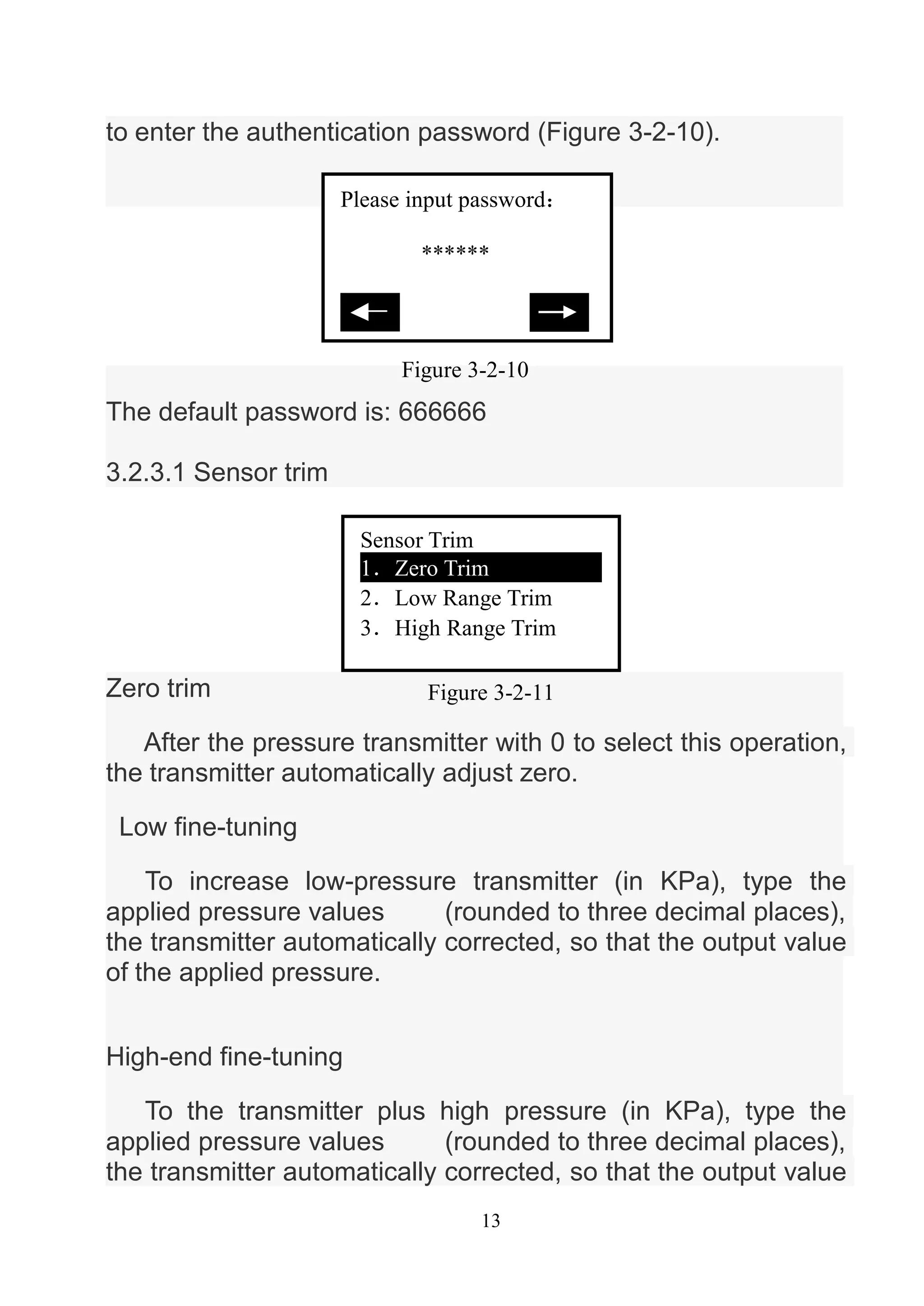
3.2.3.2 Sensor Range
Select the range
First select the type of sensor, and then select the range of
the sensor code, then press the Enter key into the transmitter.
(Figure 3-2-13,3-2-14)
Modify Range
First select the range sensor code, then enter the code in
the range of the scale. Note: The input pressure is measured in
Pa, can only enter a positive integer. Change and then select
the sensor range.
3.2.3.3 User range
Keyboard input
Figure 3-2-12
Sensor Range
1.Select the range
2.Madify range
Figure 3-2-13
Sensor type
[ DP ]
推出
Figure 3-2-14
Range Code
[5]
推出](https://image.slidesharecdn.com/hart475-210310004633/75/Hart-475-14-2048.jpg)


![17
Interpolation
After the ultra-poor calibration point format.
Note: This action will seriously affect the accuracy of the
transmitter, the user is best not to make their own format.
How-to: give added pressure transmitter, and then enter the
increase of pressure. (Note: do the formatting in the negative
pressure side, the input pressure to a minus sign in front).
Press the right navigation key, the interpolation done at this
time point measured the pressure should be basically equal to
the applied pressure.
3.2.3.6 Small-signal removal
This function is to eliminate the zero drift. Enter the
number of users than the extreme range.
3.2.3.7 Device address
View a device's address. Device address is the unique
identification number the smart board.
3.2.3.8 Data Backup
Data backup: the value of the current user scale and
format all the data back to FLASH the database, this function is
All of range:01
PRESS:[ ]Pa
Figure 3-2-19
Interpolation
PRESS:[ ]Pa
Figure 3-2-20](https://image.slidesharecdn.com/hart475-210310004633/75/Hart-475-17-2048.jpg)


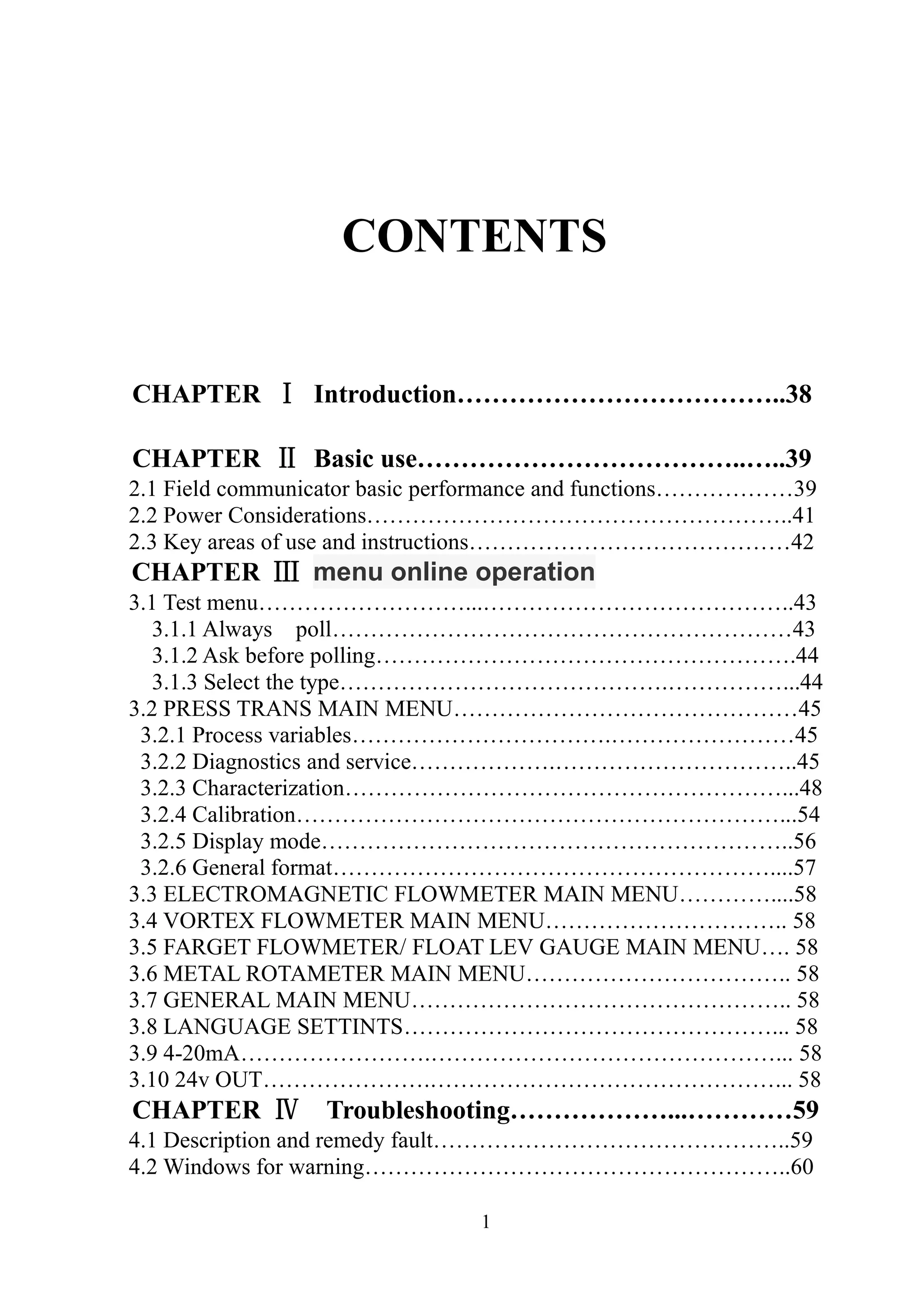
The document is a manual for the HART 475 Field Communicator, detailing its introduction, basic operational features, menu navigation, and troubleshooting steps. It covers the device's performance, power requirements, key functionalities, and specific procedures for using various types of measurement instruments such as pressure transmitters and flowmeters. The manual emphasizes the importance of understanding the device's operations for optimal performance and provides guidance on troubleshooting common issues.
This section outlines the contents of the manual, introducing chapters on basic use, menu operations, troubleshooting, and appendices.
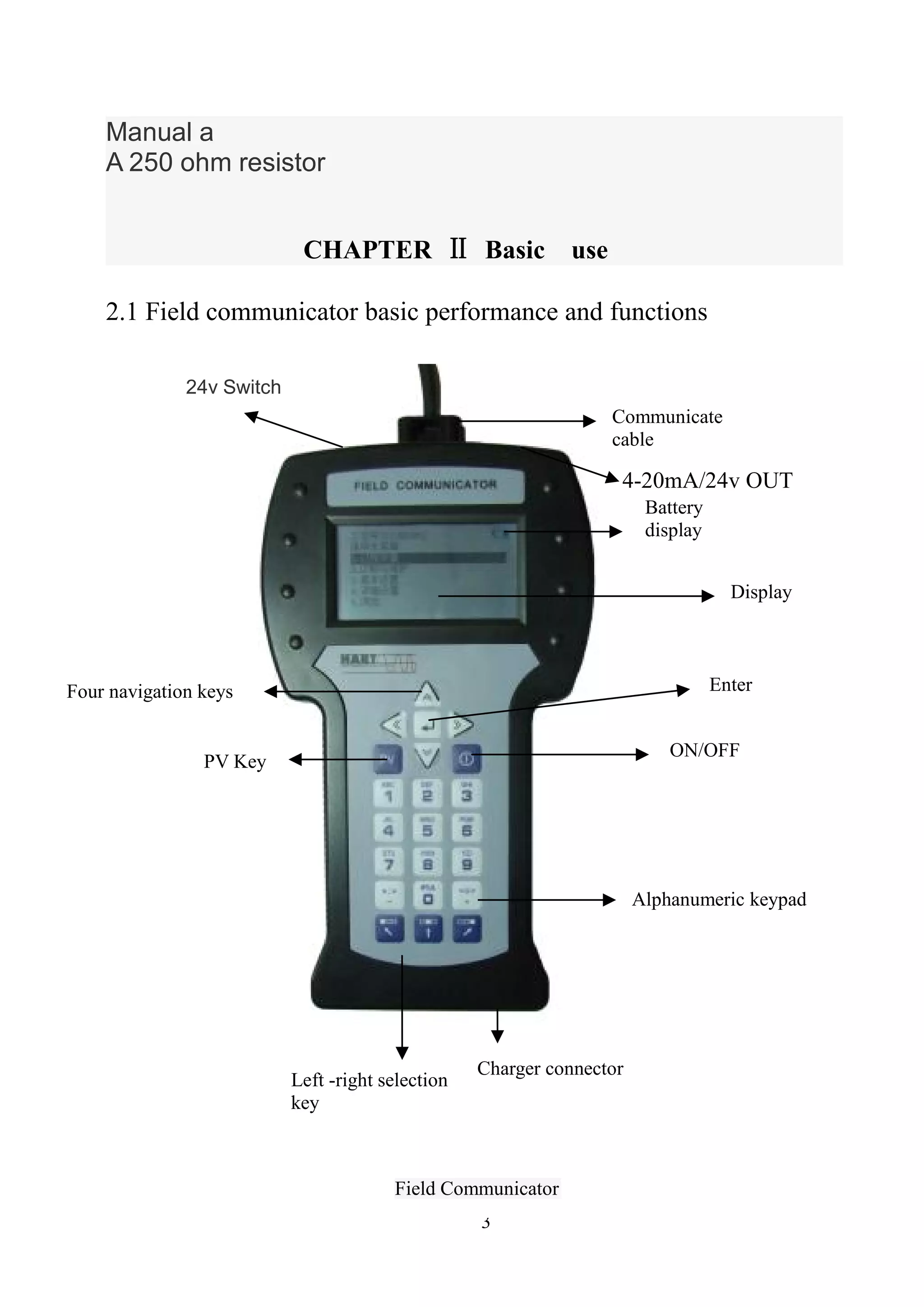
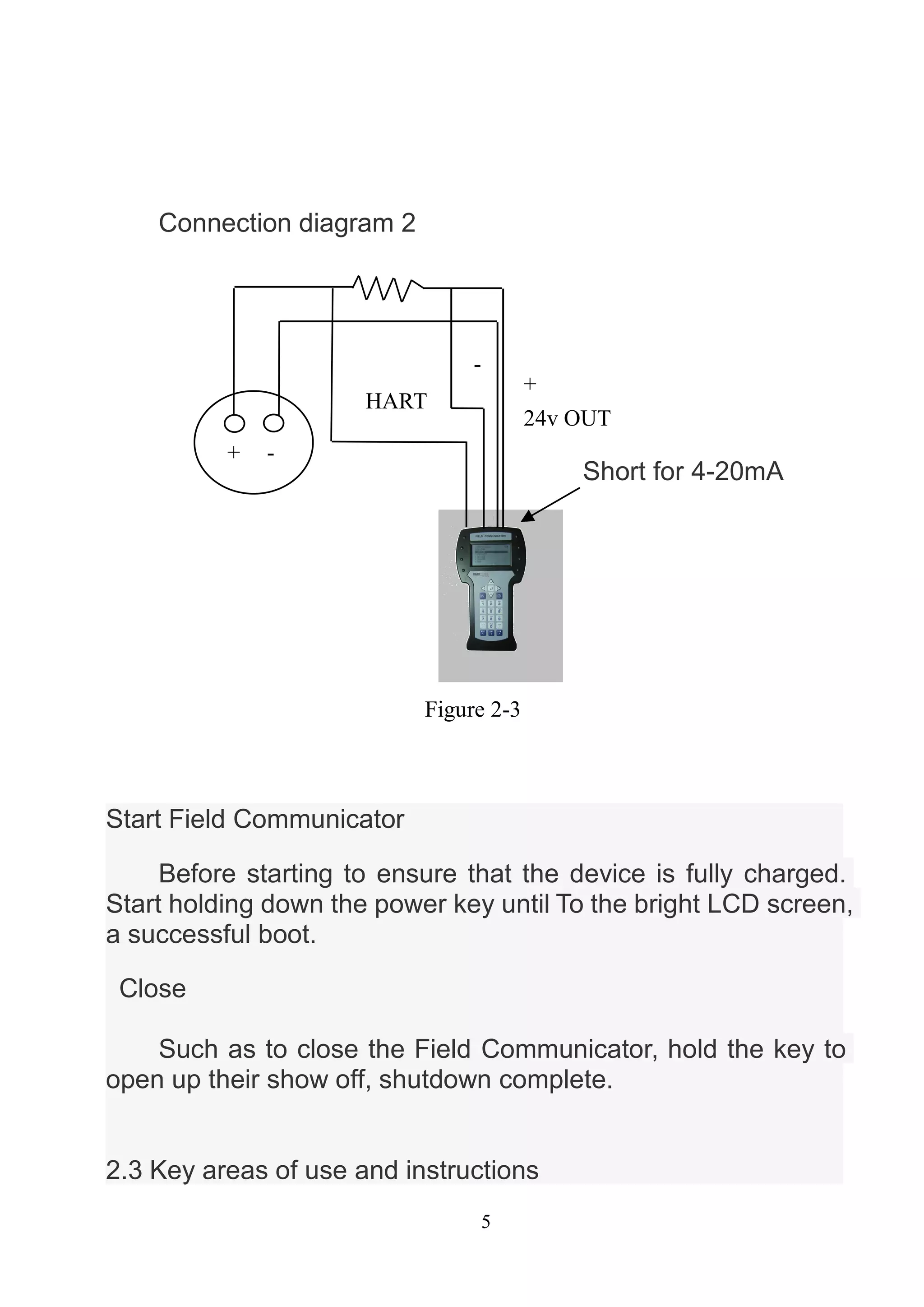
Details the basic performance and functions of the Field Communicator, including power requirements and operational controls.
Describes detection menus and how the Field Communicator polls devices, allowing for selection and type detection.
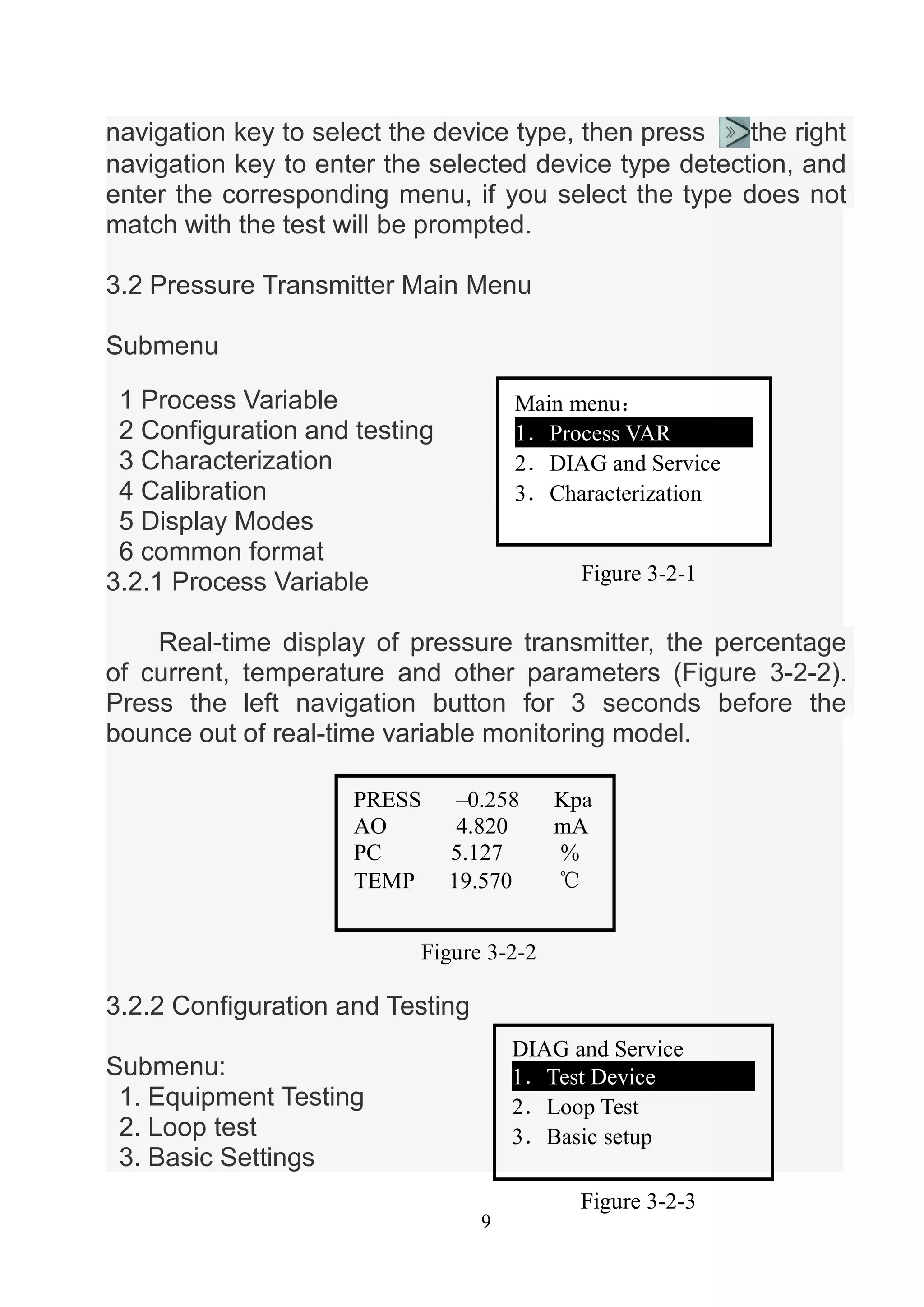
Details functionalities in the Pressure Transmitter Main Menu, including process variables, characterizations, and calibration options.
Focuses on varying configurations for sensor trimming, including zero and high-range fine-tuning, and calibration processes.
Outlines different display modes for pressure transmitters and general formatting requiring security access for accuracy.
Details main menu trees for various flowmeters, including language settings and calibration options common to devices.
Provides troubleshooting information on device connectivity issues, low battery warnings, and common input errors.
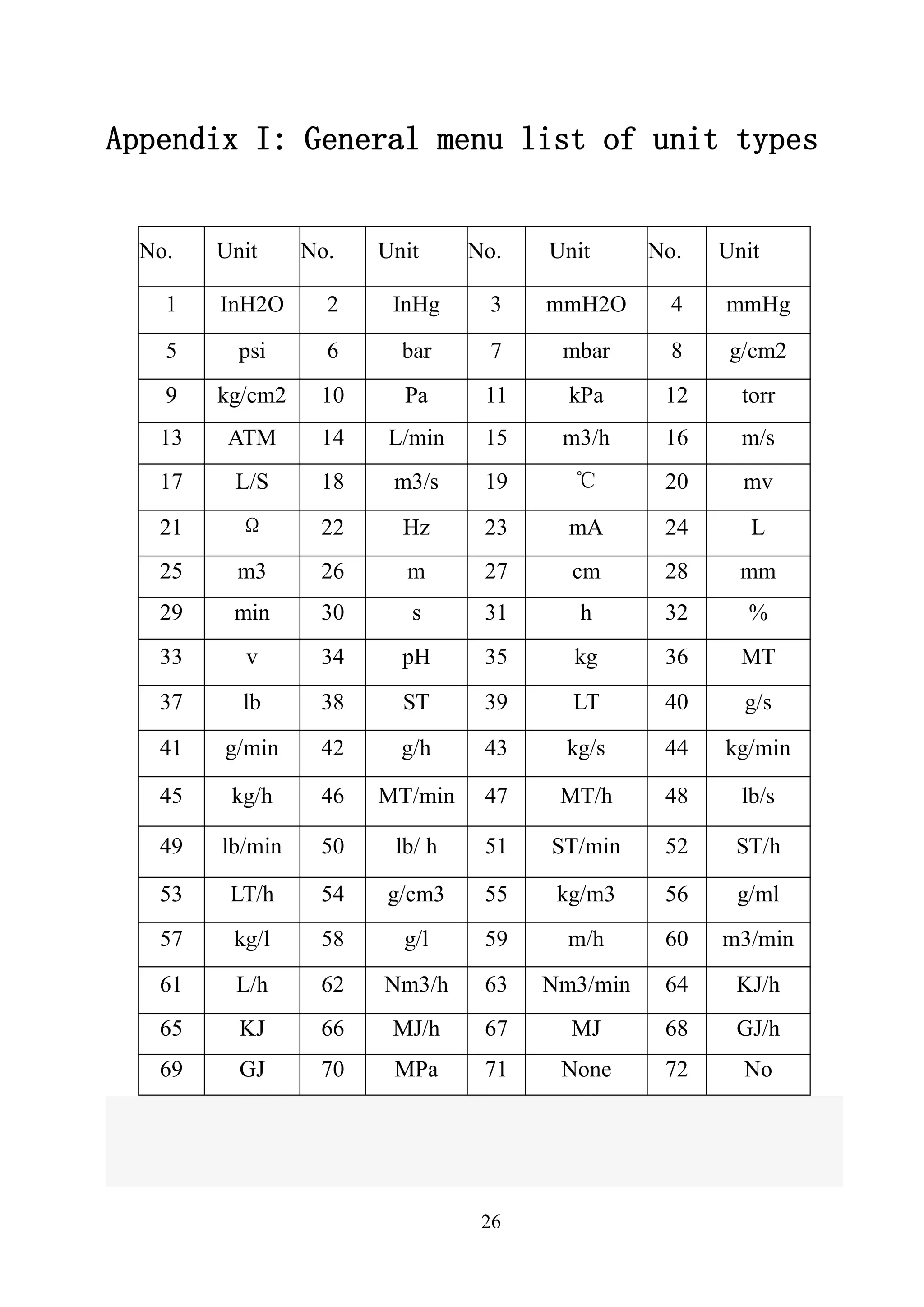
Includes a list of unit types, equipment menu tree, and glossary of terms relevant to HART communication devices.
Details main menu trees for various flowmeters, including language settings and calibration options common to devices.
Includes a list of unit types, equipment menu tree, and glossary of terms relevant to HART communication devices.


