This document is the user's manual for the 475 Field Communicator. It provides instructions on operating the device safely and gives an overview of its features. These include communicating with HART and fieldbus devices, managing device configurations, battery and accessory information, and troubleshooting. The manual contains sections covering basics, HART and fieldbus functionality, maintenance, and specifications.


![94
POWER
SUPPLY/CHARGER
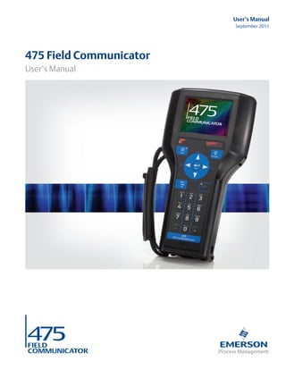
SPECIFICATIONS
Connection Green six-pin mini din (male) plug
Lights The power supply/charger has three colored lights that indicate the
conditions below. Each light displays a different color.
Voltage 100-240 VAC, 50/60Hz,
US/UK/EU connection types included
Technical data
Color Condition
Green The battery is fully charged.
Flashing green The battery is nearly fully charged.
Yellow The battery is charging.
Flashing yellow The power supply/charger is not connected
to the 475 Field Communicator.
Flashing yellow and
red
The remaining charge in the battery is low.
Red Charging cannot occur. Contact Technical
Support for more information.
Input voltage 100 - 240 VAC ±10%
Input current 750 mA max.
Standby current 20 mA max.
Input fuse type TES 2A 250 V Timelag
Output voltage 1 0 - 8.3 V
Output current 1 1000 mA max.
Output voltage 2 0 - 9.0 V
Output current 2 1400 mA max.
Output power rating 20 W
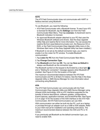
Operating temperature 0°C - +40°C
Storage temperature -20°C -+80°C
Measurements [L x B x H] 112 mm x 51.5 mm x 29.5 mm
Total Mass 240 g.
Altitude Up to 2000m
Pollution Degree 2
Installation Category 2
IEC Protection Class Double Insulation](https://image.slidesharecdn.com/475manual-161114221928/85/475-manual-96-320.jpg)


