SlideShare a Scribd company logo
1 of 39
Download to read offline
1 / 39
Metallurgy and Welding (Preliminary)
I. Metallurgy
• ASTM designates all ferrous alloys by the letter A and non-ferrous alloys by B. ASME
uses the prefixes SA and SB. The ASME material number is usually the same as the
ASTM number except that it is prefixed with an S.
• ASME code materials may be used in applications requiring ASTM materials but not the
reverse. ASTM materials may be of the same composition and properties as ASME
materials but do not have the extensive quality-control requirements assigned to ASME
materials.
• Unalloyed steels are divided into:
i. Plain carbon steel (mean Mn content < 1%)
ii. High manganese carbon steels (mean Mn content ≥ 1%).
• Plain Carbon Steels
i. Low-carbon steel (0.15% C max.) – excellent weldability.
ii. Mild steel (0.15 – 0.3% C) – good weldability.
iii. Medium carbon steel(0.3 – 0.5% C) – fair weldability (preheat & postheat required)
iv. High carbon steel (0.5 – 1.0% C) – poor weldability (preheat & postheat required)
• Hypo-eutectoid steels have less than 0.8% C and whose structure consists of ferrite and
pearlite.
• Eutectoid steel has 0.8% C and the microstructure is 100% pearlite.
• Hyper-eutectoid steels have greater than 0.8% C and the microstructure consists of
pearlite plus massive cementite.
• Mild steel is an alloy of iron and less than 0.25% C, and about 0.7% Mn. Mild steel is
generally used in the normalized condition.
• Cast irons typically have over 2 % C plus 1 – 3 % Si and are difficult to weld. They are
fully-killed (> 1% Si). Cast iron has good corrosion resistance to mild caustic and cold
non-corrosive solutions. Among all types cast iron, grey cast iron is the most widely
used type.
• Cast steel is often required in refinery or high pressure service (i.e. API pumps). If the
product is flammable or toxic, cast steel is preferred because it is more resistant to
fracture when sprayed withwater during a fire.
• Concentrated (80 %) H2SO4 acids are routinely handled by cast iron and steel, provided
velocities are below 0.7 m/s for steel and below 1.5 m/s for cast iron, whose protective
iron sulfate film is more tenacious. Ductile cast iron is much to be preferred for safety
reasons.
2 / 39
• Carbon steel with 0.4% C is used for bolts, studs and nuts.
• Alloy steels are sub-divided into:
i. Low-alloy steels (total alloy content < 5 %)
ii. High alloy steels (total alloy content > 5 % )
• Different metallurgical phases in steel:
i. Ferrite
High strength and tough.
Brittle at low temperature.
Provides resistance to stress-corrosion cracking.
Low solubility for hydrogen; hydrogen diffuses easily in ferrite.
ii. Austenite
Corrosion-resistant .
Ductile even at low temperature.
Susceptible to stress-corrosion-cracking.
High solubility for hydrogen; hydrogen diffuses slowly in austenite.
iii. Pearlite
Formed on slow-cooling of mild steel (0.18 – 0.35% C).
iv. Martensite (meta-stable phase)
Formed on rapid-cooling of mild steel.
Needlelike (acicular) structure.
Harder and less ductile than pearlite.
v. Bainite (meta-stable phase).
Even more rapid cooling than is required to produce martensite.
Needlelike (acicular) structure.
Harder and less ductile than pearlite.
• Factors that affect cooling rates:
i. Total heat input, including preheating.
ii. Material size and thickness.
iii. Thermal conductivity of material.
• Heat input =
minute)per(cmspeedtravel
minute)per(cmspeedx travel60xx voltageamperage
(J/cm)
• Heat input in SMAW is regulated by both current flow and electrode manipulation.
• Faster cooling rate increase the likelihood of martensite and bainite formation.
• For the welding of hardenable steels, it is important to determine the critical cooling rate
(CCR) that the base metal can tolerate without cracking.
3 / 39
• Ferritic steels are characterized by an abrupt decrease in fracture energy with decreasing
temperature. This is associated with a transition from a fibrous to a cleavage mode of
failure.
• Austenitic steels are recommended for cryogenic applications as they exhibit no impact
transition temperature and possess high fibrous fracture energy.
• For ferrite-pearlite (i.e. normalized) carbon steels, the impact transition temperature
increases and upper shelf energy decreases with increased carbon content.
• Impact transition temperatures decreases markedly with decreasing grain size.
• Grain size has no effect on upper shelf energy
• In the austenitic range (1390o
C) grains can increase in size. The higher the temperature
above A3 and the longer the holding time, the larger the grain size.
• Roles of alloying elements in steel:
i. Carbon
a. Has higher solubility in austenite than ferrite. In ferrite, solubility is very low
so that C exists in steels as iron carbides (Fe3C).
b. Austenite stabilizer.
c. Strength and hardenability increase whenC content increases.
d. Ductility, toughness, weldability, workability, and machinability are reduced
when C content increases.
e. In ferrite-pearlite (i.e. normalized) steels, increasing C increases Impact
Transition Temperature (ITT) dramatically.
f. In hardened and tempered steels, increasing C content increases ITT and
decrease upper shelf energy. Effect is less pronounced than in ferrite steels
and is dominated by effect of C on strength.
ii. Mn
a. Austenite stabilizer.
b. Does not form carbide.
c. Combines with S impurities to form particles of MnS, thereby avoiding the
possibility of the formation of the detrimental FeS phase (FeS is brittle, and
they melt at low temperatures causing the steel to be hot short).
d. Contributes to strength by solution strengthening the ferrite and refining the
pearlite.
e. When Mn > 0.8 %, it strongly increases hardenability.
f. When Mn > 2 %, it severely embrittle steel.
g. Increases susceptibility to temper embrittlement and quench cracking.
h. In ferrite-pearlite steels, up to 1.5% Mn lowers transition temperature at a rate
of approximately 5o
C per 0.1% Mn due to the refinement of pearlite and
reduction in grain size.
i. In hardened and tempered steels Mn increases hardenability and hence
increases toughness of large sections by ensuring a fully martensitic structure.
j. High concentration of Mn can aggravate temper embrittlement problem that
is caused by the presence of P, As, Sn and Sb.
4 / 39
iii. S
a. Deleterious impurity in steels.
b. Combines with steel to form FeS - brittle and has low melting point. FeS
causes cracking during both cold and hot working.
c. Segregates in steel castings and ingots, and degrades surface quality.
d. Intentional addition of S is made to improve machinability.
e. Toughness reduces with increased S content.
f. It makes steel brittle at high temperature (i.e. hot-short).
g. In amounts exceeding 0.05% it tends to cause brittleness and reduce
weldability.
iv. P
a. Segregates in steel castings and ingots, and forms a brittle FeP phase that
reduces toughness.
b. Phosphorous segregation during heat treatment is responsible for temper
embrittlement.
c. Hardener of steel.
d. It makes steel brittle at low temperature (i.e cold-short).
e. It tends to cause brittleness when present in excess of 0.04%.
v. Al
a. Used for deoxidation.
b. Control of grain size.
c. Control austenite grain growth in reheated steels.
d. Up to 0.1% lowers impact transition temperature (ITT) due to grain
refinement and removal of dissolved nitrogen.
e. Toughness improved by reduction in oxygen content.
f. High levels of Al increase ITT.
vi. Si
a. Ferrite stabilizer.
b. A deoxidizer commonly used in killed steels.
c. In cast irons, Si promotes graphite formation and provides resistance to attack
by corrosive acids.
d. In low concentrations (0.15 – 0.3%) improves toughness by lowering O2
content. Higher levels tend to raise Impact Transition Temperature (ITT).
e. Increases the susceptibility to temper embrittlement.
vii. Cr
a. Strong ferrite stabilizer
b. Strong carbide former.
c. Provides solution strengthening of ferrite.
d. Increases hardenability on medium C steel.
e. Increases toughness of hardened and tempered steels in large sections due to
increased hardenability.
viii. Ni
a. Austenite stabilizer.
b. Does not form carbide.
c. Increases hardenability in medium C steel.
d. Increases notch toughness.
5 / 39
e. Often used together with Cr in alloy steels to provide high hardenability, high
impact strength, and improved fatigue resistance.
f. Increased Ni, along with N, enhances the chloride stress-corrosion-cracking
(SCC) resistance.
g. Increased Ni lowers transition temperature progressively. With greater than
9% Ni transition temperature is decreased to around -150o
C.
ix. N
a. Improves localized corrosion resistance, mechanical properties, and thermal
stability.
b. N, along with Ni, enhances the chloride stress-corrosion-cracking (SCC)
resistance.
x. Mo
a. Ferrite stabilizer.
b. Strong carbide former.
c. Contributes to solution strengthening of ferrite.
d. Acts as a grain refiner.
e. Reduce susceptibility to temper embrittlement in alloy steels.
f. Improve resistance to pitting corrosion(i.e. localized corrosion).
g. Increases resistance to temper embrittlement in hardened and tempered steels.
h. Addition of Mo in concentrations up to 0.7% can alleviate temper
embrittlement problem caused by high concentration of Mn.
i. Increases hardenability.
xi. V
a. Stronger carbide former than Cr or Mo.
b. Promotes grain refinement.
c. Decreases impact transition temperature in H.S.L.A. alloys due to grain
refinement.
d. Contributes to secondary hardening during tempering.
e. Used primarily in creep resistant steels.
• Steels with higher strengths and higher alloy contents are more susceptible to hydrogen-
related cracking. This explains why major oil companies prohibit SA516 Gr. 70 to be
used in pressure vessel construction.
• For plate steels, the lower strength materials (Grade 55 or 60) are preferred. Lower
strength materials are less susceptible to sulfide stress corrosion cracking (SCC).
• Classifications of Steels (based on deoxidation practice):
i. Fully Killed Steels
a. Fully deoxidized steels (with addition of Si or Al).
b. Si is the deoxidizer most often used, and more thorough deoxidationcan
be accomplished by adding stronger agents, such as Al, Ti, or Ca-Sialloy.
c. Alloyed steels and carbon steel with C content greater than 0.4 % are
always killed.
d. 0.25 % < Si < 1.0 %
e. Characterized by minimum chemical segregation and uniform mechanical
properties, thus can be used in low temperature vessel.
6 / 39
f. Most expensive to produce.
g. Specified when a homogeneous structure and internal soundness are
required, or when improved low temperature impact properties are
desired.
h. For service temperature above 454 o
C, it is recommended that killed steels
containing ≥ 0.1% residual Si be used.
i. They are used for thicker pressure vessels (i.e. > 1 in) or, in all
thicknesses, for more severe duty.
j. In the context of API 650, a fully-killed steel is an Al killed steel.
ii. Semi-killed Steels
a. Partially deoxidized steels – a compromise betw. Rimmed and fully-killed
steels.
b. Semi-killed steels are Si deoxidized, and the grain structure is larger.
c. 0.15 % < C < 0.3 %
d. 0.05 – 0.1 % Si
e. Grain sizes are not controlled.
f. Most economical to produce.
g. Used extensively for structural applications.
h. Almost all the plate used in pressure vessels up to 1.0 in thick for light
duty service is semi-killed.
iii. Rimmed Steels
a. Have not been treated for oxygen removal.
b. C < 0.25 % and Mn < 0.25 %
c. Si < 0.05 %
d. Characterized by a pronounced lack of chemical homogeneity
e. Has a skin of very pure ferrite (the surface is very smooth), almost free from
both cementite and slag particles. It is more favorable from the corrosion
point of view, since particles of cementite form local cells, while all slag
particles jeopardize the formation of passivating oxide films and the adhesion
of protective coatings..
f. More expensive than semi-killed steels due to careful control required of the
slag composition, pouring temperature, O2 level and other variables.
g. It is commonly used to manufacture mild-steel and low-alloy SMAW
electrodes (core wire).
Note: During welding, the O2 present in rimmed steel combines with C in the weld
puddle to for CO. Porosity in weld metal may result from excessive CO
remaining in the weld pool upon solidification. Killed steels are less prone to
CO porosity.
Rimmed Semi-killed Fully-killed
C content (%) Up to 0.3 % Up to 1.0 % Up to 1.5 %
Si content (%) < 0.0005 % 0.01 < Si < 0.1 % > 0.1 %
Primary Piping (shrinkage) None None Severe
Porosity in ingots Considerable Some None
Segration Pronounced Little Very Little
• Steel plates that require hydrogen induced cracking (HIC) resistant properties must be
fully-killed.
7 / 39
• The selection of a design metal temperature is the first and most important step in
ensuring that materials are selected which are tough enough to prevent brittle fracture
under the service conditions.
• The Minimum Design Metal Temperature (MDMT) is the lowest temperature expected
in service at which a specified design pressure may be applied. Unless the combination
of material and thickness used is exempt by the curves of UCS-66 at the MDMT (i.e.
below the respective curve), impact testing of the material is required, and the PQR
would also have to include impact testing of welds and HAZ.
• Creep is a phenomenon at elevated temperature where strain is dependent of time under a
constant applied load.
• Creep range:
i. About 371o
C for carbon and low alloy steels.
ii. About 427o
C for high alloy steels
Note: a. Increasing alloy content raises the temp. at which creep begins.
b. Upon prolonged exposure to temperatures above 427o
C, the carbide phase of
carbon steel may be converted to graphite.
• Superheater tubes, superheater outlet headers, and main steam piping typically operate in
the creep range.
• One way to assess creep damage is to apply the linear-damage rule (a.k.a. Robinson’s
rule). As for fatigue, Miner’s rule is used to assess fatigue damage.
• At elevated temperature, fatigue damage is more severe than at room temperature.
• Creep-fatigue interaction:
Fatigue damage is additive to creep damage, and the two damage mechanisms interact to
accelerate the expenditure of component life at elevated temp.
• Components in elevated-temperature service are more susceptible to fatigue damage.
• There is a pitfall to be avoided when selecting welding electrodes and filler metal for
pressure retaining welds in 2¼ Cr-1Mo materials for service at design temp exceeding
850o
F. Namely, the weld metal must have a carbon content greater than 0.05% , except
for circumferential buttwelds no larger than 3½ inches in O.D.. This min. carbon content
is thought to be needed to maintain the elevated temperature strength of the weld metal.
• At temperatures below the creep range, the allowable stress for a material stated in B31.3
(Table A-1, Appendix A) is the lowest of the following conditions:
Primary
Creep
Secondary
Creep
Tertiary
Creep
Time
Strain
8 / 39
i. 1/3 of the specified min. tensile strength at room temp.
ii. 1/3 of the tensile strength at design temp.
iii. 2/3 of the specified min. yield strength at room temp.
iv. 2/3 of the yield strengthat design temp. For austenitic stainless steels, this value
may be as large as 90 % of the yield strength at design temperature.
Note: The use of design stresses relatively closer to the yield strength of austenitic
stainless steels can be justified by the fact that these alloys work hardenon
yielding and also that they have a very large margin between yield strength and
UTS (i.e. they are very ductile).
• For most Sect I materials the allowable stress at room temperature is actually based on ¼
of the UTS, which is quite a bit lower than2/3 of the yield strength.
• The yield strength (and UTS) of most materials as received from the mill is somewhat
stronger, often by 10 % or more, than the minimum called for by the material
specification, although no credit may be taken for this extra strength.
• At temperatures in the creep range, the allowable stress of a material is the lowest of the
following conditions:
i. Average stress to produce a secondary creep rate of 0.01% per 1000 hrs.
ii. 67% of average stress to cause rupture in 100, 000 hrs.
iii. 80% of min. stress to cause rupture in 100, 000 hrs.
• For API 650, the allowable stress (a.k.a max. allowable product design stress) is the
lower of the following conditions:
i. 2/3 of the yield strength
ii. 2/5 of the tensile strength
• Selection of steels for fatigue resistance.
i. Fatigue strength of homogenous structures is generally superior to that of mixed
structures.
ii. Even small amounts of bainite or ferrite and pearlite will produce a reduction of
about 20% in fatigue limit.
iii. Ferrite-pearlite steels have inferior fatigue strength to martensitic steels of the same
strength.
iv. Fatigue strength of high C pearlite structures can be improved by spheroidization.
v. Any compositional modifications which result in increased tensile strength
simultaneously increase the fatigue strength.
vi. Fatigue properties of high strength steels are extremely sensitive to surface finish.
vii. Heat treatment processes which increases tensile strength generally also increase
fatigue strength.
• Selection of steels for toughness.
i. Fibrous fractures are usually tough and resist rapid crack propagation.
ii. Cleavage fractures are associated with a low energy of propagation and usually
result in catastrophic brittle fracture.
iii. Toughness is characterized by the fibrous fracture energy, the impact energy at
service temperature and the nil-ductility-transition (NDT) temperature.
• Commonly used P-number categories:
9 / 39
i. P-1 Plain carbon steels, C-Mn-Si, C-Mn, and C-Si steels.
ii. P-3 Low alloy steels obtained by additions of up to ¾ % of Mn, Ni,
Mo, or Cr, or combinations of these elements.
iii. P-4 Low alloy steels with higher additions of Cr or Mo or some Ni, to
a max. of 2% Cr., ½ % Mo.
iv. P-5 Covers a broad range of alloys varying from 2.25 Cr-1Mo to 9 Cr-
1Mo.
5A Up to 3% Cr, ½ - 1% Mo.
5B 3 – 9 % Cr, 1 % Mo.
5C Strength has been improved by heat treatment (85 ksi or
higher).
v. P-7 Ferritic stainless steels (seldom used piping material)
vi. P-8 Austenitic stainless steels (i.e. 200 and 300 series).
vii. P-10H Duplex stainless steels.
viii. P-10I,J,K Ferritic stainless steels.
ix. P-11 Heat treated low and intermediate alloy steels.
x. P-44 Nickel-base alloy (e.g. Hastelloy)
xi. P-45 Nickel-base alloy (e.g. solution-annealed Incoloy)
Note: Alloys of P-5 and higher groupings require protection from oxidationduring
welding, which is often accomplished by purging the inside of the pipe with Ar or
N. P-10 materials are commonly used in low-temperature applications.
• Clean surfaces are important in TIG welding because the process does not include a flux
to float off impurities.
• When Al or Ti is welded, the surfaces and filler metal often must be treated chemically
to remove oxides.
• Section IX does not establish when notch-toughness tests are required. Notch-toughness
requirements are established by the construction specifications by specifying impact test
requirements.
• Sect VIII Div 1 Part UHT requires impact testing for the ferritic materials with properties
enhanced by heat treatment.
• A material notch-toughness property may be reduced with an increase in heat input.
• Two ways to ensure that a selected steel has adequate toughness for the design metal
temperature:
CharpyV-notchImpact
energy,CVN(J)
Temp (o
C)-50 0
0.2 % C
0.41 % C
Upper shelf energy
Lower shelf energy Impact Transition Temp
Nil Ductility Temp.
0.31 % C
0.11 % C
10 / 39
i. Impact toughness testing of samples at or below design metal temperature
(MDMT).
ii. Select a material whose impact transition temperature is below the design metal
temperature, so that impact testing is not required.
Note: 1. Method (ii) is generally preferred as impact testing adds a premium of about
10% to the cost of the plate.
• Factors affecting notch toughness:
i. Temperature
ii. Grain size
iii. Deoxidation
iv. Carbon content
Carbon increases the transition temperature and decreases the fracture energy.
Carbon content should be kept low.
v. Heat treatment
Normalized or quenched and tempered steels have lower transition temperature
than as-rolled plates.
vi. Heat input
Higher transition temperature in the HAZ compared to the base material. Notch
toughness may be reduced with increase in heat input.
vii. Thickness
For a given material the fracture toughness decreases with increasing thickness.
Brittle fracture has not occurred in tanks with shell plates less than ½” thick. Any
tank that uses ½” thick or less plate for its shell is exempted from brittle fracture
concerns.
• Factors that increase heat input:
i. A higher welding heat input.
ii. A higher maximum interpass temperature.
iii. A longer PWHT time.
iv. A reduction in base metal thickness (i.e. slower heat dissipation).
v. A change to uphill progression in vertical welding.
vi. A change from stringer bead to weave bead welding.
vii. The location in a pipe where the test specimen is removed. The heat input varied
in a pipe welded in the 5G and 6G positions; the upper portion of the pipe
receives more heat input than that of the lower portion because heat rises. As
such, QW-463.1(f), Sect IX mandates that the test specimen of pipe welded in
5G and 6G positions shall be removed only from specified portions of the pipe..
• For non-notch-toughness applications, the Code requires the UTS and ductility properties
of a PQR test coupon to be established. For notch-toughness applications, the notch-
toughness properties of a PQR test coupon are to be established, in addition to the non-
notch-toughness properties.
• Notch-toughness requirements are mandatory for all P-11 quenched and tempered metals.
11 / 39
• Supplemental essential variable becomes an essential variable only if notch toughness
testing is required.
• As ASME Section I vessels are usually quite warm when pressurized, Sect. I does not
require notch toughness, or impact testing, and supplemental essential variables are not
used in welding for Sect I construction.
• P-Number groupings:
i. To reduce the no. of WPS required, P-numbers are assigned to base metals
depending on characteristics such as composition, weldability, and mechanical
properties.
ii. The same P-number groups the various base metals having comparable
characteristics.
iii. Groups within P numbers are assigned for ferrous metals for the purpose of
procedure qualifications where notch toughness requirements are specified.
iv. If a P number is not available for the material involved, its ASTM specification
number may be used. If an ASTM specification number is not available, the
chemical analysis and mechanical properties can be used.
v. Group numbers subclassify the base metals within P-numbers for the purpose of
procedure qualification where notch-toughness requirements are specified by the
construction code.
• S-Number groupings:
i. The use of S-Number is not mandatory.
ii. PQR of a base metal in one P-Number qualifies that procedure for all other base
metals in the same S-Number, but not vice versa.
iii. Performance qualification with P-Numbers qualifies a welder for the
corresponding S-Number, and vice versa.
• F-Number groupings:
i. To reduce the number of PQR and WPQR.
ii. Welding filler metals are categorized based on their usability characteristics,
which determine the ability of welders to make satisfactory welds.
iii. Welder qualification with a filler metal that is more difficult to use qualifies a
welder to use a filler metal that is easier to use.
iv. The ASME specification numbers are the same as the AWS specification
numbers with the addition of the letter SE.
• A-Number groupings:
i. Weld metal composition is categorized into different A-Number groupings.
ii. A-Number is used for the classification of ferrous weld metal for procedure
qualification.
iii. A-Number can be an essential variable for the WPS.
iv. A-Number is not an essential variable for welder performance qualification.
• OFW may be used only if the following conditions are satisfied:
i. Small-bore steel piping (i.e. < 2”)
ii. Base material is either C or C-Mn steel.
iii. Base material thickness < 5 mm.
iv. Tensile strength of material < 66 ksi.
12 / 39
• GMAW is commonly used in fabrication shops. GMAW may be used for all-position
root- and cover-pass welding, up to a maximum current of about 250 amps. With higher
currents, welding is restricted to the downhand position, in which case the wires are
often composites.
The following are are-welding processes:
i. SMAW (slag shielded)
ii. GTAW (TIG or PAW) (gas shielded)
iii. GMAW (MIG) (gas shielded) – deep penetration
iv. FCAW (slag shielded) – deep penetration
v. SAW (slag shielded) – deep penetration
GMAW (which includes MIG) always use a continuous electrode wire, thus they can
produce more kgs of weld metal per hour.
Characteristics SMAW GTAW GMAW FCAW SAW
Weld quality Good Excellent Excellent Good Excellent
Weld disposition rate Fair Poor Good Good Excellent
Field work Excellent Poor Fair Excellent Poor
Equipment maintenance Low Low Medium Medium Medium
Fume emission High Low Medium High Very low
Arc visibility and filler-
metal placement
Good Excellent Satisfactory Satisfactory Poor
Variety of metals weldable Excellent Excellent Good Good Fair
• The conditions that determine the electrical power specifications for arc welding are the
thickness of base metal, procedure position, and the specified electrodes.
• Joint Preparation for TIG:
i. Butt joint shapes
a. Single-V
The amount of root opening and the thickness of the root face or land depends
upon whether the TIG process is to be manual or automatic, whether the filler
metal is to be added during the root pass, and whether a backing strip is to be
used.
b. Double-V
Ø Used when thicker sections require complete joint penetration and a
single-V butt joint would require too big an opening at the top of the V.
Ø Double-V will use less filler metal and cost less to make thicker sections
than a single-V.
c. Single-U
Ø U-joint is quite expensive to make. Also, it requires more filler metaland
more welding labor.
Ø Used on materials such as Ti and Al are extremely fluid when molten, and
they are difficult to weld without internal backing or a consumable insert
in the root gap.
Ø Employed when working on thick pipes where it is only feasible to weld
from one side, (Although a double-V joint to join the thick material from
both sides is preferred.)
ii. Bevel angles
a. Edge beveling is not usually needed for butt joints 3mm (1/8”) or less in
thickness in C.S., low-alloy steels, stainless steels, and Al.
b. For high-Ni alloys, beveling is not needed for material 2.4 mm (3/32”) thick or
less.
c. For thicknesses greater than condition (a) or (b), the joint should be beveled to
form a V, U or J groove.
d. V-groove joints:
i. 60o
groove for carbon, low-alloy, and stainless steels.
ii. 80o
groove for high-nickelalloys.
iii. 90o
groove for welding Al with a.c. TIG.
e. U-groove joints:
i. 7 – 9 o
sidewall bevel for carbon, low-alloy, and stainless steels.
ii. 15o
sidewall bevel for high-Ni alloys.
iii. 20 – 30o
sidewall bevel for welding Al.
f. Single-bevel T joints (between dissimilar thicknesses):
i. 45o
groove for carbon, low-alloy, and stainless steels.
ii. 60o
groove for welding Al alloys.
g. A double-V or double-U joint is preferred for material over 12 mm (1/2 “) thick.
The added cost of preparation is justified by the decreased amount of weld metal
and lower welding time needed to complete the joint. In addition, less residual
stress will be developed than with the single-groove joint designs.
Note: Ni-base filler metals require larger groove angle to allow for the manipulation
of the sluggish weld pool.
• TIG welding process:
i. TIG and GTAW are the same processes and the abbreviations are used
interchangeably.
ii. Scratch starting should not be used.
iii. It can weld just about any metal, even cast irons.
iv. It requires continuous weld-metal shielding with moderately expensive
inert gases.
v. Backup inert-gas shielding in the opposite side of the weld is needed in
some applications, especially when welding Ti, and often when working
on thin sections of easily oxidized metals.
vi. TIG and MIG welding are the only methods for joining Ti and Al.
vii. TIG is most often chosen for root-pass welding of alloy, or otherwise
critical piping that call for a smooth root-pass to reduce stress
concentration.
viii. TIG is widely used for welding stainless steels, especially for full-
penetration welds in thin-gage materials and root passes in thicker
materials.
ix. TIG welding is generally recommended for root passes in one-sided
welding ofduplex stainless steels.
x. In TIG welding of fully austenitic stainless steels, it is often advisable to
add filler metal even when it does not appear to be needed. The proper
addition of filler metal can be used to obtain a convexbead shape, which
14 / 39
has better resistance to hot cracking than does the flat or slightly concave
weld shape that often results when no filler metal is added.
• Shielding Gas for TIG
i. Ar or He is used as shielding gas because of their limited solubility in most metals.
Mixtures of Ar and He are used when some balance between the characteristics of
individual gases is desired.
ii. Ar is the most commonly used TIG shielding gas as it provides a lower arc voltage
than He at any given current and arc length. Arc starting in Ar is also easier than in
He.
iii. When welding in the downhand position, lower flow rates are required from Ar to
provide shielding as Ar is a heavy gas.
iv. When welding overhead, higher flowrates are required from Ar since Ar will tend
to sink as it cools.
v. Ar is used for welding lighter sections because it produces less heat and therefore
less base metal distortion with less chance of burn through when welding thinner
material.
vi. Automatic welding setups may include supplemental shielding gas over the weld
area, with leading or trailing gas shields that increase the coverage. Purge times
must be set to allow the weld metal to cool for a longer period before it is exposed
to atmosphere.
vii. Shielding and backing gases have an effect on the N content of the weld metal. A
loss of N can have a negative impact on corrosion resistance of duplex stainless
steels especially in TIG welding.
viii. He or Ar-He mixture are used as shielding gases for heavy sections to achieve
greater heat input or higher welding speeds.
ix. Additions of 5% H2 to Ar gas shielding have been used for austenitic stainless
steels to provide higher heat input and a cleaner weld surface.
x. Drafts, low gas-flow rates, or excessively high gas-flow rates can cause air to enter
the arc, thus enabling N2 pickup in the weld metal. Proper gas-flow rates, typically
0.3 – 0.8 m3
/h, and barriers that prevent moving air from reaching the arc area can
be used to prevent N2 pickup.
• An essential variable for a weld procedure (PQR) is one which, if changed, would affect
the properties of the weldment and thus require requalification of the procedure (i.e.
additional testing and issuance of a new PQR to support the changed WPS).
• A nonessential variable for a weld procedure (PQR) is one that can be changed without
requiring requalification, although it would require a change in the WPS.
• An essential variable for welder performance is one that would affect the ability of a
welder to deposit sound weld metal.
• In general, welders who meet the code requirements for groove welds are also qualified
for fillet welds, but not vice versa.
• Welders who are eligible to weld pipes shall be eligible to weld plates but not vice versa.
• When a welder has not welded with any process for a period of 3 months, all his
qualifications shall expire.
15 / 39
• When the welder has not welded with a particular process for a period of 3 months or
more, his qualifications for that process shall expire; except when the welder is welding
with another process in which case, the period may be extended to 6 months.
• In B31.1, all welds (including tack welds) in boiler external piping require preheat.
• In B31.1, the thickness for consideration of preheat is the greater of the nominal
thicknesses at the weld for the parts to be joined.
• ASME Sect I does not normally mandate preheat.
• Per PW-39 Sect I, all welded pressure parts of power boilers shall be given a PWHT
unless otherwise specifically exempted.
• Materials for which PWHT is neither required nor prohibited:
i. P-8 (austenitic stainless steels)
ii. P-45 (nickel and nickel-based alloys)
• For P-10 Gp 1 material (ferritic stainless steels), PWHT is always required.
• Difference between ASME Sect I and B31.1 with regards to PWHT:
Sect I requires the PWHT of a small pipe connection to another pipe or header,
while B31.1 often does not.
• Items to be recorded in the WPS:
i. Base Metals
a. The P-No. must be indicated. If a P number is not available for the material
involved, its ASTM specification number may be used. If an ASTM
specification number is not available, the chemical analysis and mechanical
properties can be used
b. The thickness range must be shown, and if it is of pipe, the pipe diameter
range must be shown. This is because base metal thickness influences cooling
rate and, therefore, metallurgical and mechanical properties. Also, the
composition of a metal may also change with thickness.
c. Very thick sections provide a 3-direction heat dissipation while thinner
sections only provide a 2-directional heat dissipation. The thinner sections,
with the slower heat dissipation with the resultant longer time at the higher
temperature, may be more prone to deterioration of the notch-toughness
properties than are the thicker sections.
d. The maximum heat input must be limited on certain types of materials, such
as heat-treated materials that have been quenched, tempered, age hardened, as
well as other heat-treated or cold-worked materials. High heat input processes
are unsuitable for these applications.
e. Qualification in pipe also qualifies for plate welding and vice versa.
f. ASME code permits the qualification on one thickness of test specimen to
cover a range of base metal thicknesses.
ii. Filler Metals
16 / 39
a. The ASME SFA specification number of the filler metal shall be specified.
b. The AWS classification number of the filler metal shall be specified..
c. The filler metal must be produced to an ASME SFA specification, and within that
specification it must be produced to an AWS classification.
d. The addition or deletion of a consumable insert is an essential variable.
e. The size of the filler metal (i.e. diameter) used.
f. Deposited weld metal thickness range for groove or fillet welds.
g. For submerged arc welding (SMAW), the electrode flux class and the flux trade
name must be shown.
h. For gas tungsten arc welding (TIG), the consumable insert analysis should be
shown.
iii. Positions
a. The welding position of the groove or fillet weld must be described.
b. For vertical welding, it should be mentioned whether progression is uphill or
downhill.
c. When notch toughness tests are required, a change from any position to the
vertical uphill progression requires requalification of the WPS.
d. Welding a notch-toughness PQR test coupon in any of the vertical positions, with
an uphill progression, will qualify the WPS for all positions.
e. Unless specifically required otherwise by the welding variable (QW-250), a
qualification in any position qualifies the procedure for all positions.
iv. Preheat
a. Whether or not preheat is required is determined by the carbon equivalent (C.E)
number.
b. The min. temp. shall be given as well as the max. interpass temperature. The
max. interpass temperature shall be controlled to assure it does not exceed the
interpass temperature of the PQR by more than 100 o
F.
c. The interpass temperature must be controlled as the notch toughness properties
could deteriorate with ever increasing interpass temperatures.
d. Preheat maintenance temp should be given.
e. For medium-carbon steels (0.25 – 0.6%) the preheat temperature ranges from 120
– 205 o
C.
f. For high-carbon steels (0.6 – 1.0%) the temperature ranges from 205 – 260o
C,
interpass temperature ranges from 205 – 290o
C.
g. ASME Sect IX permits an increase or decrease of up to 100o
F (56o
C) before
requalification is required.
v. PWHT
a. The use of PWHT, as well as changes in the heat treatment temperature or time at
temperature, will require requalification of PQR.
b. If required, the temperature range and the time at temperature shall be indicated.
c. For medium-carbon steels (0.25 – 0.6%) the temperature ranges from 595 – 620
o
C.
d. For high-carbon steels (0.6 – 1.0%) the temperature ranges from 620 – 650 o
C.
vi. Shielding Gas
17 / 39
a. The use and the composition of a shielding gas are essential variables for arc
welding.
b. It protects the molten metal from atmospheric O2 and N2 as the weld pool is being
formed.
c. It promotes a stable arc and uniform metal transfer.
d. It can affect the weld bead shape and penetration pattern.
e. It interacts with base metals and with filler material to produce the basic strength,
toughness, and corrosion resistance of the weld.
f. In GMAW and FCAW, the gas used has an influence on the form of metal
transfer (e.g. spray transfer, globular transfer, short circuiting transfer) during
welding.
g. In GTAW, typical flow rates for Ar are 7 L/min and 14 L/min for He.
vii. Electrical characteristics
a. Three choices: DCEN, DCEP, a.c.
b. DCEP produces shallowpenetration, wide bead.
c. DCEN produces deep penetration, narrowbead.
d. Alternating current (a.c.) produces medium penetration and bead width.
e. Variations in the type of welding current or in polarity normally require
requalification.
f. A small change in welding current or voltage does not typically require
requalification.
h. Many codes limit changes to ±10% from the mean value, withoug necessitating
requalification.
viii. Technique
a. The WPS shall require requalification if the PQR was welded with stringer beads,
and the WPS will be applied using weave beads.
b. Changing the direction of welding (i.e from downhill to uphill) for vertical arc
welding procedures require requalification of PQR.
c. Changes in mean travel speed of more than 10% require requalification of PQR.
• Shielding/Backing Gases
a. Components of a shielding gas blend:
Argon:
Ø With low ionization potential, Ar promotes easy arc starting and stable arc
operation.
Ø Its low thermal conductivity promotes the development of axial ‘spray’
transfer in certain forms of GMAW.
Helium:
Ø With high ionization potential and thermal conductivity, He transfer more
heat to the base material, thus enhancing the penetration characteristics of
the arc.
Ø It allows higher weld travel speeds to be obtained.
18 / 39
Ø Because of its higher cost, He is frequently combined with Ar or Ar
mixtures to enhance the overall performance of the blend while
minimizing its cost.
Oxygen:
Ø Small amounts of O2 are added to some inert mixtures to improve the
stability of the welding arc developed as well as to increase the fluidity of
the weld puddle.
Ø In the spray transfer mode of GMAW, small additions of O2 enhance the
range
Carbon Dioxide:
Ø It is commonly used alone in certain types of GMAW.
Ø It is added to Ar blends to improve arc stability, enhance penetration, and
improve weld puddle flow characteristics.
Ø The higher thermal conductivity of CO2- transfers more heat to the base
material than does Ar alone.
Hydrogen:
Ø It is added to inert gases to increase the heat input to the base material or
for operations involving cutting and gouging.
Ø Because some materials are especially sensitive to hydrogen-related
contaminations, its use is generally limited to plasma arc cutting and
gouging, and the joining of stainless steels.
Nitrogen:
Ø It is not used as a primary shielding gas as it will react with some metals
(e.g. steel, Ti, Al, Mn) at arc welding temperatures.
b. Ar and He have no direct effect on the weld metal as they are nonreactive.
c. CO2 and O2 will react with elements (e.g. Mn and Si) in the filler metal or base
metal and will form a slag on the surface of the weld deposit. The loss of Mn and
Si elements from steel can affect the quality of weldment produced.
d. Generally, both weld strengthand toughness decline as the oxidizing nature of
the shielding gas increases.
e. Additions of O2 or CO2 enhance the stability of the arc and affect the type of
metal transfer obtained. Metal droplet size is decreased, and the number of
droplets transferred per unit time increases as the level of O2 in the shielding gas
increases.
f. O2 reduces the molten weld bead surface tension, promoting better bead wetting
and higher welding travel speeds.
g. Pure Ar produces a sluggish weld puddle and a high, crowned head. The
additions of small amount of O2 lowers the surface tension and promotes fluidity
and better wetting of the base material.
19 / 39
h. When welding in horizontal / flat positions, gases heavier than air require lower
flow rates in use than do the lighter gases to ensure adequate protection of the
weld puddle. When welding in overhead position, Ar requires higher flow rates
in use than do He.
• Arc welding of carbon steels (up to 2% C, 1.65% Mn, 0.65%Si, 0.6% Cu):
i. Weldability
Ø < 0.15% C: The steels are nonhardening and weldability is excellent.
Ø 0.15 – 0.3% C:
As hardening is a possibility, preheating may be required at higher Mn
levels, in thicker sections, or at high levels of joint restraint.
Ø 0.3 – 0.6% C
The higher carbon content, along with Mn, makes these steels more
hardenable. Preheating and postheating treatments are necessary. Low-
hydrogen consumables and procedures should be used to reduce the
likelihood of hydrogen-induced cracking.
Ø 0.6 – 2% C
Likelihood of formation of hard, brittle martensite upon weld cooling.
Low-hydrogen consumables and procedures, preheating, interpass control,
and stress relieving are essential to prevent cracking. Austenitic stainless
steel electrodes are sometimes used to weld high-carbon steels to reduce
the risk of hydrogen-induced cracking but may not match the strength of
the high-carbon steel base metal.
ii. Welding Processes
a. SMAW
A flux-using process
A lower-heat-input process and cooling rates can be high.
The weld metal can pick up O2 from decomposition of metal oxides contained
within the flux.
Arc voltage varies from 15 – 35V, amperage varies from 25 – 500 A. The
electrode manufacturer should recommend an optimum range for each size
and type of electrode.
b. GTAW, TIG, PAW
They are nonflux process – less tolerant of rust and scale on base metal.
They produce the lowest gaseous impurity level in weld metal. The arc in
these processes are short and stable, and the shielding gases are inert and
make no contribution to gaseous impurities in weld metal.
c. SAW
A flux-using process that is most commonly used to join plain carbon steels.
The weld metal can pick up O2 from decomposition of metal oxides contained
within the flux.
It is a high dilution process (i.e. a large amount of base metal will be
incorporated into the weld).
Some submerged arc welds are more prone to N2 pickup when a.c. power is
used.
20 / 39
A high current process capable of high heat input, high penetration, high rate
of travel, and high deposition rates.
Because of the high heat input, SAW is most commonly used to join steels
more than 6.4 mm thick.
d. GMAW
It is a nonflux process – less tolerant to rust and scale on base metals.
The weld deposits are higher in both O2 and N2 as compared with
GTAW/TIG/PAW. A longer, less stable arc allows a greater chance of
gaseous impurities pickup. The use of ArO2, Ar-CO2, or CO2 shielding gases
also raises the O2 level of the weld metal.
The pulsed arc and short circuiting modes of GMAW are better suited to
welding a vertical fillet than are the globular and spray modes.
e. FCAW
A flux-using process.
The weld metal can pick up O2 from decomposition of metal oxides contained
within the flux.
iii. Welding Consummables
a. SMAW
AWS A5.1
E60XX electrodes: Suitable for welding carbon steels containing up to
about 0.3%C. It should not be used to weld
hardenable steels.
b. GMAW
AWS A5.18 for carbon steel filler metals.
AWS A5.28 for low-alloy steel electrodes used to weld medium- and high-
carbon steels..
c. TIG, PAW
…..
d. SAW
…..
e. FCAW
…….
iv. Preheat
…………….
v. PWHT
Postweld heat treating of carbon steels is normally performed in the 600 – 650
o
C range.
21 / 39
• Welding of low-alloy steels (0.1 – 0.3% C, up to 10% total alloy) for Pressure Vessels
and Piping
i. Shielding Gases:
The type of shielding gases has a significant effect on the mechanical properties
of welds in low-alloy steels.
a. TIG
Ø 100% welding grade (99.995%) Ar.
Ø Ar is commonly used when gas backing is specified.
Ø N can also be used as a backing gas for many applications.
b. GMAW, FCAW
Ø The selection of shielding gases often depends on filler metal
characteristics. Information should be obtained from filler metal
manufacturer.
Ø Ar-O2 and Ar-CO2 mixtures are commonly used.
Ø Either Ar-He-CO2 mixtures or 100% CO2 are used for low-heat-input
welding that utilizes small-diameter electrodes and a short-circuiting
mode of metal transfer.
Ø Depending on the original carbon content of the electrode, a CO2
shielding atmosphere can result in either an increase or decrease in the
carbon content of undiluted weld metal; if the carbon content of the
electrode is < 0.05%, then the weld metal tends to pick up carbon from
the CO2 shielding gas. If the carbon content of the electrode is > 0.1%,
then the weld metal tends to lose carbon.
ii. Filler metals
Ø The use of low-hydrogen consumables is essential. (i.e. E7015, E7016,
E7018, E7018M, E7028, E7048.)
Ø In general, the content of critical elements in the weld metal must either
match or exceed that of the base metal.
Ø SMAW:
ANSI/AWS spec A5.5
Ø GMAW:
ANSI/AWS specs A5.28 and A5.9 (ER502 and ER505 filler metals for the
welding of 5Cr-0.5Mo and 9Cr-1Mo base metals, respectively.).
Ø SAW:
ANSI/AWS spec A5.23.
Desirable to consult manufacturers of electrodes and fluxes for
recommendations on electrode/flux combinations.
To avoid hydrogen-induced cracking, care should be taken to maintain the
flux and electrode in a dry condition.
Ø FCAW:
22 / 39
ANSI/AWS spec A5.29.
ANSI/AWS A5.22 classifies E502T-X and E505T-X flux-cored electrodes
for welding 5Cr-0.5Mo, 7Cr-0.5Mo, and 9Cr-1Mo base metals.
iii. Heat Input
Control of heat input is essential when notch toughness requirements are
important.
iv. Preheating
The appropriate sections of the Code should be consulted for preheat
recommendations.
The need for preheating increases with increasing carbon and alloy content and
with increasing steel thickness.
v. PWHT
PWHT is often essential for welds in low-alloy steels used for pressure vessels
and piping.
The applicable sections of the ASME Code should be consulted for specific
detailed PWHT requirements.
• Temper embrittlement is possible during the tempering of alloy and low-alloy steels.
This embrittlement occurs when quenched-and-tempered steels are heated in, or slow
cooled through the 340 – 565 o
C temperature range. Embrittlement occurs when the
embrittling elements, antimony, tin, and phosphorus, concentrate at the austenite grain
boundaries and create intergranular segregation that leads to intergranular fracture. Mo
has been shown to be beneficial in preventing temper embrittlement.
• Welding of cast-iron (primarily for repair of cracks in castings)
i. For oxyacetylene welding, a preheat of 650 - 700o
C will be required. The
leftward technique and cast iron filler rod and flux should be used.
ii. For SMAW, only complicated castings should require preheating.
iii. If castings are arc welded without preheat, skip welding and peening should be
employed to reduce the contraction stresses.
iv. There are 4 main types of electrode for SMAW:
a. (55% Ni 45% Fe) core wire electrode
b. Electrodes with a core wire of Monel metal.
c. Electrodes with a core wire of low-C mild steel. This type is sometimes
used for the welding of thick section repairs and will require full
preheating if machining is required.
d. Electrodes with bronze core wire. They can be used for the repair of thin
section castings and malleable iron. Preheating is not required.
v. To prevent spreading of a crack during welding, small holes are drilled at each
end of the crack.
vi. For full-thickness welds a buttering layer can be deposited on each face, using
Ni-alloyelectrodes. The bulk of the weld can be completed by using less
expensive low-C steel electrodes which, because of the buttering layer, will no
longer be affected by the C in the casting.
23 / 39
• Types of stainless steels
i. Austenitic: 18 – 20 % Cr, > 7% Ni
ii. Ferritic: 13 – 20 % Cr, < 0.1% C, with no Ni
iii. Martensitic: 12 - % Cr, 0.2 % < C < 0.4 %, up to 2% Ni
iv. Super austenitic stainless steel: 20% Cr, 29 – 30% Ni
v. Duplex stainless steel: 22% Cr, 5% Ni, 3% Mo, 0.15%N
The most common is probably type 2205. It is used in pressure vessels, piping,
valves, fittings, and pumps for offshore oil collection.
vi. Super-duplex stainless steel: 25% Cr, 7% Ni, 4% Mo, 0.25%N
Alloy 255 is the most common.
• Stainless steels properties:
i. Ferrite phase provide mechanical strength and stress corrosion resistance.
ii. Austenite phase provides ductility even at low temperatures.
iii. Used for corrosion resistance when oxidizing conditions exist.
iv. All ferritic, austenitic, and martensitic stainless steels are susceptible to pitting from
exposure to high chloride concentrations. However, austenitic stainless steels with a
high Mo content (1 – 5%) have improved resistance to pitting.
v. Mo is added to Type 316 to improve the corrosion resistance in reducing conditions.
vi. Although austenitic stainless steels have excellent corrosion characteristics at
temperatures up to 343o
C, they experience with stress-corrosion cracking at high
temperatures with high-pH (8 or more) fluids.
vii. Austenitic stainless steel, unlike plain carbon steel, does not become brittle at low
temperatures.
viii. Thermal conductivity of stainless steel is significantly lower than that of carbon
steel
ix. Austenitic stainless steels are non-magnetic in the annealed conditionwhereas
ferritic stainless steels are magnetic.
x. Because of 475o
C embrittlement and sigma-phase embrittlement, long-term service
temperatures for most ferrite stainless steels are usually limited to 250o
C.
xi. Alloys with greater than 25% Cr are susceptible to embrittlement due to sigma
phase formation at temperatures above 500o
C
xii. Super austenitic stainless steels have good resistance to acids and acid chlorides.
xiii. Duplex stainless steels have a better corrosion resistance than the austenitic stainless
steels and are less susceptible to stress corrosion cracking.
xiv. The yield strength of duplex stainless steels is on the order of twice that of ordinary
austenitic stainless steels.
xv. Super-duplex stainless steels are developed for use in aggressive off-shore
environments.
xvi. Duplex stainless steels should not be used at working temperatures above
approximately 300o
C. Sigma phase embrittlement can occur above 475o
C.
xvii. As austenitic stainless steels are particularly susceptible to stress corrosion cracking,
ASME Section I generally limits the use of these steels to so-called steam-touched
service and prohibits their use for water-wetted service, where chlorides or sulfides
might be present. An exception is made for surfaces that are water-wetted only
during start-up of the boiler, since this is considered short enough time that the risk
of corrosion is quite limited.
• Stainless steels welding:
24 / 39
i. Fully austenitic weld deposits are occasionally susceptible to hot-short cracking.
The presence of a small fraction of delta ferrite phase in an austenitic weld deposit
helps to prevent of both centerline cracking and fissuring.
ii. A deposit that is primarily austenitic will not cold crack.
iii. Excessive delta ferrite can have adverse effects on weld metal properties. The
greater the amount of delta ferrite, the lower the weld metal ductility and toughness.
Delta ferrite is also preferentially attacked in a few corrosive environments (e.g
urea).
iv. As the presence of ferrite usually inhibits the tendency to hot-short crack, many
austenitic stainless steel electrodes are designed to deposit a weld metal containing
sufficient ferrite to reduce the susceptibility to hot cracking. Thus, the weld metal
for many of the standard austenitic grades may contain ferrite, although the same
grade base metal does not contain any.
v. PWHT may decrease or even eliminate the ferrite in a weld deposit.
vi. The welding filler metal must at least match (and sometimes overmatch) the
contents of the base metal in terms of specific alloying elements, such as Cr, Ni,
and Mo.
vii. The ferrite content recommended in weld filler metal is usually between 3 – 20%.
A minimum of 3% ferrite is desirable to avoid microfissuring in welds. Up to 20%
ferrite is permitted when needed to offset dilution losses.
viii. A FN around 4 or 5, minimum, typically suffices to prevent hot cracking.
ix. Careless welder can change the FN of a filler metal by permitting N2 from the air to
enter the welding arc. This is because practices such as long arc length in SMAW
or FCAW can produce enough N2 pickup to reduce the ferrite of an otherwise
satisfactory weld deposit to an unacceptably low level, which makes hot cracking
possible.
x. Schaeffler diagram has been extensively used for estimating the ferrite content of
stainless steel weld metals. It is reasonably accurate for conventional ‘300-series’
stainless steel weld deposits from covered electrodes, but it is of limited use when
less-conventional compositions are used and when a high level of N is present.
It offers prediction of Creq from 0 to 40 and Nieq from 0 to 32.
25 / 39
Problems with Schaeffler diagram:
Schaeffler diagram does not consider the effect of nitrogen in promoting austenite
at the expense of ferrite, and it is incorrect in its treatment of Mn. Mn does not
promote the high-temperature formation of austenite at the expense of ferrite, as
predicted by the diagram, although Mn does stabilize austenite in its low-
temperature transformation to martensite.
xi. WRC-1992 is more accurate than Schaeffler diagram in predicting the ferrite
content for many weld metal but does not include Mn.
It offers prediction of Creq from 17 to 31 and Nieq from 9 to 18. It is useful in
predicting the FN for dissimilar metal joints.
xii. If the weld metal solidifies as ferrite first, with austenite appearing only in the later
stages of solidification, if at all, then the weld metal will be crack resistant.
However, if the weld metal solidifies as austenite first, with ferrite only appearing
in the later stages of solidification, if at all, then the weld metal is at risk for
cracking. In WRC-1992 diagram, the dividing line between compositions that
solidify as austenite first and compositions that solidify as ferrite first is
approximated by the dashed line between the areas labeled ‘AF’ and ‘FA’.
(Note: ‘AF’ – primary austenite solidification
‘FA’ – primary ferrite solidification)
xiii. Weld puddle shape has a strong influence on hot-cracking tendencies. Narrow,
deep puddles crack more readily than wide, shallow puddles. It is desirable to
adjust welding conditions to obtain a weld pool that is elliptical in surface shape
and to avoid tear-drop-shaped weld pools, the sharp tail of which tends to promote
hot cracking. Low current and slow travel speed favor an elliptical pool shape.
xiv. When non-low-carbon grades are welded and sensitization that is due to chromium
carbide precipitation cannot be tolerated, then annealing at 1050 – 1150 o
C,
followed by a water quench, can be used to dissolve all carbides and sigma-phase.
26 / 39
This annealing heat treatment also causes much of the ferrite that is present to
transform to austenite.
• Duplex stainless steels welding:
i. Only plasma cutting is allowed, oxyfuel cutting is prohibited.
ii. TIG welding is generally recommended for root passes in one-sided welding.
iii. An excessively high ferrite content will cause sigma phase embrittlement, whereas
a lack of ferrite will cause a loss of resistance to stress corrosion cracking. The
weld metal ferrite content should be in the range of FN 30 – 100 (approx. 22 – 70
%)
iv. A restriction to a maximum of 85 FN (approx. 60%) may be required at locations
exposed to a corrosive environment or where diffusible hydrogen and strain may
otherwise initiate hydrogen cracking.
v. Chromium nitride formation affects corrosion resistance and is mainly seenin high
ferrite content regions. Base metals with a high N content are less sensitive to
nitride precipitation in the HAZ since N is a austenite former and suppresses nitride
formation. Nitride precipitation normally does not occur provided that the filler
metal is overalloyed with Ni and the recommended heat input limits are observed.
vi. Overly high cooling rates result in overly high ferrite content and low toughness
and reduced corrosion resistance (due to nitride precipitation). Overly low cooling
rates can result in the formation of embrittlement phases during cooling and a
deterioration in corrosion resistance.
vii. Heat input and interpass temperature:
a. Duplex stainless steel: 0.5 – 2.5 kJ/mm, Ti,max = 200 o
C
b. Super-duplex stainless steel: 0.2 – 1.5 kJ/mm, Ti,max = 150 o
C
Note: 1. Super-duplex steels are particularly sensitive to high heat input and
interpass temperature.
2. Heat input should not exceed 1 kJ/mm when welding thin plates.
3. The limitation on heat input serves to promote austenite formation in the
HAZ, as well as in the weld metal.
viii. The upper heat input and interpass temperature limits are set to prevent sigma-
phase formation and the lower limits to avoid chromium nitride precipitationwhich
deteriorates the corrosion resistance. (NB: Too rapid cooling rate will trap N2 in
ferrite, and results in chromium nitride precipitation.)
ix. Duplex filler metals are overalloyed in Ni. Overalloying with Ni ensures the
formation of a sufficient amount of austenite in weld metal during cooling. Typical
composition of a duplex consumable is 22% Cr, 9% Ni, 3% Mo, 0.17% N.
x. Shielding and backing gases have an effect on the N content of the weld metal. A
loss of N can have a negative impact on corrosion resistance especially in TIG
welding.
xi. An adequate root gas shielding is essential when welding duplex steels. Suitable
backing gases are high purity Ar, mixtures of Ar+N2 or pure N2. Shielding and
backing gases with N2 additions can be used in critical applications to improve
corrosion resistance.
xii. With the TIG process, especially for the root pass, it is important to design the
welding procedure to limit dilution of the weld metal (Ni content) by the base metal.
This is achieved by using a wider than normal root opening and more filler metal in
the root than one would use for an austenitic stainless steel joint.
xiii. The 2209 filler metal composition is a match for type 2205 base metal. The 2553
filler metal composition is a match for alloy 255 base metal.
27 / 39
xiv. The PWHT of duplex stainless steels needs to be done at temperatures above 1040
o
C or not at all because sigma-phase and other intermetallic compounds can form in
the temperature range from 500 to 1000 o
C. Also, temper embrittlement can occur
at temperatures as low as 250 o
C to as high as 550 o
C, depending on composition
and time at temperature.
xv. Welding voltage is determined by the arc length that the welder holds. A short arc
length is desired because a long arc length permits more air to enter the arc and
weld metal. N2 from the air can be picked up by the weld metal and become an
alloying element, and leading to undesirable primary austenite solidification instead
of primary ferrite solidification. (NB: Hot crack is caused by primary austenite
solidification.)
xvi. Unlike welding of low-alloy steels, preheat and interpass temperature control are
not practiced with duplex stainless steel weldments for the purpose of hydrogen
cracking protection, but for HAZ microstructure control.
xvii. A min preheat of 100 o
C and a max interpass temperature of 200 o
C can be
recommended for most duplex stainless steel weldments.
• Nickel alloys:
a. Addition of Cu to Ni improves resistance to acids under reducing conditions.
b. Monel (70 % Ni – 30 % Cu) pits in stagnant seawater and behaves best in flowing,
aerated seawater, which ensures uniform O2 supply.
c. Inconel 600 (i.e. alloying Ni with Cr) imparts resistance to oxidizing acids (e.g.
HNO3) and to oxidation at high temperatures.
d. Hastelloy B(alloying 65% Ni with Mo) improves resistance to non-oxidizing acids
very substantially. These alloys are resistant to HCL of all concentrations and
temperatures up to the boiling point. They are resistant to phosphoric and various
organics acids. These alloys are not resistant to oxidizing conditions or to oxidizing
metal chlorides.
e. Hastelloy C (alloying 55% Ni with both Mo and Cr) is resistant to both oxidizing
and reducing conditions because of high Mo and Cr content. These alloys are
successfully used in the as-welded conditions with little carbide precipitation along
grain boundaries in the HAZ.
f. Hastelloy D(alloying Niwith Si) is resistant to H2SO4, H2SO3, H3PO4, and organic
acids under a wide variety of temperatures and concentrations.
g. Hastelloy F (alloying Ni with Mo, Cr, Fe and about 3 % Nb) is resistant under both
oxidizing and reducing conditions.
h. Hastelloy Gis resistant under oxidizing and reducing conditions. These alloys have
excellent corrosion resistance to hot H2S04 and hot phosphoric acid.
i. Hastelloy X is a heat resistant superalloy. The strength and oxidation resistance
remain in temperatures up to 1150o
C.
j. Alloy 31
k. Alloy C-276
l. Alloy B-2
m. Alloy B-4
n. Alloy B-10
o. Alloy 33
p. Alloy 59
q. Incoloy 800/800H Ni = 32%
r. Incoloy 825 Ni = 40%
s. Inconel 600/625 Ni = 65%
28 / 39
Note: Ni-base alloys are susceptible to embrittlement by Pb, S, P, and some low-
melting metals that may be present in lubricants, paints, marking crayons, shop
dirt or processing chemicals.
• Concentrated, hot, caustic solutions or fluids with high chloride content (i.e. reducing
condition) require nickel-base alloys.
• High nickel alloys are used for corrosion resistance when reducing conditions (e.g. dil.
H2SO4 acid and solutions containing chlorides) exist.
• Nickel alloys welding:
i. Nickel-alloys are susceptible to embrittlement (or hot shortness of welds) by Pb, S,
P, and other low-melting-point elements.
ii. Joint design:
a. Bevelling is usually not required for metal that is 2.4 mm or less in thickness.
b. Metals thicker than 2.4 mm should be beveled to form a V-, U-, or J-shaped
groove and should be welded using either a backing material or a gas, unless
welding from both sides. Otherwise, erratic penetrationcan result.
c. To attain the best underbead contour on joints that cannot be welded from
both sides, GTAW (TIG) process should be used for the root pass.
d. For metal that is more than 9.5 mm thick, a double U- or V-shaped groove
design is preferred.
e. Plasma arc cutting can be used for joint preparation, but all oxidized metal
must be removed from the joint area by grinding or chipping for a depth of
0.8 to 1.6 mm.
f. Molten Ni alloy weld metal does not flow as easily as steel weld metal. For
joints in metal up to 16 mm thick, ample accessibility is provided by V-grove
butt joints beveled to a 60o
groove angle. For thicker metal, U-groove butt
joints are machined to a 15o
bevel angle and a 4.8 – 7.9 mm radius.
g. Single bevels used to form T joints should be at least 9.5 mm and the bevel
angle described in (f) should be used for J- and U-shaped grooves. For full-
penetration welds, the bevel and groove angles should be about 30% more
than those used for carbon steels.
iii. GTAW (TIG) process
a. Direct current electrode negative (DCEN) is recommended for both manual
and machine welding.
b. Either Ar or He, or a mixture of the two, is used as a shielding gas. Additions
of O2, CO2, or N2 to Ar gas will usually cause porosity or erosion of the
electrode.
c. Ar with small quantities of H2 (typically 5%) can be used and may help avoid
porosity in pure Ni, as well as aid in reducing oxide formation during welding.
d. Mixtures of Ar and He help stabilize the arc while maintaining the benefits of
the He shielding gas.
iv. SMAW process
a. DCEP should be used. DCEN will cause weld spatter.
b. As molten Ni-alloy weld metal is not as free flowing as iron base alloys, a
slight weave is required. The weave should be no wider than approximately 3
29 / 39
times the electrode diameter. A slight weave can help prevent possible
centerline solidification cracking problems.
c. Weld spatter indicates that the arc is too long, that excessive amperage is
being used, or that the current is straight polarity (DCEN).
d. Electrodes:
Ø ENiCrMo-3 electrodes typically are used to join a wide range of pitting
and crevice corrosion-resistant alloys. This type of electrode is widely
used because its high Ni content allows good dissimilar weldability,
whereas the high Mo content matches or exceeds the pitting resistance
of the base alloys being welded. (Note: Because of the strength of the
ENiCrMo-3 electrode, welding to many HSLA grade steels can be
performed without sacrificing strength.)
v. SAW process
a. DCEN or DCEP may be used. DCEP is preferred for butt welding because it
produces a flatter bead with deeper penetration at a rather low arc voltage (30
– 33 V).
b. DCEN results in a slightly higher rate (typically 30% higher) of deposition at
increased voltage (over 35V) and requires oscillation. However, the flux
covering must be appreciably deeper. Consequently, flux consumption and
the risk of slap entrapment increase.
c. Joint design:
Ø Single V-groove is used for thickness up to 13 mm.
Ø Single U-groove and double U-grooves are used for metal that is 19 mm
or-+ more thick. Double U-groove is usually preferred because it results
in a lower level of residual stress and can be completed in less time, with
less filler metal.
d. Electrodes:
Ø Wire that ranges from 1.14 to 2.36 mm in diameter can be used for all Ni
alloys. The 1.6 mm diameter wire is generally preferred. A mall-
diameter wires are used to weld metal that is up to 13 mm thick, and 2.4
mm diameter wires are used for heavier sections.
• For nickel alloys, weld preparations should have a greater included angle than those used
for carbon steel, to minimize the risk of lack of fusion defects due to the low fluidity of
the weld metal.
• The Hastelloy alloys, and P-44 in particular, must be welded with small stringer beads at
a low interpass temperature. This is necessary to preserve the corrosion resistance of the
materials and to prevent cracking.
• When solution-annealed Incoloy, P-45, is to be joined for high-temperature service, the
following precautions must be observed:
i. The weld metal selected should match the creep strength of the base material(by
choosing ENiCrFe-2. coated electrodes).
ii. All weld slag must be removed, because traces of it have been shown to promote
corrosion at high temperatures, particularly in a reducing or sulfurous
environment. Sand- and grit-blasting is most often specified.
• Titanium, when heated over 1000F (538 o
C), becomes embrittled if exposed to O2, N2,
H2 and other gases. It is important that the weld metal and heated zones be well shielded
with inert gas and that all materials be meticulously clean.
30 / 39
• Indices that measure pitting and crevice corrosion resistance:
i. Critical pitting temperature (CPT).
The temperature above which triggers the onset of pitting corrosion
ii. Critical crevice temperature (CCT).
The temperature above which triggers the onset of crevice corrosion. Note that the
crevice gap (usually 0.2 – 0.5 µm) also has a major influence on the development of
a critical crevice.
CPT is on the order of 30 o
C for duplex stainless steels, and 35 o
C or higher for
super-duplex.
iii. Pitting resistance equivalent number (PREN).
PREN = %Cr + 3.3 x %Mo + 16 x %N
The higher the PREN, the better the resistance to pitting corrosion. However, alloys
having similar values may differ considerably in actual service. Alloys with values
greater than 38 offer more corrosion resistance than the austenitic stainless steels. A
minimum PRE value of 40 is often used as a definition of a super-duplex stainless
steel and weld metal.
• Sodium-cellulose based-flux coatings make electrodes that work in all positions.
• Electrode flux coatings with a lot of iron powder in them (i.e. Exxx4 and Exxx7) can be
used with a.c, DCEP, or DCEN welding current.
AWS A5.4 electrodes, and non-ferrous electrodes, for making fill passes over one or
more TIG stringer passes. AWS A5.4 electrode has difficulty of making a satisfactory
root pass.
AWS Classification Description
A5.1 C.S. electrodes for SMAW
A5.2 Carbon & low-alloy steel rods for Oxyfuel Gas Welding
A5.4 Covered corrosion-resisting Cr and Cr-Ni steelwelding
A5.5 Low alloy steel covered arc welding electrodes
A5.9 Corrosion resisting Cr and Cr-Ni steel bare and composite metal cored and stranded welding
electrodes and rods
A5.11 Ni and Ni alloy welding electrodes for SMAW
A5.12 Tungsten arc welding electrodes
A5.13 Solid surfacing welding rods and electrodes
A5.14 Ni and Ni alloy bare welding electrodes and rods
A5.15 Welding electrodes and rods for cast iron
A5.16 Ti and Ti alloy welding electrodes and rods
A5.17 Carbon steel electrodes and fluxes for SAW.
A5.18 C.S. filler metals for gas shielded arc welding
A5.20 C.S. electrodes for FCAW
A5.21 Composite surfacing welding rods and electrodes
A5.22 Flux cored corrosion-resisting Cr and Cr-Ni steel electrodes
A5.23 Low alloy steel electrodes and fluxes for SAW
A5.28 Low alloy steel filler metals for gas shielded arc welding
A5.29 Low alloy steel electrodes for FCAW
• All high-strength steel electrodes (i.e. 5-digit electrodes) in use are AWS Exxxx5,
Exxxx6, or Exxxx8 grades because low-hydrogen electrodes are important for welding
high-strength steels to prevent hydrogen embrittlement.
31 / 39
• Organic cellulose flux coating would produce hydrogen embrittlement in high-strength
welds because all organic materials burn to produce H20, and H2O contains hydrogen.
• Low-hydrogen electrodes are good for low-temperature service or for preventing
underbead cracking in some materials.
• Titania-coated electrodes (e.g. E6012 and E6013) are recommended for fillet welding.
Recommended current-type for electrodes of various coatings
Last -2
Digit
Type of Coating Welding Current
10 High cellulose sodium DC+
11 High cellulose potassium AC, DC+, or DC-
12 High titania sodkum AC or DC-
13 High titania potassium AC or DC+
14 Iron power titania AC or DC- or DC+
15 Low hydrogen sodium DC+
16 Low hydrogen potassium AC or DC+
27 Iron powder iron oxide AC or DC+ or DC-
18 Iron powder low hydrogen AC or DC+
20 High iron oxide AC or DC+ or DC-
22 High iron oxide AC or DC-
24 Iron powder titania AC or DC- or DC+
28 Low hydrogen potassium iron powder AC or DC+
• A d.c. machine produces a smoother arc. D.c. rated electrodes will only run on a a.c.
welding machine. Electrodes which are rated for a.c. welding are more forgiving and
can also be used with a d.c. machine.
• Electrodes with a high percentage of Ni are commonly used to repair cast irons. Ni is
very ductile, making it a good choice to weld on brittle cast iron.
• Electrodes that produce welds that do not harden in air on cooling are:
i. Stainless steel (E309).
ii. Inconeltype (ENiCrFe)
iii. Low-carbon (E8018-B2L)
• Choosing the right electrode size:
i. Large electrodes weld at high currents for high deposit rate.
ii. To keep down cost, the largest electrode practical to be consistent with good weld
quality is generally chosen. An important exception is in low-temperature
applications, such as on P-9 or P-10 materials, because small stringer beads are
required in order to meet the specified impact values.
iii. Electrode size may be limited on sheet metal and root passes, where burnthrough
can occur.
iv. As a general rule, 3/16” (4.8 mm) is the maximum electrode size practical for
vertical and overhead welding, while 5/32” (4 mm) is the maximum size practical
for low hydrogen.
• Titanium-stabilized Type 321 stainless steel shall be welded with columbium-stabilized
filler metal, Type 347, because Ti cannot be transferred through the welding arc.
• Welding dissimilar metals:
32 / 39
i. The filler metal must be compatible with both metals being joined.
ii. The filler metal must be able to accept dilution (alloying) by the base metals
without producing a crack sensitive microstructure.
iii. A successful weld between dissimilar metals is one that is as strong as the weaker
of the two metals being joined.
iv. Significant difference between the melting temperatures of the two base metals or
between those of the weld metal and a base metal can result in rupture of the
metal having the lower melting temperature. Solidification and contraction of the
metal with the higher melting temperature will induce stresses in the other metal
while it is in a weak, partially solidified condition. This problem may be solved
by depositing one or more layers of a filler metal of intermediate melting
temperature on the face of the base metal with the higher melting temperature.
The weld is then made between the buttered face and the other base metal.
v. If dilution of austenitic stainless steel filler metal is a problem, it may be
controlled by first buttering the joint face of the carbon or low-alloy steel with
one or two layers of type 309 or 310 stainless steel filler metal. A low-alloy steel
component can be heat-treated after the buttering operation, then joined to the
stainless steel part. This avoids a PWHT that might sensitize the austenitic
stainless steel to intergranular corrosion.
vi. Preheating the base metal of higher thermal conductivity reduces the cooling rate
of the weld metal and the HAZ. The net effect of preheating is to reduce the heat
needed to melt that base metal. Dilution is more uniform with balanced heating.
vii. Ideally, the thermal expansion coefficient of the weld metal should be
intermediate between those of the base metals, especially if the difference
between those of the two base metals is large. Buttering may also be used to
provide a transition between materials with substantially different coefficients of
thermal expansion but which must endure cycling temperatures in service.
viii. Welding between austenitic stainless steel and carbon or low-alloy steels:
a. Austenitic stainless steel (E/ER309/309L/309Cb/347).filler metals for
service applications below 425 o
C (800 o
F).
b. High-nickel (ENiCrFe-3, ERNiCrFe-5, or ERNiCr-3) filler metals are
used for higher temperatures (> 425 o
C) or when high-temperature cyclic
service is a concern..
Note: 1. The coefficients of thermal expansion of high-nickel alloys
approximate those of ferritic steels, and during cyclic-temperature
service, the major differential expansionstresses are located primarily
at the tough stainless steel/weld metal interface.
2. Another advantage of nickel-base weld metal markedly reduces carbon
migration from the ferritic steels to the weld metal. Extensive carbon
migration into stainless steel weld metal weakens the HAZ of the
carbon or low-alloy steel.
ix. Welding between different grades of low-alloy steels, or between carbon and
low-alloy steels:
Because of the similarities of these materials, the choice of filler metal is not
critical; some fabricators match the properties of the lower alloy, and others those
of the higher.
33 / 39
x. For part (iii), the preheating and PWHT requirements of the higher alloy should
be followed.
• Reasons for preheat:
i. Lowers the cooling rate in the base metal and weld metal, producing a more ductile
microstructure with greater resistance to cracking.
ii. The slower cooling rate provides an opportunity for any hydrogen that may be
present to diffuse out harmlessly without causing any cracking.
iii. It reduces the shrinkage stresses in the weld and adjacent base metal.
iv. It raises some steels above the temperature at which brittle fracture would occur in
fabrication.
• Factors that determine whether or not preheat is required:
i. Code requirement.
ii. Section thickness.
iii. Base metal chemistry.
iv. Joint restraint.
v. Ambient temperature.
vi. Filler metal hydrogen content.
vii. Previous cracking problems.
• Preheat requirements:
i. Codes specify minimum values for the preheat temperature, which may or may not
be adequate to prohibit cracking in every application.
ii. Required for materials in the P-3 through P-6 groups because they all air-harden to
varying degrees. Preheating, by tending to slow down the cooling rate, creates a
microstructure less prone to cracking (i.e. prevent martensite and bainite formation).
iii. ASME B31.1 calls for higher preheating temperatures than that required by B31.3.
iv. Preheating carbon steel (P-1) is mandatory for B31.1 piping, but not for B31.3
piping.
v. For welding between different grades of low-alloy steels, or between carbon and
low-alloy steel, the preheat requirement of the higher alloy should be followed.
vi. For joints between austenitic stainless steel and ferritic steel, minimum preheat
temperature shall be that required for the ferritic steel.
Note: Cracking or excessive hardness may result when high carbon grades of P-1
materials are joined into heavy sections without first having been preheated.
• PWHT:
i. B31.3 allows an important exclusion in the PWHT of C-Mo and Cr-Mo welds (i.e.
frequently used socket and seal welds) if made with electrodes that do not harden in
air (i.e. P-3 and P-4 materials do not require PWHT if non-hardenable electrodes
are used). However, because the zone heated by the welding will be hard
regardless of the filler metal used on P-4 through P-6 materials, PWHT is usually
carried out when hardened metal is likely to be sensitive to its environment (e.g.
hot caustic service).
ii. Most companies require PWHT of socket welds having a chromium content of 5%
or higher.
34 / 39
iii. For welding between different grades of low-alloy steels, or between carbon and
low-alloy steel, the PWHT requirement of the higher alloy should be followed.
• Types of PWHT:
i. Tempering
a. The hard area in the weld and adjacent metal are softened. The metal is heated
above its lower transformation temperature, A1 (900 o
C), and followed by slow
cooling.
b. Increased toughness associated with decreased strength.
c. Increase in tempering temperature generally improves toughness.
d. Temper embrittlement (increased I.T.T.) may be encountered in 300 – 550 o
C
temperature range.
e. Tempering range for optimum toughness 550 – 650 o
C.
f. Major alloying elements responsible for temper embrittlement are P, As and
Sb but effect is aggravated by high concentration of Mn. Problem can be
alleviated by addition of Mo in concentrations up to 0.7%.
ii. Stress relieve
Typical Stress Relief Heat Treatments For Weldments
Material Soaking Temp. (o
C)
Carbon steel 595 – 680
Carbon – ½% Mo steel 595 – 720
1% Cr – ½% Mo steel 620 – 730
2 ¼% Cr – 1% Mo steel 705 – 770
5% Cr – ½% Mo steel 705 – 770
7% Cr – ½% Mo steel 705 – 760
9% Cr – 1% Mo steel 705 – 760
12% Cr steel 760 – 815
16% Cr steel 760 – 815
Low-alloy Cr-Ni-Mo steel 595 – 680
2 – 5% Ni steel 595 -650
9% Ni steel 550 – 585
iii. Annealing
Annealing treatment at 200o
C removes hydrogen present in steel.
iv. Normalizing
a. It refines grain size.
b. Lowers Impact Transition Temperature in low carbon steels.
c. High normalizing temperatures should be avoided due to grain growth.
d. It improves the matrix toughness resulting in substantially improved hydrogen
induced cracking (HIC) resistance.
e. It also improves the material’s HIC/blistering resistance by minimizing
banding of the microstructure.
• PWHT requirements become progressively more stringent as the material P-numbers go
from 1 to 6.
• Carbon steels are often stress relieved to prevent cracking by hot caustic.
Austenitic stainless steels may be stress relieved (1550 – 1650 F) as an additional
safeguard against stress-corrosion-cracking. This heat treatment should only be applied
35 / 39
to stabilized or low-carbon-grade (L) steels, otherwise the corrosion resistance of the
weld will be impaired by carbide precipitation at grain boundaries.
• Welding-related defects:
i. Sensitization (carbide precipitation) in stainless steels.
Remedies: Use L-grade (i.e. max. 0.03% C) or stabilized grade stainless steel.
ii. Hot cracking of weld metal
a. Causes:
Ø Low weld current (i.e. low heat input / high cooling rate)
Ø Small weld
Ø Excessive travel speed
Ø Small electrode
Ø No / inadequate preheat
Ø Sulfur forms FeS at grain boundaries.
Ø High thermal stress
Ø High restraint in joint
b. Remedies:
Ø Decrease travel speed (i.e. higher heat input)
Ø Larger electrode
Ø Low-sulfur steel
Ø Excess Mn present; Mn forms with S, O, and selenium into globular
inclusions before iron can react (higher temp. reaction).
Ø Eliminate or decrease restraint.
Ø Increase weld current (i.e. higher heat input)
Ø High preheat (i.e. lower cooling rate)
iii. Hot cracking of base metal HAZ
a. Causes:
Ø High C content
Ø High alloy content
Ø Excessive weld
Ø Presence of sulfur (sulfur segregation).
Ø Tensile stress
b. Remedies:
Ø Preheat
Ø Low-sulfur steel
Ø High Mn to S ratio, 50 to 1 or more.
Ø Decrease strain.
Ø Controlled heating and cooling rates.
iv. Hot-short cracking (a.k.a. microfissures).
a. Occurs intergranularly.
b. Fully austenitic weld deposits are susceptible to hot-short cracking. The
ability of austenite to absorb impurities without cracking during solidification
and cooling from elevated temperatures is limited. Low-melting impurities
36 / 39
may be forced to the grain boundaries, creating microscopic grain boundary
flaws called “microfissures”.
c. The addition of ferrite to austenitic stainless steel, while it causes a slight
decrease in corrosion resistance, it can absorb many impurities and thus
reduce microfissuring tendencies.
d. Addition of too much ferrite can produce brittle sigma-phase when the metal
is heated to temperatures associated with welding and heat treating. As ferrite
is evenly dispersed in austenite, small amount of sigma will embrittle large
areas of stainless steel.
v. Slag entrapment
It is the most common weld defect, becomes more prevalent with larger diameter
electrodes. Possible causes:
a. Joint design contains too narrow an included angle.
b. Too low a weld temperature.
c. Rapid chilling
Possible remedy:
a. Use preheat
b. Remove slags from previous weld in multirun welds.
vi. Lamellar tearing (for rolled steel).
a. Found in rolled steel plate weldment.
b. Tearing always lies within the base metal, generally outside the HAZ and
parallel to the weld fusion boundary.
c. Caused by welds that subject the base metal to tensile loads in the direction
perpendicular to the rolled direction.
d. Detectable only by ultrasonic testing.
vii. Temper embrittlement.
a. The cause if thought to be segregation of As, Sn, Sb and P impurities at
austenitic grain boundaries.
b. It occurs on slow cooling or isothermally holding low-alloy steels in the 325 –
575 o
C temperature range.
c. It is reversible and can be removed by very short time exposure to
temperature above 593 o
C.
d. Mn and Si increase the susceptibility to temper embrittlement.
viii. Cold cracking in base metal (a.k.a. hydrogen-induced cracking or delayed
cracking).
Causes:
Ø High carbon equivalent of base metal produces hard, brittle martensitic
structure.
Ø Fast cooling of base metal produces susceptible microstructure. The
contributing factors of fast cooling of base metal are inadequate preheat, low
heat input caused by low amperage, high travel speed, high plate thickness.
Ø Poor joint design and fit-up that leads to high residual stress.
Ø Use of non low-hydrogen electrodes.
Ø Dirty, greasy or contaminated base metal surface that cause hydrogen
contamination in base metal.
37 / 39
Remedies:
Use low carbon equivalent base metal.
Use low hydrogen electrodes.
Clean, wire brush, or grind base metal surface.
Postheat stress relief.
Slow cooling of base metal produces a nonsusceptible microstructure. The
contributing factors are adequate preheat, interpass temperature control, high
amperage and low travel speed.
ix. Cold cracking of weld metal
Causes:
Ø Fast cooling of weld metal produces susceptible microstructure. The
contributing factors of fast cooling of weld metal are inadequate preheat, low
heat input caused by low amperage, high travel speed, high plate thickness.
Ø Poor joint design and fit-up that leads to high residual stress.
Ø Use of non low-hydrogen electrodes.
Ø Dirty, greasy or contaminated base metal surface that cause hydrogen
contamination in weld metal.
Remedies:
Use low hydrogen electrodes.
Clean, wire brush, or grind base metal surface.
Postheat stress relief.
Slow cooling of weld metal produces a nonsusceptible microstructure. The
contributing factors are adequate preheat, interpass temperature control, high
amperage and low travel speed.
x. Excessive spatter.
Although it does not affect weld strength, it does create a poor appearance and
increases cleaning costs. To control excessive spatter:
Lower the current. Ensure that the polarity is correct, and it is within the
range for the type and size electrode that was chosen.
Use a shorter arc length.
Change the electrode angle if the molten metal is running in front of the arc.
Use small-gauge electrode and more runs.
Use a.c. machine. This is to avoid the creation of magnetic field when
welding with direct current.
xi. Undercutting
It can impair the weld strength when the weld is loaded in tension or subject to
fatigue. To eliminate undercut:
Reduce current and slow travel speed.
Avoid excessive weaving.
Shorten the arc length.
xii. Wandering arc.
This happens to D.C. welding on ferritic steels where stray magnetic fields cause
the arc to wander from its aimed course. To control a wandering arc:
The best option is to change to A.C. welding.
38 / 39
b. If (a) doesn’t work, use lower currents and smaller electrodes or reduce the
arc length.
xiii. Porosity.
To reduce the possibility of porosity:
a. Remove scale, rust, paint, moisture and dirt from the joint.
Keep the puddle molten for a longer time to allow gases to boil out before it
freezes.
Use a low hydrogen electrode if the base metal has a low C or Mn content,
or a highS or P content.
d. Minimize admixture of base metal into weld metal by using low current and
faster travel speeds for less penetration.
xiv. Pin holes
Possible remedies:
a. Bake electrodes in oven to remove moisture.
b. Remove paint, rust, scale, etc, from work before welding.
xv. Poor Fusion.
To eliminate poor fusion:
a. Use a higher current and stringer bead technique.
b. Ensure that the edges of the joint are clean, or use an E6010or 11 electrode
to make deeper penetration into base metal.
c. If the gap is excessive, provide better fitup or use a weave technique to fill
the gap.
xvi. Shallow Penetration.
To overcome shallow penetration, try:
Higher currents or slower travel.
Use small electrodes to reach down into deep narrow grooves.
• The principal sources of hydrogen are the welding consumable, oil, rust, paint, and
moisture.
• The presence of hydrogen can leads to:
i. Reduced ductility, but it does not typically influence the impact toughness, UTS
or yield strength results. It is only in severe cases that it can influence the UTS.
ii. Delayed weld and/or HAZ cracking.
iii. Decreases toughness dramatically under conditions of slow strain rate.
Note: High strength steels, thick sections, and heavily restrained parts are more
susceptible to hydrogen cracking. On these materials, the use of a low hydrogen
process and consumable, and following proper preheat, interpass, and postheat
procedures.
• Steels should be cleaned of any oil, grease, paint, and rust before using any arc welding
process as these contaminants are sources of hydrogen. However, if complete cleaning
cannot be performed, consumables that form a slag, have deeper penetrationinto base
metal (e.g. E6010 or E6011), are slower freezing, or have higher Si and Mn are
recommended for dirty steels.
39 / 39
• Low-hydrogen electrodes:
i. Theyare SMAW electrodes that are created to avoid underbead cracking on high
strength steels.
ii. They are good for low-temperature service.
iii. They have a coating moisture level of less than 0.6 % (i.e. 16 mL/100g) when
tested at 980 o
C.
iv. They are required to have a minimum specified level of Charpy V-notch (CVN)
impact energy; low hydrogen electrode is sometimes equated with a minimum
CVN level. (This has led some people to specify low hydrogen when the real
desire is for notch toughness. The better approach is to specify notch toughness
requirements since there is no automatic link between low diffusible hydrogen
content in the weld and CVN values.)
v. If “use of low hydrogen electrodes only” is listed on the job specification, then
the contractor should ask: “Is only SMAW allowed, or can other processes also
be used?”
• In austenitic stainless steel welding, both minimum and maximum limits are imposed on
the Ferrite Number (FN); the minimum FN prevents microfissuring while the maximum
FN prevents brittle sigma-phase formation. The ferrite content recommended in weld
filler metal is usually between 3and 20 %. Up to 20% ferrite is permitted when needed
to offset dilution losses.
• Checklist to minimize weld distortion:
i. Do not overweld.
The more weld metal placed in a joint, the greater the shrinkage forces.
ii. Use intermittent welding.
iii. Use as few weld passes as possible.
iv. Place welds near neutral axis.
v. Balance welds near neutral axis.
vi. Use backstep welding.
vii. Anticipate shrinkage forces.
viii. Plan the welding sequence.
ix. Remove shrinkage forces after welding.
x. Minimize welding time.

More Related Content

What's hot

What's hot (20)

Wis5 weldability n.ppt 1 11
Wis5 weldability n.ppt 1 11Wis5 weldability n.ppt 1 11
Wis5 weldability n.ppt 1 11
 
U4 p1 welding metallurgy
U4 p1 welding metallurgyU4 p1 welding metallurgy
U4 p1 welding metallurgy
 
Heat treatment of steel
Heat treatment of steelHeat treatment of steel
Heat treatment of steel
 
Electron beam welding
Electron beam weldingElectron beam welding
Electron beam welding
 
Weldability testings
Weldability testingsWeldability testings
Weldability testings
 
Vacuum Arc Remelting Furnaces in Midhani
Vacuum Arc Remelting Furnaces in MidhaniVacuum Arc Remelting Furnaces in Midhani
Vacuum Arc Remelting Furnaces in Midhani
 
FUSION WELDING PROCESS
FUSION WELDING PROCESSFUSION WELDING PROCESS
FUSION WELDING PROCESS
 
Advanced metaullrgy final welding
Advanced metaullrgy final weldingAdvanced metaullrgy final welding
Advanced metaullrgy final welding
 
TOOL STEELS & THEIR HEAT TREATMENT
TOOL STEELS & THEIR HEAT TREATMENTTOOL STEELS & THEIR HEAT TREATMENT
TOOL STEELS & THEIR HEAT TREATMENT
 
Gas Metal Arc Welding" (or GMAW).
Gas Metal Arc Welding" (or GMAW).Gas Metal Arc Welding" (or GMAW).
Gas Metal Arc Welding" (or GMAW).
 
Welding defects
Welding defectsWelding defects
Welding defects
 
Basic welding
Basic weldingBasic welding
Basic welding
 
Welding process
Welding processWelding process
Welding process
 
U4 p1 welding metallurgy
U4 p1 welding metallurgyU4 p1 welding metallurgy
U4 p1 welding metallurgy
 
Welding metallurgy
Welding metallurgyWelding metallurgy
Welding metallurgy
 
Hardening (Heat treatment) Quenching
Hardening (Heat treatment)  QuenchingHardening (Heat treatment)  Quenching
Hardening (Heat treatment) Quenching
 
Full Mould Casting Process
Full Mould Casting ProcessFull Mould Casting Process
Full Mould Casting Process
 
Welding
WeldingWelding
Welding
 
Heat affected zone
Heat affected zoneHeat affected zone
Heat affected zone
 
Friction stir welding
Friction stir weldingFriction stir welding
Friction stir welding
 

Similar to Metallurgy and welding

Brief study of ferrous materials
Brief study of ferrous materialsBrief study of ferrous materials
Brief study of ferrous materialsSHIVAHARSH POTHULA
 
Influence of alloying elements
Influence of alloying elementsInfluence of alloying elements
Influence of alloying elementsIrfan Widiansyah
 
عرض تقديمي من Microsoft PowerPoint جديد (2).pptx
عرض تقديمي من Microsoft PowerPoint جديد (2).pptxعرض تقديمي من Microsoft PowerPoint جديد (2).pptx
عرض تقديمي من Microsoft PowerPoint جديد (2).pptxssuser26e605
 
aLLOY STEEL 15 for name 205.pptx
aLLOY STEEL 15 for name 205.pptxaLLOY STEEL 15 for name 205.pptx
aLLOY STEEL 15 for name 205.pptxTasmiaHShoily
 
MSM-5 Ferrous & Non Ferrous Alloy .s.pptx
MSM-5 Ferrous & Non Ferrous Alloy .s.pptxMSM-5 Ferrous & Non Ferrous Alloy .s.pptx
MSM-5 Ferrous & Non Ferrous Alloy .s.pptxhappycocoman
 
Metallurgical difficulties in welding of ferritic martensitic and duplex sta...
Metallurgical difficulties  in welding of ferritic martensitic and duplex sta...Metallurgical difficulties  in welding of ferritic martensitic and duplex sta...
Metallurgical difficulties in welding of ferritic martensitic and duplex sta...Archunan Ponnukhan
 
Effect of austemperig on ductile iron
Effect of austemperig on ductile ironEffect of austemperig on ductile iron
Effect of austemperig on ductile ironPratik Rathod
 
Steel and its alloys , Nickel alloys , super alloys.
Steel and its alloys , Nickel alloys , super alloys.Steel and its alloys , Nickel alloys , super alloys.
Steel and its alloys , Nickel alloys , super alloys.KrishnaMundada4
 
Ferritic stainless steel.pptx
 Ferritic stainless steel.pptx Ferritic stainless steel.pptx
Ferritic stainless steel.pptxMONEERTHAMEER
 
Heat treatment of steel
Heat treatment of steelHeat treatment of steel
Heat treatment of steelmeet patel
 

Similar to Metallurgy and welding (20)

Brief study of ferrous materials
Brief study of ferrous materialsBrief study of ferrous materials
Brief study of ferrous materials
 
Influence of alloying elements
Influence of alloying elementsInfluence of alloying elements
Influence of alloying elements
 
Stainless steel
Stainless steelStainless steel
Stainless steel
 
عرض تقديمي من Microsoft PowerPoint جديد (2).pptx
عرض تقديمي من Microsoft PowerPoint جديد (2).pptxعرض تقديمي من Microsoft PowerPoint جديد (2).pptx
عرض تقديمي من Microsoft PowerPoint جديد (2).pptx
 
aLLOY STEEL 15 for name 205.pptx
aLLOY STEEL 15 for name 205.pptxaLLOY STEEL 15 for name 205.pptx
aLLOY STEEL 15 for name 205.pptx
 
Alloy Steel
Alloy SteelAlloy Steel
Alloy Steel
 
MSM-5 Ferrous & Non Ferrous Alloy .s.pptx
MSM-5 Ferrous & Non Ferrous Alloy .s.pptxMSM-5 Ferrous & Non Ferrous Alloy .s.pptx
MSM-5 Ferrous & Non Ferrous Alloy .s.pptx
 
Types of steels in use
Types of steels in useTypes of steels in use
Types of steels in use
 
Steel
SteelSteel
Steel
 
Metallurgical difficulties in welding of ferritic martensitic and duplex sta...
Metallurgical difficulties  in welding of ferritic martensitic and duplex sta...Metallurgical difficulties  in welding of ferritic martensitic and duplex sta...
Metallurgical difficulties in welding of ferritic martensitic and duplex sta...
 
Effect of austemperig on ductile iron
Effect of austemperig on ductile ironEffect of austemperig on ductile iron
Effect of austemperig on ductile iron
 
Steel and its alloys , Nickel alloys , super alloys.
Steel and its alloys , Nickel alloys , super alloys.Steel and its alloys , Nickel alloys , super alloys.
Steel and its alloys , Nickel alloys , super alloys.
 
Advances in Special Steel: Maraging steel updated 2016
Advances in Special Steel: Maraging steel updated 2016Advances in Special Steel: Maraging steel updated 2016
Advances in Special Steel: Maraging steel updated 2016
 
Part1
Part1Part1
Part1
 
Ferritic stainless steel.pptx
 Ferritic stainless steel.pptx Ferritic stainless steel.pptx
Ferritic stainless steel.pptx
 
Heat treatment of Steel
Heat treatment of SteelHeat treatment of Steel
Heat treatment of Steel
 
Heat treatment of steel
Heat treatment of steelHeat treatment of steel
Heat treatment of steel
 
Part1.ppt
Part1.pptPart1.ppt
Part1.ppt
 
Ferrous alloys
Ferrous alloysFerrous alloys
Ferrous alloys
 
Steel Material
Steel MaterialSteel Material
Steel Material
 

Recently uploaded

(MEERA) Dapodi Call Girls Just Call 7001035870 [ Cash on Delivery ] Pune Escorts
(MEERA) Dapodi Call Girls Just Call 7001035870 [ Cash on Delivery ] Pune Escorts(MEERA) Dapodi Call Girls Just Call 7001035870 [ Cash on Delivery ] Pune Escorts
(MEERA) Dapodi Call Girls Just Call 7001035870 [ Cash on Delivery ] Pune Escortsranjana rawat
 
IVE Industry Focused Event - Defence Sector 2024
IVE Industry Focused Event - Defence Sector 2024IVE Industry Focused Event - Defence Sector 2024
IVE Industry Focused Event - Defence Sector 2024Mark Billinghurst
 
APPLICATIONS-AC/DC DRIVES-OPERATING CHARACTERISTICS
APPLICATIONS-AC/DC DRIVES-OPERATING CHARACTERISTICSAPPLICATIONS-AC/DC DRIVES-OPERATING CHARACTERISTICS
APPLICATIONS-AC/DC DRIVES-OPERATING CHARACTERISTICSKurinjimalarL3
 
Past, Present and Future of Generative AI
Past, Present and Future of Generative AIPast, Present and Future of Generative AI
Past, Present and Future of Generative AIabhishek36461
 
ZXCTN 5804 / ZTE PTN / ZTE POTN / ZTE 5804 PTN / ZTE POTN 5804 ( 100/200 GE Z...
ZXCTN 5804 / ZTE PTN / ZTE POTN / ZTE 5804 PTN / ZTE POTN 5804 ( 100/200 GE Z...ZXCTN 5804 / ZTE PTN / ZTE POTN / ZTE 5804 PTN / ZTE POTN 5804 ( 100/200 GE Z...
ZXCTN 5804 / ZTE PTN / ZTE POTN / ZTE 5804 PTN / ZTE POTN 5804 ( 100/200 GE Z...ZTE
 
HARMONY IN THE NATURE AND EXISTENCE - Unit-IV
HARMONY IN THE NATURE AND EXISTENCE - Unit-IVHARMONY IN THE NATURE AND EXISTENCE - Unit-IV
HARMONY IN THE NATURE AND EXISTENCE - Unit-IVRajaP95
 
Software and Systems Engineering Standards: Verification and Validation of Sy...
Software and Systems Engineering Standards: Verification and Validation of Sy...Software and Systems Engineering Standards: Verification and Validation of Sy...
Software and Systems Engineering Standards: Verification and Validation of Sy...VICTOR MAESTRE RAMIREZ
 
Internship report on mechanical engineering
Internship report on mechanical engineeringInternship report on mechanical engineering
Internship report on mechanical engineeringmalavadedarshan25
 
microprocessor 8085 and its interfacing
microprocessor 8085  and its interfacingmicroprocessor 8085  and its interfacing
microprocessor 8085 and its interfacingjaychoudhary37
 
SPICE PARK APR2024 ( 6,793 SPICE Models )
SPICE PARK APR2024 ( 6,793 SPICE Models )SPICE PARK APR2024 ( 6,793 SPICE Models )
SPICE PARK APR2024 ( 6,793 SPICE Models )Tsuyoshi Horigome
 
Heart Disease Prediction using machine learning.pptx
Heart Disease Prediction using machine learning.pptxHeart Disease Prediction using machine learning.pptx
Heart Disease Prediction using machine learning.pptxPoojaBan
 
Current Transformer Drawing and GTP for MSETCL
Current Transformer Drawing and GTP for MSETCLCurrent Transformer Drawing and GTP for MSETCL
Current Transformer Drawing and GTP for MSETCLDeelipZope
 
Biology for Computer Engineers Course Handout.pptx
Biology for Computer Engineers Course Handout.pptxBiology for Computer Engineers Course Handout.pptx
Biology for Computer Engineers Course Handout.pptxDeepakSakkari2
 
chaitra-1.pptx fake news detection using machine learning
chaitra-1.pptx  fake news detection using machine learningchaitra-1.pptx  fake news detection using machine learning
chaitra-1.pptx fake news detection using machine learningmisbanausheenparvam
 
power system scada applications and uses
power system scada applications and usespower system scada applications and uses
power system scada applications and usesDevarapalliHaritha
 
Introduction to Microprocesso programming and interfacing.pptx
Introduction to Microprocesso programming and interfacing.pptxIntroduction to Microprocesso programming and interfacing.pptx
Introduction to Microprocesso programming and interfacing.pptxvipinkmenon1
 
Sheet Pile Wall Design and Construction: A Practical Guide for Civil Engineer...
Sheet Pile Wall Design and Construction: A Practical Guide for Civil Engineer...Sheet Pile Wall Design and Construction: A Practical Guide for Civil Engineer...
Sheet Pile Wall Design and Construction: A Practical Guide for Civil Engineer...Dr.Costas Sachpazis
 
VIP Call Girls Service Kondapur Hyderabad Call +91-8250192130
VIP Call Girls Service Kondapur Hyderabad Call +91-8250192130VIP Call Girls Service Kondapur Hyderabad Call +91-8250192130
VIP Call Girls Service Kondapur Hyderabad Call +91-8250192130Suhani Kapoor
 
GDSC ASEB Gen AI study jams presentation
GDSC ASEB Gen AI study jams presentationGDSC ASEB Gen AI study jams presentation
GDSC ASEB Gen AI study jams presentationGDSCAESB
 

Recently uploaded (20)

(MEERA) Dapodi Call Girls Just Call 7001035870 [ Cash on Delivery ] Pune Escorts
(MEERA) Dapodi Call Girls Just Call 7001035870 [ Cash on Delivery ] Pune Escorts(MEERA) Dapodi Call Girls Just Call 7001035870 [ Cash on Delivery ] Pune Escorts
(MEERA) Dapodi Call Girls Just Call 7001035870 [ Cash on Delivery ] Pune Escorts
 
IVE Industry Focused Event - Defence Sector 2024
IVE Industry Focused Event - Defence Sector 2024IVE Industry Focused Event - Defence Sector 2024
IVE Industry Focused Event - Defence Sector 2024
 
APPLICATIONS-AC/DC DRIVES-OPERATING CHARACTERISTICS
APPLICATIONS-AC/DC DRIVES-OPERATING CHARACTERISTICSAPPLICATIONS-AC/DC DRIVES-OPERATING CHARACTERISTICS
APPLICATIONS-AC/DC DRIVES-OPERATING CHARACTERISTICS
 
Past, Present and Future of Generative AI
Past, Present and Future of Generative AIPast, Present and Future of Generative AI
Past, Present and Future of Generative AI
 
ZXCTN 5804 / ZTE PTN / ZTE POTN / ZTE 5804 PTN / ZTE POTN 5804 ( 100/200 GE Z...
ZXCTN 5804 / ZTE PTN / ZTE POTN / ZTE 5804 PTN / ZTE POTN 5804 ( 100/200 GE Z...ZXCTN 5804 / ZTE PTN / ZTE POTN / ZTE 5804 PTN / ZTE POTN 5804 ( 100/200 GE Z...
ZXCTN 5804 / ZTE PTN / ZTE POTN / ZTE 5804 PTN / ZTE POTN 5804 ( 100/200 GE Z...
 
HARMONY IN THE NATURE AND EXISTENCE - Unit-IV
HARMONY IN THE NATURE AND EXISTENCE - Unit-IVHARMONY IN THE NATURE AND EXISTENCE - Unit-IV
HARMONY IN THE NATURE AND EXISTENCE - Unit-IV
 
Software and Systems Engineering Standards: Verification and Validation of Sy...
Software and Systems Engineering Standards: Verification and Validation of Sy...Software and Systems Engineering Standards: Verification and Validation of Sy...
Software and Systems Engineering Standards: Verification and Validation of Sy...
 
Internship report on mechanical engineering
Internship report on mechanical engineeringInternship report on mechanical engineering
Internship report on mechanical engineering
 
microprocessor 8085 and its interfacing
microprocessor 8085  and its interfacingmicroprocessor 8085  and its interfacing
microprocessor 8085 and its interfacing
 
SPICE PARK APR2024 ( 6,793 SPICE Models )
SPICE PARK APR2024 ( 6,793 SPICE Models )SPICE PARK APR2024 ( 6,793 SPICE Models )
SPICE PARK APR2024 ( 6,793 SPICE Models )
 
Heart Disease Prediction using machine learning.pptx
Heart Disease Prediction using machine learning.pptxHeart Disease Prediction using machine learning.pptx
Heart Disease Prediction using machine learning.pptx
 
Current Transformer Drawing and GTP for MSETCL
Current Transformer Drawing and GTP for MSETCLCurrent Transformer Drawing and GTP for MSETCL
Current Transformer Drawing and GTP for MSETCL
 
Biology for Computer Engineers Course Handout.pptx
Biology for Computer Engineers Course Handout.pptxBiology for Computer Engineers Course Handout.pptx
Biology for Computer Engineers Course Handout.pptx
 
🔝9953056974🔝!!-YOUNG call girls in Rajendra Nagar Escort rvice Shot 2000 nigh...
🔝9953056974🔝!!-YOUNG call girls in Rajendra Nagar Escort rvice Shot 2000 nigh...🔝9953056974🔝!!-YOUNG call girls in Rajendra Nagar Escort rvice Shot 2000 nigh...
🔝9953056974🔝!!-YOUNG call girls in Rajendra Nagar Escort rvice Shot 2000 nigh...
 
chaitra-1.pptx fake news detection using machine learning
chaitra-1.pptx  fake news detection using machine learningchaitra-1.pptx  fake news detection using machine learning
chaitra-1.pptx fake news detection using machine learning
 
power system scada applications and uses
power system scada applications and usespower system scada applications and uses
power system scada applications and uses
 
Introduction to Microprocesso programming and interfacing.pptx
Introduction to Microprocesso programming and interfacing.pptxIntroduction to Microprocesso programming and interfacing.pptx
Introduction to Microprocesso programming and interfacing.pptx
 
Sheet Pile Wall Design and Construction: A Practical Guide for Civil Engineer...
Sheet Pile Wall Design and Construction: A Practical Guide for Civil Engineer...Sheet Pile Wall Design and Construction: A Practical Guide for Civil Engineer...
Sheet Pile Wall Design and Construction: A Practical Guide for Civil Engineer...
 
VIP Call Girls Service Kondapur Hyderabad Call +91-8250192130
VIP Call Girls Service Kondapur Hyderabad Call +91-8250192130VIP Call Girls Service Kondapur Hyderabad Call +91-8250192130
VIP Call Girls Service Kondapur Hyderabad Call +91-8250192130
 
GDSC ASEB Gen AI study jams presentation
GDSC ASEB Gen AI study jams presentationGDSC ASEB Gen AI study jams presentation
GDSC ASEB Gen AI study jams presentation
 

Metallurgy and welding

  • 1. 1 / 39 Metallurgy and Welding (Preliminary) I. Metallurgy • ASTM designates all ferrous alloys by the letter A and non-ferrous alloys by B. ASME uses the prefixes SA and SB. The ASME material number is usually the same as the ASTM number except that it is prefixed with an S. • ASME code materials may be used in applications requiring ASTM materials but not the reverse. ASTM materials may be of the same composition and properties as ASME materials but do not have the extensive quality-control requirements assigned to ASME materials. • Unalloyed steels are divided into: i. Plain carbon steel (mean Mn content < 1%) ii. High manganese carbon steels (mean Mn content ≥ 1%). • Plain Carbon Steels i. Low-carbon steel (0.15% C max.) – excellent weldability. ii. Mild steel (0.15 – 0.3% C) – good weldability. iii. Medium carbon steel(0.3 – 0.5% C) – fair weldability (preheat & postheat required) iv. High carbon steel (0.5 – 1.0% C) – poor weldability (preheat & postheat required) • Hypo-eutectoid steels have less than 0.8% C and whose structure consists of ferrite and pearlite. • Eutectoid steel has 0.8% C and the microstructure is 100% pearlite. • Hyper-eutectoid steels have greater than 0.8% C and the microstructure consists of pearlite plus massive cementite. • Mild steel is an alloy of iron and less than 0.25% C, and about 0.7% Mn. Mild steel is generally used in the normalized condition. • Cast irons typically have over 2 % C plus 1 – 3 % Si and are difficult to weld. They are fully-killed (> 1% Si). Cast iron has good corrosion resistance to mild caustic and cold non-corrosive solutions. Among all types cast iron, grey cast iron is the most widely used type. • Cast steel is often required in refinery or high pressure service (i.e. API pumps). If the product is flammable or toxic, cast steel is preferred because it is more resistant to fracture when sprayed withwater during a fire. • Concentrated (80 %) H2SO4 acids are routinely handled by cast iron and steel, provided velocities are below 0.7 m/s for steel and below 1.5 m/s for cast iron, whose protective iron sulfate film is more tenacious. Ductile cast iron is much to be preferred for safety reasons.
  • 2. 2 / 39 • Carbon steel with 0.4% C is used for bolts, studs and nuts. • Alloy steels are sub-divided into: i. Low-alloy steels (total alloy content < 5 %) ii. High alloy steels (total alloy content > 5 % ) • Different metallurgical phases in steel: i. Ferrite High strength and tough. Brittle at low temperature. Provides resistance to stress-corrosion cracking. Low solubility for hydrogen; hydrogen diffuses easily in ferrite. ii. Austenite Corrosion-resistant . Ductile even at low temperature. Susceptible to stress-corrosion-cracking. High solubility for hydrogen; hydrogen diffuses slowly in austenite. iii. Pearlite Formed on slow-cooling of mild steel (0.18 – 0.35% C). iv. Martensite (meta-stable phase) Formed on rapid-cooling of mild steel. Needlelike (acicular) structure. Harder and less ductile than pearlite. v. Bainite (meta-stable phase). Even more rapid cooling than is required to produce martensite. Needlelike (acicular) structure. Harder and less ductile than pearlite. • Factors that affect cooling rates: i. Total heat input, including preheating. ii. Material size and thickness. iii. Thermal conductivity of material. • Heat input = minute)per(cmspeedtravel minute)per(cmspeedx travel60xx voltageamperage (J/cm) • Heat input in SMAW is regulated by both current flow and electrode manipulation. • Faster cooling rate increase the likelihood of martensite and bainite formation. • For the welding of hardenable steels, it is important to determine the critical cooling rate (CCR) that the base metal can tolerate without cracking.
  • 3. 3 / 39 • Ferritic steels are characterized by an abrupt decrease in fracture energy with decreasing temperature. This is associated with a transition from a fibrous to a cleavage mode of failure. • Austenitic steels are recommended for cryogenic applications as they exhibit no impact transition temperature and possess high fibrous fracture energy. • For ferrite-pearlite (i.e. normalized) carbon steels, the impact transition temperature increases and upper shelf energy decreases with increased carbon content. • Impact transition temperatures decreases markedly with decreasing grain size. • Grain size has no effect on upper shelf energy • In the austenitic range (1390o C) grains can increase in size. The higher the temperature above A3 and the longer the holding time, the larger the grain size. • Roles of alloying elements in steel: i. Carbon a. Has higher solubility in austenite than ferrite. In ferrite, solubility is very low so that C exists in steels as iron carbides (Fe3C). b. Austenite stabilizer. c. Strength and hardenability increase whenC content increases. d. Ductility, toughness, weldability, workability, and machinability are reduced when C content increases. e. In ferrite-pearlite (i.e. normalized) steels, increasing C increases Impact Transition Temperature (ITT) dramatically. f. In hardened and tempered steels, increasing C content increases ITT and decrease upper shelf energy. Effect is less pronounced than in ferrite steels and is dominated by effect of C on strength. ii. Mn a. Austenite stabilizer. b. Does not form carbide. c. Combines with S impurities to form particles of MnS, thereby avoiding the possibility of the formation of the detrimental FeS phase (FeS is brittle, and they melt at low temperatures causing the steel to be hot short). d. Contributes to strength by solution strengthening the ferrite and refining the pearlite. e. When Mn > 0.8 %, it strongly increases hardenability. f. When Mn > 2 %, it severely embrittle steel. g. Increases susceptibility to temper embrittlement and quench cracking. h. In ferrite-pearlite steels, up to 1.5% Mn lowers transition temperature at a rate of approximately 5o C per 0.1% Mn due to the refinement of pearlite and reduction in grain size. i. In hardened and tempered steels Mn increases hardenability and hence increases toughness of large sections by ensuring a fully martensitic structure. j. High concentration of Mn can aggravate temper embrittlement problem that is caused by the presence of P, As, Sn and Sb.
  • 4. 4 / 39 iii. S a. Deleterious impurity in steels. b. Combines with steel to form FeS - brittle and has low melting point. FeS causes cracking during both cold and hot working. c. Segregates in steel castings and ingots, and degrades surface quality. d. Intentional addition of S is made to improve machinability. e. Toughness reduces with increased S content. f. It makes steel brittle at high temperature (i.e. hot-short). g. In amounts exceeding 0.05% it tends to cause brittleness and reduce weldability. iv. P a. Segregates in steel castings and ingots, and forms a brittle FeP phase that reduces toughness. b. Phosphorous segregation during heat treatment is responsible for temper embrittlement. c. Hardener of steel. d. It makes steel brittle at low temperature (i.e cold-short). e. It tends to cause brittleness when present in excess of 0.04%. v. Al a. Used for deoxidation. b. Control of grain size. c. Control austenite grain growth in reheated steels. d. Up to 0.1% lowers impact transition temperature (ITT) due to grain refinement and removal of dissolved nitrogen. e. Toughness improved by reduction in oxygen content. f. High levels of Al increase ITT. vi. Si a. Ferrite stabilizer. b. A deoxidizer commonly used in killed steels. c. In cast irons, Si promotes graphite formation and provides resistance to attack by corrosive acids. d. In low concentrations (0.15 – 0.3%) improves toughness by lowering O2 content. Higher levels tend to raise Impact Transition Temperature (ITT). e. Increases the susceptibility to temper embrittlement. vii. Cr a. Strong ferrite stabilizer b. Strong carbide former. c. Provides solution strengthening of ferrite. d. Increases hardenability on medium C steel. e. Increases toughness of hardened and tempered steels in large sections due to increased hardenability. viii. Ni a. Austenite stabilizer. b. Does not form carbide. c. Increases hardenability in medium C steel. d. Increases notch toughness.
  • 5. 5 / 39 e. Often used together with Cr in alloy steels to provide high hardenability, high impact strength, and improved fatigue resistance. f. Increased Ni, along with N, enhances the chloride stress-corrosion-cracking (SCC) resistance. g. Increased Ni lowers transition temperature progressively. With greater than 9% Ni transition temperature is decreased to around -150o C. ix. N a. Improves localized corrosion resistance, mechanical properties, and thermal stability. b. N, along with Ni, enhances the chloride stress-corrosion-cracking (SCC) resistance. x. Mo a. Ferrite stabilizer. b. Strong carbide former. c. Contributes to solution strengthening of ferrite. d. Acts as a grain refiner. e. Reduce susceptibility to temper embrittlement in alloy steels. f. Improve resistance to pitting corrosion(i.e. localized corrosion). g. Increases resistance to temper embrittlement in hardened and tempered steels. h. Addition of Mo in concentrations up to 0.7% can alleviate temper embrittlement problem caused by high concentration of Mn. i. Increases hardenability. xi. V a. Stronger carbide former than Cr or Mo. b. Promotes grain refinement. c. Decreases impact transition temperature in H.S.L.A. alloys due to grain refinement. d. Contributes to secondary hardening during tempering. e. Used primarily in creep resistant steels. • Steels with higher strengths and higher alloy contents are more susceptible to hydrogen- related cracking. This explains why major oil companies prohibit SA516 Gr. 70 to be used in pressure vessel construction. • For plate steels, the lower strength materials (Grade 55 or 60) are preferred. Lower strength materials are less susceptible to sulfide stress corrosion cracking (SCC). • Classifications of Steels (based on deoxidation practice): i. Fully Killed Steels a. Fully deoxidized steels (with addition of Si or Al). b. Si is the deoxidizer most often used, and more thorough deoxidationcan be accomplished by adding stronger agents, such as Al, Ti, or Ca-Sialloy. c. Alloyed steels and carbon steel with C content greater than 0.4 % are always killed. d. 0.25 % < Si < 1.0 % e. Characterized by minimum chemical segregation and uniform mechanical properties, thus can be used in low temperature vessel.
  • 6. 6 / 39 f. Most expensive to produce. g. Specified when a homogeneous structure and internal soundness are required, or when improved low temperature impact properties are desired. h. For service temperature above 454 o C, it is recommended that killed steels containing ≥ 0.1% residual Si be used. i. They are used for thicker pressure vessels (i.e. > 1 in) or, in all thicknesses, for more severe duty. j. In the context of API 650, a fully-killed steel is an Al killed steel. ii. Semi-killed Steels a. Partially deoxidized steels – a compromise betw. Rimmed and fully-killed steels. b. Semi-killed steels are Si deoxidized, and the grain structure is larger. c. 0.15 % < C < 0.3 % d. 0.05 – 0.1 % Si e. Grain sizes are not controlled. f. Most economical to produce. g. Used extensively for structural applications. h. Almost all the plate used in pressure vessels up to 1.0 in thick for light duty service is semi-killed. iii. Rimmed Steels a. Have not been treated for oxygen removal. b. C < 0.25 % and Mn < 0.25 % c. Si < 0.05 % d. Characterized by a pronounced lack of chemical homogeneity e. Has a skin of very pure ferrite (the surface is very smooth), almost free from both cementite and slag particles. It is more favorable from the corrosion point of view, since particles of cementite form local cells, while all slag particles jeopardize the formation of passivating oxide films and the adhesion of protective coatings.. f. More expensive than semi-killed steels due to careful control required of the slag composition, pouring temperature, O2 level and other variables. g. It is commonly used to manufacture mild-steel and low-alloy SMAW electrodes (core wire). Note: During welding, the O2 present in rimmed steel combines with C in the weld puddle to for CO. Porosity in weld metal may result from excessive CO remaining in the weld pool upon solidification. Killed steels are less prone to CO porosity. Rimmed Semi-killed Fully-killed C content (%) Up to 0.3 % Up to 1.0 % Up to 1.5 % Si content (%) < 0.0005 % 0.01 < Si < 0.1 % > 0.1 % Primary Piping (shrinkage) None None Severe Porosity in ingots Considerable Some None Segration Pronounced Little Very Little • Steel plates that require hydrogen induced cracking (HIC) resistant properties must be fully-killed.
  • 7. 7 / 39 • The selection of a design metal temperature is the first and most important step in ensuring that materials are selected which are tough enough to prevent brittle fracture under the service conditions. • The Minimum Design Metal Temperature (MDMT) is the lowest temperature expected in service at which a specified design pressure may be applied. Unless the combination of material and thickness used is exempt by the curves of UCS-66 at the MDMT (i.e. below the respective curve), impact testing of the material is required, and the PQR would also have to include impact testing of welds and HAZ. • Creep is a phenomenon at elevated temperature where strain is dependent of time under a constant applied load. • Creep range: i. About 371o C for carbon and low alloy steels. ii. About 427o C for high alloy steels Note: a. Increasing alloy content raises the temp. at which creep begins. b. Upon prolonged exposure to temperatures above 427o C, the carbide phase of carbon steel may be converted to graphite. • Superheater tubes, superheater outlet headers, and main steam piping typically operate in the creep range. • One way to assess creep damage is to apply the linear-damage rule (a.k.a. Robinson’s rule). As for fatigue, Miner’s rule is used to assess fatigue damage. • At elevated temperature, fatigue damage is more severe than at room temperature. • Creep-fatigue interaction: Fatigue damage is additive to creep damage, and the two damage mechanisms interact to accelerate the expenditure of component life at elevated temp. • Components in elevated-temperature service are more susceptible to fatigue damage. • There is a pitfall to be avoided when selecting welding electrodes and filler metal for pressure retaining welds in 2¼ Cr-1Mo materials for service at design temp exceeding 850o F. Namely, the weld metal must have a carbon content greater than 0.05% , except for circumferential buttwelds no larger than 3½ inches in O.D.. This min. carbon content is thought to be needed to maintain the elevated temperature strength of the weld metal. • At temperatures below the creep range, the allowable stress for a material stated in B31.3 (Table A-1, Appendix A) is the lowest of the following conditions: Primary Creep Secondary Creep Tertiary Creep Time Strain
  • 8. 8 / 39 i. 1/3 of the specified min. tensile strength at room temp. ii. 1/3 of the tensile strength at design temp. iii. 2/3 of the specified min. yield strength at room temp. iv. 2/3 of the yield strengthat design temp. For austenitic stainless steels, this value may be as large as 90 % of the yield strength at design temperature. Note: The use of design stresses relatively closer to the yield strength of austenitic stainless steels can be justified by the fact that these alloys work hardenon yielding and also that they have a very large margin between yield strength and UTS (i.e. they are very ductile). • For most Sect I materials the allowable stress at room temperature is actually based on ¼ of the UTS, which is quite a bit lower than2/3 of the yield strength. • The yield strength (and UTS) of most materials as received from the mill is somewhat stronger, often by 10 % or more, than the minimum called for by the material specification, although no credit may be taken for this extra strength. • At temperatures in the creep range, the allowable stress of a material is the lowest of the following conditions: i. Average stress to produce a secondary creep rate of 0.01% per 1000 hrs. ii. 67% of average stress to cause rupture in 100, 000 hrs. iii. 80% of min. stress to cause rupture in 100, 000 hrs. • For API 650, the allowable stress (a.k.a max. allowable product design stress) is the lower of the following conditions: i. 2/3 of the yield strength ii. 2/5 of the tensile strength • Selection of steels for fatigue resistance. i. Fatigue strength of homogenous structures is generally superior to that of mixed structures. ii. Even small amounts of bainite or ferrite and pearlite will produce a reduction of about 20% in fatigue limit. iii. Ferrite-pearlite steels have inferior fatigue strength to martensitic steels of the same strength. iv. Fatigue strength of high C pearlite structures can be improved by spheroidization. v. Any compositional modifications which result in increased tensile strength simultaneously increase the fatigue strength. vi. Fatigue properties of high strength steels are extremely sensitive to surface finish. vii. Heat treatment processes which increases tensile strength generally also increase fatigue strength. • Selection of steels for toughness. i. Fibrous fractures are usually tough and resist rapid crack propagation. ii. Cleavage fractures are associated with a low energy of propagation and usually result in catastrophic brittle fracture. iii. Toughness is characterized by the fibrous fracture energy, the impact energy at service temperature and the nil-ductility-transition (NDT) temperature. • Commonly used P-number categories:
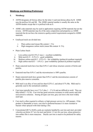
  • 9. 9 / 39 i. P-1 Plain carbon steels, C-Mn-Si, C-Mn, and C-Si steels. ii. P-3 Low alloy steels obtained by additions of up to ¾ % of Mn, Ni, Mo, or Cr, or combinations of these elements. iii. P-4 Low alloy steels with higher additions of Cr or Mo or some Ni, to a max. of 2% Cr., ½ % Mo. iv. P-5 Covers a broad range of alloys varying from 2.25 Cr-1Mo to 9 Cr- 1Mo. 5A Up to 3% Cr, ½ - 1% Mo. 5B 3 – 9 % Cr, 1 % Mo. 5C Strength has been improved by heat treatment (85 ksi or higher). v. P-7 Ferritic stainless steels (seldom used piping material) vi. P-8 Austenitic stainless steels (i.e. 200 and 300 series). vii. P-10H Duplex stainless steels. viii. P-10I,J,K Ferritic stainless steels. ix. P-11 Heat treated low and intermediate alloy steels. x. P-44 Nickel-base alloy (e.g. Hastelloy) xi. P-45 Nickel-base alloy (e.g. solution-annealed Incoloy) Note: Alloys of P-5 and higher groupings require protection from oxidationduring welding, which is often accomplished by purging the inside of the pipe with Ar or N. P-10 materials are commonly used in low-temperature applications. • Clean surfaces are important in TIG welding because the process does not include a flux to float off impurities. • When Al or Ti is welded, the surfaces and filler metal often must be treated chemically to remove oxides. • Section IX does not establish when notch-toughness tests are required. Notch-toughness requirements are established by the construction specifications by specifying impact test requirements. • Sect VIII Div 1 Part UHT requires impact testing for the ferritic materials with properties enhanced by heat treatment. • A material notch-toughness property may be reduced with an increase in heat input. • Two ways to ensure that a selected steel has adequate toughness for the design metal temperature: CharpyV-notchImpact energy,CVN(J) Temp (o C)-50 0 0.2 % C 0.41 % C Upper shelf energy Lower shelf energy Impact Transition Temp Nil Ductility Temp. 0.31 % C 0.11 % C
  • 10. 10 / 39 i. Impact toughness testing of samples at or below design metal temperature (MDMT). ii. Select a material whose impact transition temperature is below the design metal temperature, so that impact testing is not required. Note: 1. Method (ii) is generally preferred as impact testing adds a premium of about 10% to the cost of the plate. • Factors affecting notch toughness: i. Temperature ii. Grain size iii. Deoxidation iv. Carbon content Carbon increases the transition temperature and decreases the fracture energy. Carbon content should be kept low. v. Heat treatment Normalized or quenched and tempered steels have lower transition temperature than as-rolled plates. vi. Heat input Higher transition temperature in the HAZ compared to the base material. Notch toughness may be reduced with increase in heat input. vii. Thickness For a given material the fracture toughness decreases with increasing thickness. Brittle fracture has not occurred in tanks with shell plates less than ½” thick. Any tank that uses ½” thick or less plate for its shell is exempted from brittle fracture concerns. • Factors that increase heat input: i. A higher welding heat input. ii. A higher maximum interpass temperature. iii. A longer PWHT time. iv. A reduction in base metal thickness (i.e. slower heat dissipation). v. A change to uphill progression in vertical welding. vi. A change from stringer bead to weave bead welding. vii. The location in a pipe where the test specimen is removed. The heat input varied in a pipe welded in the 5G and 6G positions; the upper portion of the pipe receives more heat input than that of the lower portion because heat rises. As such, QW-463.1(f), Sect IX mandates that the test specimen of pipe welded in 5G and 6G positions shall be removed only from specified portions of the pipe.. • For non-notch-toughness applications, the Code requires the UTS and ductility properties of a PQR test coupon to be established. For notch-toughness applications, the notch- toughness properties of a PQR test coupon are to be established, in addition to the non- notch-toughness properties. • Notch-toughness requirements are mandatory for all P-11 quenched and tempered metals.
  • 11. 11 / 39 • Supplemental essential variable becomes an essential variable only if notch toughness testing is required. • As ASME Section I vessels are usually quite warm when pressurized, Sect. I does not require notch toughness, or impact testing, and supplemental essential variables are not used in welding for Sect I construction. • P-Number groupings: i. To reduce the no. of WPS required, P-numbers are assigned to base metals depending on characteristics such as composition, weldability, and mechanical properties. ii. The same P-number groups the various base metals having comparable characteristics. iii. Groups within P numbers are assigned for ferrous metals for the purpose of procedure qualifications where notch toughness requirements are specified. iv. If a P number is not available for the material involved, its ASTM specification number may be used. If an ASTM specification number is not available, the chemical analysis and mechanical properties can be used. v. Group numbers subclassify the base metals within P-numbers for the purpose of procedure qualification where notch-toughness requirements are specified by the construction code. • S-Number groupings: i. The use of S-Number is not mandatory. ii. PQR of a base metal in one P-Number qualifies that procedure for all other base metals in the same S-Number, but not vice versa. iii. Performance qualification with P-Numbers qualifies a welder for the corresponding S-Number, and vice versa. • F-Number groupings: i. To reduce the number of PQR and WPQR. ii. Welding filler metals are categorized based on their usability characteristics, which determine the ability of welders to make satisfactory welds. iii. Welder qualification with a filler metal that is more difficult to use qualifies a welder to use a filler metal that is easier to use. iv. The ASME specification numbers are the same as the AWS specification numbers with the addition of the letter SE. • A-Number groupings: i. Weld metal composition is categorized into different A-Number groupings. ii. A-Number is used for the classification of ferrous weld metal for procedure qualification. iii. A-Number can be an essential variable for the WPS. iv. A-Number is not an essential variable for welder performance qualification. • OFW may be used only if the following conditions are satisfied: i. Small-bore steel piping (i.e. < 2”) ii. Base material is either C or C-Mn steel. iii. Base material thickness < 5 mm. iv. Tensile strength of material < 66 ksi.
  • 12. 12 / 39 • GMAW is commonly used in fabrication shops. GMAW may be used for all-position root- and cover-pass welding, up to a maximum current of about 250 amps. With higher currents, welding is restricted to the downhand position, in which case the wires are often composites. The following are are-welding processes: i. SMAW (slag shielded) ii. GTAW (TIG or PAW) (gas shielded) iii. GMAW (MIG) (gas shielded) – deep penetration iv. FCAW (slag shielded) – deep penetration v. SAW (slag shielded) – deep penetration GMAW (which includes MIG) always use a continuous electrode wire, thus they can produce more kgs of weld metal per hour. Characteristics SMAW GTAW GMAW FCAW SAW Weld quality Good Excellent Excellent Good Excellent Weld disposition rate Fair Poor Good Good Excellent Field work Excellent Poor Fair Excellent Poor Equipment maintenance Low Low Medium Medium Medium Fume emission High Low Medium High Very low Arc visibility and filler- metal placement Good Excellent Satisfactory Satisfactory Poor Variety of metals weldable Excellent Excellent Good Good Fair • The conditions that determine the electrical power specifications for arc welding are the thickness of base metal, procedure position, and the specified electrodes. • Joint Preparation for TIG: i. Butt joint shapes a. Single-V The amount of root opening and the thickness of the root face or land depends upon whether the TIG process is to be manual or automatic, whether the filler metal is to be added during the root pass, and whether a backing strip is to be used. b. Double-V Ø Used when thicker sections require complete joint penetration and a single-V butt joint would require too big an opening at the top of the V. Ø Double-V will use less filler metal and cost less to make thicker sections than a single-V. c. Single-U Ø U-joint is quite expensive to make. Also, it requires more filler metaland more welding labor. Ø Used on materials such as Ti and Al are extremely fluid when molten, and they are difficult to weld without internal backing or a consumable insert in the root gap. Ø Employed when working on thick pipes where it is only feasible to weld from one side, (Although a double-V joint to join the thick material from both sides is preferred.)
  • 13. ii. Bevel angles a. Edge beveling is not usually needed for butt joints 3mm (1/8”) or less in thickness in C.S., low-alloy steels, stainless steels, and Al. b. For high-Ni alloys, beveling is not needed for material 2.4 mm (3/32”) thick or less. c. For thicknesses greater than condition (a) or (b), the joint should be beveled to form a V, U or J groove. d. V-groove joints: i. 60o groove for carbon, low-alloy, and stainless steels. ii. 80o groove for high-nickelalloys. iii. 90o groove for welding Al with a.c. TIG. e. U-groove joints: i. 7 – 9 o sidewall bevel for carbon, low-alloy, and stainless steels. ii. 15o sidewall bevel for high-Ni alloys. iii. 20 – 30o sidewall bevel for welding Al. f. Single-bevel T joints (between dissimilar thicknesses): i. 45o groove for carbon, low-alloy, and stainless steels. ii. 60o groove for welding Al alloys. g. A double-V or double-U joint is preferred for material over 12 mm (1/2 “) thick. The added cost of preparation is justified by the decreased amount of weld metal and lower welding time needed to complete the joint. In addition, less residual stress will be developed than with the single-groove joint designs. Note: Ni-base filler metals require larger groove angle to allow for the manipulation of the sluggish weld pool. • TIG welding process: i. TIG and GTAW are the same processes and the abbreviations are used interchangeably. ii. Scratch starting should not be used. iii. It can weld just about any metal, even cast irons. iv. It requires continuous weld-metal shielding with moderately expensive inert gases. v. Backup inert-gas shielding in the opposite side of the weld is needed in some applications, especially when welding Ti, and often when working on thin sections of easily oxidized metals. vi. TIG and MIG welding are the only methods for joining Ti and Al. vii. TIG is most often chosen for root-pass welding of alloy, or otherwise critical piping that call for a smooth root-pass to reduce stress concentration. viii. TIG is widely used for welding stainless steels, especially for full- penetration welds in thin-gage materials and root passes in thicker materials. ix. TIG welding is generally recommended for root passes in one-sided welding ofduplex stainless steels. x. In TIG welding of fully austenitic stainless steels, it is often advisable to add filler metal even when it does not appear to be needed. The proper addition of filler metal can be used to obtain a convexbead shape, which
  • 14. 14 / 39 has better resistance to hot cracking than does the flat or slightly concave weld shape that often results when no filler metal is added. • Shielding Gas for TIG i. Ar or He is used as shielding gas because of their limited solubility in most metals. Mixtures of Ar and He are used when some balance between the characteristics of individual gases is desired. ii. Ar is the most commonly used TIG shielding gas as it provides a lower arc voltage than He at any given current and arc length. Arc starting in Ar is also easier than in He. iii. When welding in the downhand position, lower flow rates are required from Ar to provide shielding as Ar is a heavy gas. iv. When welding overhead, higher flowrates are required from Ar since Ar will tend to sink as it cools. v. Ar is used for welding lighter sections because it produces less heat and therefore less base metal distortion with less chance of burn through when welding thinner material. vi. Automatic welding setups may include supplemental shielding gas over the weld area, with leading or trailing gas shields that increase the coverage. Purge times must be set to allow the weld metal to cool for a longer period before it is exposed to atmosphere. vii. Shielding and backing gases have an effect on the N content of the weld metal. A loss of N can have a negative impact on corrosion resistance of duplex stainless steels especially in TIG welding. viii. He or Ar-He mixture are used as shielding gases for heavy sections to achieve greater heat input or higher welding speeds. ix. Additions of 5% H2 to Ar gas shielding have been used for austenitic stainless steels to provide higher heat input and a cleaner weld surface. x. Drafts, low gas-flow rates, or excessively high gas-flow rates can cause air to enter the arc, thus enabling N2 pickup in the weld metal. Proper gas-flow rates, typically 0.3 – 0.8 m3 /h, and barriers that prevent moving air from reaching the arc area can be used to prevent N2 pickup. • An essential variable for a weld procedure (PQR) is one which, if changed, would affect the properties of the weldment and thus require requalification of the procedure (i.e. additional testing and issuance of a new PQR to support the changed WPS). • A nonessential variable for a weld procedure (PQR) is one that can be changed without requiring requalification, although it would require a change in the WPS. • An essential variable for welder performance is one that would affect the ability of a welder to deposit sound weld metal. • In general, welders who meet the code requirements for groove welds are also qualified for fillet welds, but not vice versa. • Welders who are eligible to weld pipes shall be eligible to weld plates but not vice versa. • When a welder has not welded with any process for a period of 3 months, all his qualifications shall expire.
  • 15. 15 / 39 • When the welder has not welded with a particular process for a period of 3 months or more, his qualifications for that process shall expire; except when the welder is welding with another process in which case, the period may be extended to 6 months. • In B31.1, all welds (including tack welds) in boiler external piping require preheat. • In B31.1, the thickness for consideration of preheat is the greater of the nominal thicknesses at the weld for the parts to be joined. • ASME Sect I does not normally mandate preheat. • Per PW-39 Sect I, all welded pressure parts of power boilers shall be given a PWHT unless otherwise specifically exempted. • Materials for which PWHT is neither required nor prohibited: i. P-8 (austenitic stainless steels) ii. P-45 (nickel and nickel-based alloys) • For P-10 Gp 1 material (ferritic stainless steels), PWHT is always required. • Difference between ASME Sect I and B31.1 with regards to PWHT: Sect I requires the PWHT of a small pipe connection to another pipe or header, while B31.1 often does not. • Items to be recorded in the WPS: i. Base Metals a. The P-No. must be indicated. If a P number is not available for the material involved, its ASTM specification number may be used. If an ASTM specification number is not available, the chemical analysis and mechanical properties can be used b. The thickness range must be shown, and if it is of pipe, the pipe diameter range must be shown. This is because base metal thickness influences cooling rate and, therefore, metallurgical and mechanical properties. Also, the composition of a metal may also change with thickness. c. Very thick sections provide a 3-direction heat dissipation while thinner sections only provide a 2-directional heat dissipation. The thinner sections, with the slower heat dissipation with the resultant longer time at the higher temperature, may be more prone to deterioration of the notch-toughness properties than are the thicker sections. d. The maximum heat input must be limited on certain types of materials, such as heat-treated materials that have been quenched, tempered, age hardened, as well as other heat-treated or cold-worked materials. High heat input processes are unsuitable for these applications. e. Qualification in pipe also qualifies for plate welding and vice versa. f. ASME code permits the qualification on one thickness of test specimen to cover a range of base metal thicknesses. ii. Filler Metals
  • 16. 16 / 39 a. The ASME SFA specification number of the filler metal shall be specified. b. The AWS classification number of the filler metal shall be specified.. c. The filler metal must be produced to an ASME SFA specification, and within that specification it must be produced to an AWS classification. d. The addition or deletion of a consumable insert is an essential variable. e. The size of the filler metal (i.e. diameter) used. f. Deposited weld metal thickness range for groove or fillet welds. g. For submerged arc welding (SMAW), the electrode flux class and the flux trade name must be shown. h. For gas tungsten arc welding (TIG), the consumable insert analysis should be shown. iii. Positions a. The welding position of the groove or fillet weld must be described. b. For vertical welding, it should be mentioned whether progression is uphill or downhill. c. When notch toughness tests are required, a change from any position to the vertical uphill progression requires requalification of the WPS. d. Welding a notch-toughness PQR test coupon in any of the vertical positions, with an uphill progression, will qualify the WPS for all positions. e. Unless specifically required otherwise by the welding variable (QW-250), a qualification in any position qualifies the procedure for all positions. iv. Preheat a. Whether or not preheat is required is determined by the carbon equivalent (C.E) number. b. The min. temp. shall be given as well as the max. interpass temperature. The max. interpass temperature shall be controlled to assure it does not exceed the interpass temperature of the PQR by more than 100 o F. c. The interpass temperature must be controlled as the notch toughness properties could deteriorate with ever increasing interpass temperatures. d. Preheat maintenance temp should be given. e. For medium-carbon steels (0.25 – 0.6%) the preheat temperature ranges from 120 – 205 o C. f. For high-carbon steels (0.6 – 1.0%) the temperature ranges from 205 – 260o C, interpass temperature ranges from 205 – 290o C. g. ASME Sect IX permits an increase or decrease of up to 100o F (56o C) before requalification is required. v. PWHT a. The use of PWHT, as well as changes in the heat treatment temperature or time at temperature, will require requalification of PQR. b. If required, the temperature range and the time at temperature shall be indicated. c. For medium-carbon steels (0.25 – 0.6%) the temperature ranges from 595 – 620 o C. d. For high-carbon steels (0.6 – 1.0%) the temperature ranges from 620 – 650 o C. vi. Shielding Gas
  • 17. 17 / 39 a. The use and the composition of a shielding gas are essential variables for arc welding. b. It protects the molten metal from atmospheric O2 and N2 as the weld pool is being formed. c. It promotes a stable arc and uniform metal transfer. d. It can affect the weld bead shape and penetration pattern. e. It interacts with base metals and with filler material to produce the basic strength, toughness, and corrosion resistance of the weld. f. In GMAW and FCAW, the gas used has an influence on the form of metal transfer (e.g. spray transfer, globular transfer, short circuiting transfer) during welding. g. In GTAW, typical flow rates for Ar are 7 L/min and 14 L/min for He. vii. Electrical characteristics a. Three choices: DCEN, DCEP, a.c. b. DCEP produces shallowpenetration, wide bead. c. DCEN produces deep penetration, narrowbead. d. Alternating current (a.c.) produces medium penetration and bead width. e. Variations in the type of welding current or in polarity normally require requalification. f. A small change in welding current or voltage does not typically require requalification. h. Many codes limit changes to ±10% from the mean value, withoug necessitating requalification. viii. Technique a. The WPS shall require requalification if the PQR was welded with stringer beads, and the WPS will be applied using weave beads. b. Changing the direction of welding (i.e from downhill to uphill) for vertical arc welding procedures require requalification of PQR. c. Changes in mean travel speed of more than 10% require requalification of PQR. • Shielding/Backing Gases a. Components of a shielding gas blend: Argon: Ø With low ionization potential, Ar promotes easy arc starting and stable arc operation. Ø Its low thermal conductivity promotes the development of axial ‘spray’ transfer in certain forms of GMAW. Helium: Ø With high ionization potential and thermal conductivity, He transfer more heat to the base material, thus enhancing the penetration characteristics of the arc. Ø It allows higher weld travel speeds to be obtained.
  • 18. 18 / 39 Ø Because of its higher cost, He is frequently combined with Ar or Ar mixtures to enhance the overall performance of the blend while minimizing its cost. Oxygen: Ø Small amounts of O2 are added to some inert mixtures to improve the stability of the welding arc developed as well as to increase the fluidity of the weld puddle. Ø In the spray transfer mode of GMAW, small additions of O2 enhance the range Carbon Dioxide: Ø It is commonly used alone in certain types of GMAW. Ø It is added to Ar blends to improve arc stability, enhance penetration, and improve weld puddle flow characteristics. Ø The higher thermal conductivity of CO2- transfers more heat to the base material than does Ar alone. Hydrogen: Ø It is added to inert gases to increase the heat input to the base material or for operations involving cutting and gouging. Ø Because some materials are especially sensitive to hydrogen-related contaminations, its use is generally limited to plasma arc cutting and gouging, and the joining of stainless steels. Nitrogen: Ø It is not used as a primary shielding gas as it will react with some metals (e.g. steel, Ti, Al, Mn) at arc welding temperatures. b. Ar and He have no direct effect on the weld metal as they are nonreactive. c. CO2 and O2 will react with elements (e.g. Mn and Si) in the filler metal or base metal and will form a slag on the surface of the weld deposit. The loss of Mn and Si elements from steel can affect the quality of weldment produced. d. Generally, both weld strengthand toughness decline as the oxidizing nature of the shielding gas increases. e. Additions of O2 or CO2 enhance the stability of the arc and affect the type of metal transfer obtained. Metal droplet size is decreased, and the number of droplets transferred per unit time increases as the level of O2 in the shielding gas increases. f. O2 reduces the molten weld bead surface tension, promoting better bead wetting and higher welding travel speeds. g. Pure Ar produces a sluggish weld puddle and a high, crowned head. The additions of small amount of O2 lowers the surface tension and promotes fluidity and better wetting of the base material.
  • 19. 19 / 39 h. When welding in horizontal / flat positions, gases heavier than air require lower flow rates in use than do the lighter gases to ensure adequate protection of the weld puddle. When welding in overhead position, Ar requires higher flow rates in use than do He. • Arc welding of carbon steels (up to 2% C, 1.65% Mn, 0.65%Si, 0.6% Cu): i. Weldability Ø < 0.15% C: The steels are nonhardening and weldability is excellent. Ø 0.15 – 0.3% C: As hardening is a possibility, preheating may be required at higher Mn levels, in thicker sections, or at high levels of joint restraint. Ø 0.3 – 0.6% C The higher carbon content, along with Mn, makes these steels more hardenable. Preheating and postheating treatments are necessary. Low- hydrogen consumables and procedures should be used to reduce the likelihood of hydrogen-induced cracking. Ø 0.6 – 2% C Likelihood of formation of hard, brittle martensite upon weld cooling. Low-hydrogen consumables and procedures, preheating, interpass control, and stress relieving are essential to prevent cracking. Austenitic stainless steel electrodes are sometimes used to weld high-carbon steels to reduce the risk of hydrogen-induced cracking but may not match the strength of the high-carbon steel base metal. ii. Welding Processes a. SMAW A flux-using process A lower-heat-input process and cooling rates can be high. The weld metal can pick up O2 from decomposition of metal oxides contained within the flux. Arc voltage varies from 15 – 35V, amperage varies from 25 – 500 A. The electrode manufacturer should recommend an optimum range for each size and type of electrode. b. GTAW, TIG, PAW They are nonflux process – less tolerant of rust and scale on base metal. They produce the lowest gaseous impurity level in weld metal. The arc in these processes are short and stable, and the shielding gases are inert and make no contribution to gaseous impurities in weld metal. c. SAW A flux-using process that is most commonly used to join plain carbon steels. The weld metal can pick up O2 from decomposition of metal oxides contained within the flux. It is a high dilution process (i.e. a large amount of base metal will be incorporated into the weld). Some submerged arc welds are more prone to N2 pickup when a.c. power is used.
  • 20. 20 / 39 A high current process capable of high heat input, high penetration, high rate of travel, and high deposition rates. Because of the high heat input, SAW is most commonly used to join steels more than 6.4 mm thick. d. GMAW It is a nonflux process – less tolerant to rust and scale on base metals. The weld deposits are higher in both O2 and N2 as compared with GTAW/TIG/PAW. A longer, less stable arc allows a greater chance of gaseous impurities pickup. The use of ArO2, Ar-CO2, or CO2 shielding gases also raises the O2 level of the weld metal. The pulsed arc and short circuiting modes of GMAW are better suited to welding a vertical fillet than are the globular and spray modes. e. FCAW A flux-using process. The weld metal can pick up O2 from decomposition of metal oxides contained within the flux. iii. Welding Consummables a. SMAW AWS A5.1 E60XX electrodes: Suitable for welding carbon steels containing up to about 0.3%C. It should not be used to weld hardenable steels. b. GMAW AWS A5.18 for carbon steel filler metals. AWS A5.28 for low-alloy steel electrodes used to weld medium- and high- carbon steels.. c. TIG, PAW ….. d. SAW ….. e. FCAW ……. iv. Preheat ……………. v. PWHT Postweld heat treating of carbon steels is normally performed in the 600 – 650 o C range.
  • 21. 21 / 39 • Welding of low-alloy steels (0.1 – 0.3% C, up to 10% total alloy) for Pressure Vessels and Piping i. Shielding Gases: The type of shielding gases has a significant effect on the mechanical properties of welds in low-alloy steels. a. TIG Ø 100% welding grade (99.995%) Ar. Ø Ar is commonly used when gas backing is specified. Ø N can also be used as a backing gas for many applications. b. GMAW, FCAW Ø The selection of shielding gases often depends on filler metal characteristics. Information should be obtained from filler metal manufacturer. Ø Ar-O2 and Ar-CO2 mixtures are commonly used. Ø Either Ar-He-CO2 mixtures or 100% CO2 are used for low-heat-input welding that utilizes small-diameter electrodes and a short-circuiting mode of metal transfer. Ø Depending on the original carbon content of the electrode, a CO2 shielding atmosphere can result in either an increase or decrease in the carbon content of undiluted weld metal; if the carbon content of the electrode is < 0.05%, then the weld metal tends to pick up carbon from the CO2 shielding gas. If the carbon content of the electrode is > 0.1%, then the weld metal tends to lose carbon. ii. Filler metals Ø The use of low-hydrogen consumables is essential. (i.e. E7015, E7016, E7018, E7018M, E7028, E7048.) Ø In general, the content of critical elements in the weld metal must either match or exceed that of the base metal. Ø SMAW: ANSI/AWS spec A5.5 Ø GMAW: ANSI/AWS specs A5.28 and A5.9 (ER502 and ER505 filler metals for the welding of 5Cr-0.5Mo and 9Cr-1Mo base metals, respectively.). Ø SAW: ANSI/AWS spec A5.23. Desirable to consult manufacturers of electrodes and fluxes for recommendations on electrode/flux combinations. To avoid hydrogen-induced cracking, care should be taken to maintain the flux and electrode in a dry condition. Ø FCAW:
  • 22. 22 / 39 ANSI/AWS spec A5.29. ANSI/AWS A5.22 classifies E502T-X and E505T-X flux-cored electrodes for welding 5Cr-0.5Mo, 7Cr-0.5Mo, and 9Cr-1Mo base metals. iii. Heat Input Control of heat input is essential when notch toughness requirements are important. iv. Preheating The appropriate sections of the Code should be consulted for preheat recommendations. The need for preheating increases with increasing carbon and alloy content and with increasing steel thickness. v. PWHT PWHT is often essential for welds in low-alloy steels used for pressure vessels and piping. The applicable sections of the ASME Code should be consulted for specific detailed PWHT requirements. • Temper embrittlement is possible during the tempering of alloy and low-alloy steels. This embrittlement occurs when quenched-and-tempered steels are heated in, or slow cooled through the 340 – 565 o C temperature range. Embrittlement occurs when the embrittling elements, antimony, tin, and phosphorus, concentrate at the austenite grain boundaries and create intergranular segregation that leads to intergranular fracture. Mo has been shown to be beneficial in preventing temper embrittlement. • Welding of cast-iron (primarily for repair of cracks in castings) i. For oxyacetylene welding, a preheat of 650 - 700o C will be required. The leftward technique and cast iron filler rod and flux should be used. ii. For SMAW, only complicated castings should require preheating. iii. If castings are arc welded without preheat, skip welding and peening should be employed to reduce the contraction stresses. iv. There are 4 main types of electrode for SMAW: a. (55% Ni 45% Fe) core wire electrode b. Electrodes with a core wire of Monel metal. c. Electrodes with a core wire of low-C mild steel. This type is sometimes used for the welding of thick section repairs and will require full preheating if machining is required. d. Electrodes with bronze core wire. They can be used for the repair of thin section castings and malleable iron. Preheating is not required. v. To prevent spreading of a crack during welding, small holes are drilled at each end of the crack. vi. For full-thickness welds a buttering layer can be deposited on each face, using Ni-alloyelectrodes. The bulk of the weld can be completed by using less expensive low-C steel electrodes which, because of the buttering layer, will no longer be affected by the C in the casting.
  • 23. 23 / 39 • Types of stainless steels i. Austenitic: 18 – 20 % Cr, > 7% Ni ii. Ferritic: 13 – 20 % Cr, < 0.1% C, with no Ni iii. Martensitic: 12 - % Cr, 0.2 % < C < 0.4 %, up to 2% Ni iv. Super austenitic stainless steel: 20% Cr, 29 – 30% Ni v. Duplex stainless steel: 22% Cr, 5% Ni, 3% Mo, 0.15%N The most common is probably type 2205. It is used in pressure vessels, piping, valves, fittings, and pumps for offshore oil collection. vi. Super-duplex stainless steel: 25% Cr, 7% Ni, 4% Mo, 0.25%N Alloy 255 is the most common. • Stainless steels properties: i. Ferrite phase provide mechanical strength and stress corrosion resistance. ii. Austenite phase provides ductility even at low temperatures. iii. Used for corrosion resistance when oxidizing conditions exist. iv. All ferritic, austenitic, and martensitic stainless steels are susceptible to pitting from exposure to high chloride concentrations. However, austenitic stainless steels with a high Mo content (1 – 5%) have improved resistance to pitting. v. Mo is added to Type 316 to improve the corrosion resistance in reducing conditions. vi. Although austenitic stainless steels have excellent corrosion characteristics at temperatures up to 343o C, they experience with stress-corrosion cracking at high temperatures with high-pH (8 or more) fluids. vii. Austenitic stainless steel, unlike plain carbon steel, does not become brittle at low temperatures. viii. Thermal conductivity of stainless steel is significantly lower than that of carbon steel ix. Austenitic stainless steels are non-magnetic in the annealed conditionwhereas ferritic stainless steels are magnetic. x. Because of 475o C embrittlement and sigma-phase embrittlement, long-term service temperatures for most ferrite stainless steels are usually limited to 250o C. xi. Alloys with greater than 25% Cr are susceptible to embrittlement due to sigma phase formation at temperatures above 500o C xii. Super austenitic stainless steels have good resistance to acids and acid chlorides. xiii. Duplex stainless steels have a better corrosion resistance than the austenitic stainless steels and are less susceptible to stress corrosion cracking. xiv. The yield strength of duplex stainless steels is on the order of twice that of ordinary austenitic stainless steels. xv. Super-duplex stainless steels are developed for use in aggressive off-shore environments. xvi. Duplex stainless steels should not be used at working temperatures above approximately 300o C. Sigma phase embrittlement can occur above 475o C. xvii. As austenitic stainless steels are particularly susceptible to stress corrosion cracking, ASME Section I generally limits the use of these steels to so-called steam-touched service and prohibits their use for water-wetted service, where chlorides or sulfides might be present. An exception is made for surfaces that are water-wetted only during start-up of the boiler, since this is considered short enough time that the risk of corrosion is quite limited. • Stainless steels welding:
  • 24. 24 / 39 i. Fully austenitic weld deposits are occasionally susceptible to hot-short cracking. The presence of a small fraction of delta ferrite phase in an austenitic weld deposit helps to prevent of both centerline cracking and fissuring. ii. A deposit that is primarily austenitic will not cold crack. iii. Excessive delta ferrite can have adverse effects on weld metal properties. The greater the amount of delta ferrite, the lower the weld metal ductility and toughness. Delta ferrite is also preferentially attacked in a few corrosive environments (e.g urea). iv. As the presence of ferrite usually inhibits the tendency to hot-short crack, many austenitic stainless steel electrodes are designed to deposit a weld metal containing sufficient ferrite to reduce the susceptibility to hot cracking. Thus, the weld metal for many of the standard austenitic grades may contain ferrite, although the same grade base metal does not contain any. v. PWHT may decrease or even eliminate the ferrite in a weld deposit. vi. The welding filler metal must at least match (and sometimes overmatch) the contents of the base metal in terms of specific alloying elements, such as Cr, Ni, and Mo. vii. The ferrite content recommended in weld filler metal is usually between 3 – 20%. A minimum of 3% ferrite is desirable to avoid microfissuring in welds. Up to 20% ferrite is permitted when needed to offset dilution losses. viii. A FN around 4 or 5, minimum, typically suffices to prevent hot cracking. ix. Careless welder can change the FN of a filler metal by permitting N2 from the air to enter the welding arc. This is because practices such as long arc length in SMAW or FCAW can produce enough N2 pickup to reduce the ferrite of an otherwise satisfactory weld deposit to an unacceptably low level, which makes hot cracking possible. x. Schaeffler diagram has been extensively used for estimating the ferrite content of stainless steel weld metals. It is reasonably accurate for conventional ‘300-series’ stainless steel weld deposits from covered electrodes, but it is of limited use when less-conventional compositions are used and when a high level of N is present. It offers prediction of Creq from 0 to 40 and Nieq from 0 to 32.
  • 25. 25 / 39 Problems with Schaeffler diagram: Schaeffler diagram does not consider the effect of nitrogen in promoting austenite at the expense of ferrite, and it is incorrect in its treatment of Mn. Mn does not promote the high-temperature formation of austenite at the expense of ferrite, as predicted by the diagram, although Mn does stabilize austenite in its low- temperature transformation to martensite. xi. WRC-1992 is more accurate than Schaeffler diagram in predicting the ferrite content for many weld metal but does not include Mn. It offers prediction of Creq from 17 to 31 and Nieq from 9 to 18. It is useful in predicting the FN for dissimilar metal joints. xii. If the weld metal solidifies as ferrite first, with austenite appearing only in the later stages of solidification, if at all, then the weld metal will be crack resistant. However, if the weld metal solidifies as austenite first, with ferrite only appearing in the later stages of solidification, if at all, then the weld metal is at risk for cracking. In WRC-1992 diagram, the dividing line between compositions that solidify as austenite first and compositions that solidify as ferrite first is approximated by the dashed line between the areas labeled ‘AF’ and ‘FA’. (Note: ‘AF’ – primary austenite solidification ‘FA’ – primary ferrite solidification) xiii. Weld puddle shape has a strong influence on hot-cracking tendencies. Narrow, deep puddles crack more readily than wide, shallow puddles. It is desirable to adjust welding conditions to obtain a weld pool that is elliptical in surface shape and to avoid tear-drop-shaped weld pools, the sharp tail of which tends to promote hot cracking. Low current and slow travel speed favor an elliptical pool shape. xiv. When non-low-carbon grades are welded and sensitization that is due to chromium carbide precipitation cannot be tolerated, then annealing at 1050 – 1150 o C, followed by a water quench, can be used to dissolve all carbides and sigma-phase.
  • 26. 26 / 39 This annealing heat treatment also causes much of the ferrite that is present to transform to austenite. • Duplex stainless steels welding: i. Only plasma cutting is allowed, oxyfuel cutting is prohibited. ii. TIG welding is generally recommended for root passes in one-sided welding. iii. An excessively high ferrite content will cause sigma phase embrittlement, whereas a lack of ferrite will cause a loss of resistance to stress corrosion cracking. The weld metal ferrite content should be in the range of FN 30 – 100 (approx. 22 – 70 %) iv. A restriction to a maximum of 85 FN (approx. 60%) may be required at locations exposed to a corrosive environment or where diffusible hydrogen and strain may otherwise initiate hydrogen cracking. v. Chromium nitride formation affects corrosion resistance and is mainly seenin high ferrite content regions. Base metals with a high N content are less sensitive to nitride precipitation in the HAZ since N is a austenite former and suppresses nitride formation. Nitride precipitation normally does not occur provided that the filler metal is overalloyed with Ni and the recommended heat input limits are observed. vi. Overly high cooling rates result in overly high ferrite content and low toughness and reduced corrosion resistance (due to nitride precipitation). Overly low cooling rates can result in the formation of embrittlement phases during cooling and a deterioration in corrosion resistance. vii. Heat input and interpass temperature: a. Duplex stainless steel: 0.5 – 2.5 kJ/mm, Ti,max = 200 o C b. Super-duplex stainless steel: 0.2 – 1.5 kJ/mm, Ti,max = 150 o C Note: 1. Super-duplex steels are particularly sensitive to high heat input and interpass temperature. 2. Heat input should not exceed 1 kJ/mm when welding thin plates. 3. The limitation on heat input serves to promote austenite formation in the HAZ, as well as in the weld metal. viii. The upper heat input and interpass temperature limits are set to prevent sigma- phase formation and the lower limits to avoid chromium nitride precipitationwhich deteriorates the corrosion resistance. (NB: Too rapid cooling rate will trap N2 in ferrite, and results in chromium nitride precipitation.) ix. Duplex filler metals are overalloyed in Ni. Overalloying with Ni ensures the formation of a sufficient amount of austenite in weld metal during cooling. Typical composition of a duplex consumable is 22% Cr, 9% Ni, 3% Mo, 0.17% N. x. Shielding and backing gases have an effect on the N content of the weld metal. A loss of N can have a negative impact on corrosion resistance especially in TIG welding. xi. An adequate root gas shielding is essential when welding duplex steels. Suitable backing gases are high purity Ar, mixtures of Ar+N2 or pure N2. Shielding and backing gases with N2 additions can be used in critical applications to improve corrosion resistance. xii. With the TIG process, especially for the root pass, it is important to design the welding procedure to limit dilution of the weld metal (Ni content) by the base metal. This is achieved by using a wider than normal root opening and more filler metal in the root than one would use for an austenitic stainless steel joint. xiii. The 2209 filler metal composition is a match for type 2205 base metal. The 2553 filler metal composition is a match for alloy 255 base metal.
  • 27. 27 / 39 xiv. The PWHT of duplex stainless steels needs to be done at temperatures above 1040 o C or not at all because sigma-phase and other intermetallic compounds can form in the temperature range from 500 to 1000 o C. Also, temper embrittlement can occur at temperatures as low as 250 o C to as high as 550 o C, depending on composition and time at temperature. xv. Welding voltage is determined by the arc length that the welder holds. A short arc length is desired because a long arc length permits more air to enter the arc and weld metal. N2 from the air can be picked up by the weld metal and become an alloying element, and leading to undesirable primary austenite solidification instead of primary ferrite solidification. (NB: Hot crack is caused by primary austenite solidification.) xvi. Unlike welding of low-alloy steels, preheat and interpass temperature control are not practiced with duplex stainless steel weldments for the purpose of hydrogen cracking protection, but for HAZ microstructure control. xvii. A min preheat of 100 o C and a max interpass temperature of 200 o C can be recommended for most duplex stainless steel weldments. • Nickel alloys: a. Addition of Cu to Ni improves resistance to acids under reducing conditions. b. Monel (70 % Ni – 30 % Cu) pits in stagnant seawater and behaves best in flowing, aerated seawater, which ensures uniform O2 supply. c. Inconel 600 (i.e. alloying Ni with Cr) imparts resistance to oxidizing acids (e.g. HNO3) and to oxidation at high temperatures. d. Hastelloy B(alloying 65% Ni with Mo) improves resistance to non-oxidizing acids very substantially. These alloys are resistant to HCL of all concentrations and temperatures up to the boiling point. They are resistant to phosphoric and various organics acids. These alloys are not resistant to oxidizing conditions or to oxidizing metal chlorides. e. Hastelloy C (alloying 55% Ni with both Mo and Cr) is resistant to both oxidizing and reducing conditions because of high Mo and Cr content. These alloys are successfully used in the as-welded conditions with little carbide precipitation along grain boundaries in the HAZ. f. Hastelloy D(alloying Niwith Si) is resistant to H2SO4, H2SO3, H3PO4, and organic acids under a wide variety of temperatures and concentrations. g. Hastelloy F (alloying Ni with Mo, Cr, Fe and about 3 % Nb) is resistant under both oxidizing and reducing conditions. h. Hastelloy Gis resistant under oxidizing and reducing conditions. These alloys have excellent corrosion resistance to hot H2S04 and hot phosphoric acid. i. Hastelloy X is a heat resistant superalloy. The strength and oxidation resistance remain in temperatures up to 1150o C. j. Alloy 31 k. Alloy C-276 l. Alloy B-2 m. Alloy B-4 n. Alloy B-10 o. Alloy 33 p. Alloy 59 q. Incoloy 800/800H Ni = 32% r. Incoloy 825 Ni = 40% s. Inconel 600/625 Ni = 65%
  • 28. 28 / 39 Note: Ni-base alloys are susceptible to embrittlement by Pb, S, P, and some low- melting metals that may be present in lubricants, paints, marking crayons, shop dirt or processing chemicals. • Concentrated, hot, caustic solutions or fluids with high chloride content (i.e. reducing condition) require nickel-base alloys. • High nickel alloys are used for corrosion resistance when reducing conditions (e.g. dil. H2SO4 acid and solutions containing chlorides) exist. • Nickel alloys welding: i. Nickel-alloys are susceptible to embrittlement (or hot shortness of welds) by Pb, S, P, and other low-melting-point elements. ii. Joint design: a. Bevelling is usually not required for metal that is 2.4 mm or less in thickness. b. Metals thicker than 2.4 mm should be beveled to form a V-, U-, or J-shaped groove and should be welded using either a backing material or a gas, unless welding from both sides. Otherwise, erratic penetrationcan result. c. To attain the best underbead contour on joints that cannot be welded from both sides, GTAW (TIG) process should be used for the root pass. d. For metal that is more than 9.5 mm thick, a double U- or V-shaped groove design is preferred. e. Plasma arc cutting can be used for joint preparation, but all oxidized metal must be removed from the joint area by grinding or chipping for a depth of 0.8 to 1.6 mm. f. Molten Ni alloy weld metal does not flow as easily as steel weld metal. For joints in metal up to 16 mm thick, ample accessibility is provided by V-grove butt joints beveled to a 60o groove angle. For thicker metal, U-groove butt joints are machined to a 15o bevel angle and a 4.8 – 7.9 mm radius. g. Single bevels used to form T joints should be at least 9.5 mm and the bevel angle described in (f) should be used for J- and U-shaped grooves. For full- penetration welds, the bevel and groove angles should be about 30% more than those used for carbon steels. iii. GTAW (TIG) process a. Direct current electrode negative (DCEN) is recommended for both manual and machine welding. b. Either Ar or He, or a mixture of the two, is used as a shielding gas. Additions of O2, CO2, or N2 to Ar gas will usually cause porosity or erosion of the electrode. c. Ar with small quantities of H2 (typically 5%) can be used and may help avoid porosity in pure Ni, as well as aid in reducing oxide formation during welding. d. Mixtures of Ar and He help stabilize the arc while maintaining the benefits of the He shielding gas. iv. SMAW process a. DCEP should be used. DCEN will cause weld spatter. b. As molten Ni-alloy weld metal is not as free flowing as iron base alloys, a slight weave is required. The weave should be no wider than approximately 3
  • 29. 29 / 39 times the electrode diameter. A slight weave can help prevent possible centerline solidification cracking problems. c. Weld spatter indicates that the arc is too long, that excessive amperage is being used, or that the current is straight polarity (DCEN). d. Electrodes: Ø ENiCrMo-3 electrodes typically are used to join a wide range of pitting and crevice corrosion-resistant alloys. This type of electrode is widely used because its high Ni content allows good dissimilar weldability, whereas the high Mo content matches or exceeds the pitting resistance of the base alloys being welded. (Note: Because of the strength of the ENiCrMo-3 electrode, welding to many HSLA grade steels can be performed without sacrificing strength.) v. SAW process a. DCEN or DCEP may be used. DCEP is preferred for butt welding because it produces a flatter bead with deeper penetration at a rather low arc voltage (30 – 33 V). b. DCEN results in a slightly higher rate (typically 30% higher) of deposition at increased voltage (over 35V) and requires oscillation. However, the flux covering must be appreciably deeper. Consequently, flux consumption and the risk of slap entrapment increase. c. Joint design: Ø Single V-groove is used for thickness up to 13 mm. Ø Single U-groove and double U-grooves are used for metal that is 19 mm or-+ more thick. Double U-groove is usually preferred because it results in a lower level of residual stress and can be completed in less time, with less filler metal. d. Electrodes: Ø Wire that ranges from 1.14 to 2.36 mm in diameter can be used for all Ni alloys. The 1.6 mm diameter wire is generally preferred. A mall- diameter wires are used to weld metal that is up to 13 mm thick, and 2.4 mm diameter wires are used for heavier sections. • For nickel alloys, weld preparations should have a greater included angle than those used for carbon steel, to minimize the risk of lack of fusion defects due to the low fluidity of the weld metal. • The Hastelloy alloys, and P-44 in particular, must be welded with small stringer beads at a low interpass temperature. This is necessary to preserve the corrosion resistance of the materials and to prevent cracking. • When solution-annealed Incoloy, P-45, is to be joined for high-temperature service, the following precautions must be observed: i. The weld metal selected should match the creep strength of the base material(by choosing ENiCrFe-2. coated electrodes). ii. All weld slag must be removed, because traces of it have been shown to promote corrosion at high temperatures, particularly in a reducing or sulfurous environment. Sand- and grit-blasting is most often specified. • Titanium, when heated over 1000F (538 o C), becomes embrittled if exposed to O2, N2, H2 and other gases. It is important that the weld metal and heated zones be well shielded with inert gas and that all materials be meticulously clean.
  • 30. 30 / 39 • Indices that measure pitting and crevice corrosion resistance: i. Critical pitting temperature (CPT). The temperature above which triggers the onset of pitting corrosion ii. Critical crevice temperature (CCT). The temperature above which triggers the onset of crevice corrosion. Note that the crevice gap (usually 0.2 – 0.5 µm) also has a major influence on the development of a critical crevice. CPT is on the order of 30 o C for duplex stainless steels, and 35 o C or higher for super-duplex. iii. Pitting resistance equivalent number (PREN). PREN = %Cr + 3.3 x %Mo + 16 x %N The higher the PREN, the better the resistance to pitting corrosion. However, alloys having similar values may differ considerably in actual service. Alloys with values greater than 38 offer more corrosion resistance than the austenitic stainless steels. A minimum PRE value of 40 is often used as a definition of a super-duplex stainless steel and weld metal. • Sodium-cellulose based-flux coatings make electrodes that work in all positions. • Electrode flux coatings with a lot of iron powder in them (i.e. Exxx4 and Exxx7) can be used with a.c, DCEP, or DCEN welding current. AWS A5.4 electrodes, and non-ferrous electrodes, for making fill passes over one or more TIG stringer passes. AWS A5.4 electrode has difficulty of making a satisfactory root pass. AWS Classification Description A5.1 C.S. electrodes for SMAW A5.2 Carbon & low-alloy steel rods for Oxyfuel Gas Welding A5.4 Covered corrosion-resisting Cr and Cr-Ni steelwelding A5.5 Low alloy steel covered arc welding electrodes A5.9 Corrosion resisting Cr and Cr-Ni steel bare and composite metal cored and stranded welding electrodes and rods A5.11 Ni and Ni alloy welding electrodes for SMAW A5.12 Tungsten arc welding electrodes A5.13 Solid surfacing welding rods and electrodes A5.14 Ni and Ni alloy bare welding electrodes and rods A5.15 Welding electrodes and rods for cast iron A5.16 Ti and Ti alloy welding electrodes and rods A5.17 Carbon steel electrodes and fluxes for SAW. A5.18 C.S. filler metals for gas shielded arc welding A5.20 C.S. electrodes for FCAW A5.21 Composite surfacing welding rods and electrodes A5.22 Flux cored corrosion-resisting Cr and Cr-Ni steel electrodes A5.23 Low alloy steel electrodes and fluxes for SAW A5.28 Low alloy steel filler metals for gas shielded arc welding A5.29 Low alloy steel electrodes for FCAW • All high-strength steel electrodes (i.e. 5-digit electrodes) in use are AWS Exxxx5, Exxxx6, or Exxxx8 grades because low-hydrogen electrodes are important for welding high-strength steels to prevent hydrogen embrittlement.
  • 31. 31 / 39 • Organic cellulose flux coating would produce hydrogen embrittlement in high-strength welds because all organic materials burn to produce H20, and H2O contains hydrogen. • Low-hydrogen electrodes are good for low-temperature service or for preventing underbead cracking in some materials. • Titania-coated electrodes (e.g. E6012 and E6013) are recommended for fillet welding. Recommended current-type for electrodes of various coatings Last -2 Digit Type of Coating Welding Current 10 High cellulose sodium DC+ 11 High cellulose potassium AC, DC+, or DC- 12 High titania sodkum AC or DC- 13 High titania potassium AC or DC+ 14 Iron power titania AC or DC- or DC+ 15 Low hydrogen sodium DC+ 16 Low hydrogen potassium AC or DC+ 27 Iron powder iron oxide AC or DC+ or DC- 18 Iron powder low hydrogen AC or DC+ 20 High iron oxide AC or DC+ or DC- 22 High iron oxide AC or DC- 24 Iron powder titania AC or DC- or DC+ 28 Low hydrogen potassium iron powder AC or DC+ • A d.c. machine produces a smoother arc. D.c. rated electrodes will only run on a a.c. welding machine. Electrodes which are rated for a.c. welding are more forgiving and can also be used with a d.c. machine. • Electrodes with a high percentage of Ni are commonly used to repair cast irons. Ni is very ductile, making it a good choice to weld on brittle cast iron. • Electrodes that produce welds that do not harden in air on cooling are: i. Stainless steel (E309). ii. Inconeltype (ENiCrFe) iii. Low-carbon (E8018-B2L) • Choosing the right electrode size: i. Large electrodes weld at high currents for high deposit rate. ii. To keep down cost, the largest electrode practical to be consistent with good weld quality is generally chosen. An important exception is in low-temperature applications, such as on P-9 or P-10 materials, because small stringer beads are required in order to meet the specified impact values. iii. Electrode size may be limited on sheet metal and root passes, where burnthrough can occur. iv. As a general rule, 3/16” (4.8 mm) is the maximum electrode size practical for vertical and overhead welding, while 5/32” (4 mm) is the maximum size practical for low hydrogen. • Titanium-stabilized Type 321 stainless steel shall be welded with columbium-stabilized filler metal, Type 347, because Ti cannot be transferred through the welding arc. • Welding dissimilar metals:
  • 32. 32 / 39 i. The filler metal must be compatible with both metals being joined. ii. The filler metal must be able to accept dilution (alloying) by the base metals without producing a crack sensitive microstructure. iii. A successful weld between dissimilar metals is one that is as strong as the weaker of the two metals being joined. iv. Significant difference between the melting temperatures of the two base metals or between those of the weld metal and a base metal can result in rupture of the metal having the lower melting temperature. Solidification and contraction of the metal with the higher melting temperature will induce stresses in the other metal while it is in a weak, partially solidified condition. This problem may be solved by depositing one or more layers of a filler metal of intermediate melting temperature on the face of the base metal with the higher melting temperature. The weld is then made between the buttered face and the other base metal. v. If dilution of austenitic stainless steel filler metal is a problem, it may be controlled by first buttering the joint face of the carbon or low-alloy steel with one or two layers of type 309 or 310 stainless steel filler metal. A low-alloy steel component can be heat-treated after the buttering operation, then joined to the stainless steel part. This avoids a PWHT that might sensitize the austenitic stainless steel to intergranular corrosion. vi. Preheating the base metal of higher thermal conductivity reduces the cooling rate of the weld metal and the HAZ. The net effect of preheating is to reduce the heat needed to melt that base metal. Dilution is more uniform with balanced heating. vii. Ideally, the thermal expansion coefficient of the weld metal should be intermediate between those of the base metals, especially if the difference between those of the two base metals is large. Buttering may also be used to provide a transition between materials with substantially different coefficients of thermal expansion but which must endure cycling temperatures in service. viii. Welding between austenitic stainless steel and carbon or low-alloy steels: a. Austenitic stainless steel (E/ER309/309L/309Cb/347).filler metals for service applications below 425 o C (800 o F). b. High-nickel (ENiCrFe-3, ERNiCrFe-5, or ERNiCr-3) filler metals are used for higher temperatures (> 425 o C) or when high-temperature cyclic service is a concern.. Note: 1. The coefficients of thermal expansion of high-nickel alloys approximate those of ferritic steels, and during cyclic-temperature service, the major differential expansionstresses are located primarily at the tough stainless steel/weld metal interface. 2. Another advantage of nickel-base weld metal markedly reduces carbon migration from the ferritic steels to the weld metal. Extensive carbon migration into stainless steel weld metal weakens the HAZ of the carbon or low-alloy steel. ix. Welding between different grades of low-alloy steels, or between carbon and low-alloy steels: Because of the similarities of these materials, the choice of filler metal is not critical; some fabricators match the properties of the lower alloy, and others those of the higher.
  • 33. 33 / 39 x. For part (iii), the preheating and PWHT requirements of the higher alloy should be followed. • Reasons for preheat: i. Lowers the cooling rate in the base metal and weld metal, producing a more ductile microstructure with greater resistance to cracking. ii. The slower cooling rate provides an opportunity for any hydrogen that may be present to diffuse out harmlessly without causing any cracking. iii. It reduces the shrinkage stresses in the weld and adjacent base metal. iv. It raises some steels above the temperature at which brittle fracture would occur in fabrication. • Factors that determine whether or not preheat is required: i. Code requirement. ii. Section thickness. iii. Base metal chemistry. iv. Joint restraint. v. Ambient temperature. vi. Filler metal hydrogen content. vii. Previous cracking problems. • Preheat requirements: i. Codes specify minimum values for the preheat temperature, which may or may not be adequate to prohibit cracking in every application. ii. Required for materials in the P-3 through P-6 groups because they all air-harden to varying degrees. Preheating, by tending to slow down the cooling rate, creates a microstructure less prone to cracking (i.e. prevent martensite and bainite formation). iii. ASME B31.1 calls for higher preheating temperatures than that required by B31.3. iv. Preheating carbon steel (P-1) is mandatory for B31.1 piping, but not for B31.3 piping. v. For welding between different grades of low-alloy steels, or between carbon and low-alloy steel, the preheat requirement of the higher alloy should be followed. vi. For joints between austenitic stainless steel and ferritic steel, minimum preheat temperature shall be that required for the ferritic steel. Note: Cracking or excessive hardness may result when high carbon grades of P-1 materials are joined into heavy sections without first having been preheated. • PWHT: i. B31.3 allows an important exclusion in the PWHT of C-Mo and Cr-Mo welds (i.e. frequently used socket and seal welds) if made with electrodes that do not harden in air (i.e. P-3 and P-4 materials do not require PWHT if non-hardenable electrodes are used). However, because the zone heated by the welding will be hard regardless of the filler metal used on P-4 through P-6 materials, PWHT is usually carried out when hardened metal is likely to be sensitive to its environment (e.g. hot caustic service). ii. Most companies require PWHT of socket welds having a chromium content of 5% or higher.
  • 34. 34 / 39 iii. For welding between different grades of low-alloy steels, or between carbon and low-alloy steel, the PWHT requirement of the higher alloy should be followed. • Types of PWHT: i. Tempering a. The hard area in the weld and adjacent metal are softened. The metal is heated above its lower transformation temperature, A1 (900 o C), and followed by slow cooling. b. Increased toughness associated with decreased strength. c. Increase in tempering temperature generally improves toughness. d. Temper embrittlement (increased I.T.T.) may be encountered in 300 – 550 o C temperature range. e. Tempering range for optimum toughness 550 – 650 o C. f. Major alloying elements responsible for temper embrittlement are P, As and Sb but effect is aggravated by high concentration of Mn. Problem can be alleviated by addition of Mo in concentrations up to 0.7%. ii. Stress relieve Typical Stress Relief Heat Treatments For Weldments Material Soaking Temp. (o C) Carbon steel 595 – 680 Carbon – ½% Mo steel 595 – 720 1% Cr – ½% Mo steel 620 – 730 2 ¼% Cr – 1% Mo steel 705 – 770 5% Cr – ½% Mo steel 705 – 770 7% Cr – ½% Mo steel 705 – 760 9% Cr – 1% Mo steel 705 – 760 12% Cr steel 760 – 815 16% Cr steel 760 – 815 Low-alloy Cr-Ni-Mo steel 595 – 680 2 – 5% Ni steel 595 -650 9% Ni steel 550 – 585 iii. Annealing Annealing treatment at 200o C removes hydrogen present in steel. iv. Normalizing a. It refines grain size. b. Lowers Impact Transition Temperature in low carbon steels. c. High normalizing temperatures should be avoided due to grain growth. d. It improves the matrix toughness resulting in substantially improved hydrogen induced cracking (HIC) resistance. e. It also improves the material’s HIC/blistering resistance by minimizing banding of the microstructure. • PWHT requirements become progressively more stringent as the material P-numbers go from 1 to 6. • Carbon steels are often stress relieved to prevent cracking by hot caustic. Austenitic stainless steels may be stress relieved (1550 – 1650 F) as an additional safeguard against stress-corrosion-cracking. This heat treatment should only be applied
  • 35. 35 / 39 to stabilized or low-carbon-grade (L) steels, otherwise the corrosion resistance of the weld will be impaired by carbide precipitation at grain boundaries. • Welding-related defects: i. Sensitization (carbide precipitation) in stainless steels. Remedies: Use L-grade (i.e. max. 0.03% C) or stabilized grade stainless steel. ii. Hot cracking of weld metal a. Causes: Ø Low weld current (i.e. low heat input / high cooling rate) Ø Small weld Ø Excessive travel speed Ø Small electrode Ø No / inadequate preheat Ø Sulfur forms FeS at grain boundaries. Ø High thermal stress Ø High restraint in joint b. Remedies: Ø Decrease travel speed (i.e. higher heat input) Ø Larger electrode Ø Low-sulfur steel Ø Excess Mn present; Mn forms with S, O, and selenium into globular inclusions before iron can react (higher temp. reaction). Ø Eliminate or decrease restraint. Ø Increase weld current (i.e. higher heat input) Ø High preheat (i.e. lower cooling rate) iii. Hot cracking of base metal HAZ a. Causes: Ø High C content Ø High alloy content Ø Excessive weld Ø Presence of sulfur (sulfur segregation). Ø Tensile stress b. Remedies: Ø Preheat Ø Low-sulfur steel Ø High Mn to S ratio, 50 to 1 or more. Ø Decrease strain. Ø Controlled heating and cooling rates. iv. Hot-short cracking (a.k.a. microfissures). a. Occurs intergranularly. b. Fully austenitic weld deposits are susceptible to hot-short cracking. The ability of austenite to absorb impurities without cracking during solidification and cooling from elevated temperatures is limited. Low-melting impurities
  • 36. 36 / 39 may be forced to the grain boundaries, creating microscopic grain boundary flaws called “microfissures”. c. The addition of ferrite to austenitic stainless steel, while it causes a slight decrease in corrosion resistance, it can absorb many impurities and thus reduce microfissuring tendencies. d. Addition of too much ferrite can produce brittle sigma-phase when the metal is heated to temperatures associated with welding and heat treating. As ferrite is evenly dispersed in austenite, small amount of sigma will embrittle large areas of stainless steel. v. Slag entrapment It is the most common weld defect, becomes more prevalent with larger diameter electrodes. Possible causes: a. Joint design contains too narrow an included angle. b. Too low a weld temperature. c. Rapid chilling Possible remedy: a. Use preheat b. Remove slags from previous weld in multirun welds. vi. Lamellar tearing (for rolled steel). a. Found in rolled steel plate weldment. b. Tearing always lies within the base metal, generally outside the HAZ and parallel to the weld fusion boundary. c. Caused by welds that subject the base metal to tensile loads in the direction perpendicular to the rolled direction. d. Detectable only by ultrasonic testing. vii. Temper embrittlement. a. The cause if thought to be segregation of As, Sn, Sb and P impurities at austenitic grain boundaries. b. It occurs on slow cooling or isothermally holding low-alloy steels in the 325 – 575 o C temperature range. c. It is reversible and can be removed by very short time exposure to temperature above 593 o C. d. Mn and Si increase the susceptibility to temper embrittlement. viii. Cold cracking in base metal (a.k.a. hydrogen-induced cracking or delayed cracking). Causes: Ø High carbon equivalent of base metal produces hard, brittle martensitic structure. Ø Fast cooling of base metal produces susceptible microstructure. The contributing factors of fast cooling of base metal are inadequate preheat, low heat input caused by low amperage, high travel speed, high plate thickness. Ø Poor joint design and fit-up that leads to high residual stress. Ø Use of non low-hydrogen electrodes. Ø Dirty, greasy or contaminated base metal surface that cause hydrogen contamination in base metal.
  • 37. 37 / 39 Remedies: Use low carbon equivalent base metal. Use low hydrogen electrodes. Clean, wire brush, or grind base metal surface. Postheat stress relief. Slow cooling of base metal produces a nonsusceptible microstructure. The contributing factors are adequate preheat, interpass temperature control, high amperage and low travel speed. ix. Cold cracking of weld metal Causes: Ø Fast cooling of weld metal produces susceptible microstructure. The contributing factors of fast cooling of weld metal are inadequate preheat, low heat input caused by low amperage, high travel speed, high plate thickness. Ø Poor joint design and fit-up that leads to high residual stress. Ø Use of non low-hydrogen electrodes. Ø Dirty, greasy or contaminated base metal surface that cause hydrogen contamination in weld metal. Remedies: Use low hydrogen electrodes. Clean, wire brush, or grind base metal surface. Postheat stress relief. Slow cooling of weld metal produces a nonsusceptible microstructure. The contributing factors are adequate preheat, interpass temperature control, high amperage and low travel speed. x. Excessive spatter. Although it does not affect weld strength, it does create a poor appearance and increases cleaning costs. To control excessive spatter: Lower the current. Ensure that the polarity is correct, and it is within the range for the type and size electrode that was chosen. Use a shorter arc length. Change the electrode angle if the molten metal is running in front of the arc. Use small-gauge electrode and more runs. Use a.c. machine. This is to avoid the creation of magnetic field when welding with direct current. xi. Undercutting It can impair the weld strength when the weld is loaded in tension or subject to fatigue. To eliminate undercut: Reduce current and slow travel speed. Avoid excessive weaving. Shorten the arc length. xii. Wandering arc. This happens to D.C. welding on ferritic steels where stray magnetic fields cause the arc to wander from its aimed course. To control a wandering arc: The best option is to change to A.C. welding.
  • 38. 38 / 39 b. If (a) doesn’t work, use lower currents and smaller electrodes or reduce the arc length. xiii. Porosity. To reduce the possibility of porosity: a. Remove scale, rust, paint, moisture and dirt from the joint. Keep the puddle molten for a longer time to allow gases to boil out before it freezes. Use a low hydrogen electrode if the base metal has a low C or Mn content, or a highS or P content. d. Minimize admixture of base metal into weld metal by using low current and faster travel speeds for less penetration. xiv. Pin holes Possible remedies: a. Bake electrodes in oven to remove moisture. b. Remove paint, rust, scale, etc, from work before welding. xv. Poor Fusion. To eliminate poor fusion: a. Use a higher current and stringer bead technique. b. Ensure that the edges of the joint are clean, or use an E6010or 11 electrode to make deeper penetration into base metal. c. If the gap is excessive, provide better fitup or use a weave technique to fill the gap. xvi. Shallow Penetration. To overcome shallow penetration, try: Higher currents or slower travel. Use small electrodes to reach down into deep narrow grooves. • The principal sources of hydrogen are the welding consumable, oil, rust, paint, and moisture. • The presence of hydrogen can leads to: i. Reduced ductility, but it does not typically influence the impact toughness, UTS or yield strength results. It is only in severe cases that it can influence the UTS. ii. Delayed weld and/or HAZ cracking. iii. Decreases toughness dramatically under conditions of slow strain rate. Note: High strength steels, thick sections, and heavily restrained parts are more susceptible to hydrogen cracking. On these materials, the use of a low hydrogen process and consumable, and following proper preheat, interpass, and postheat procedures. • Steels should be cleaned of any oil, grease, paint, and rust before using any arc welding process as these contaminants are sources of hydrogen. However, if complete cleaning cannot be performed, consumables that form a slag, have deeper penetrationinto base metal (e.g. E6010 or E6011), are slower freezing, or have higher Si and Mn are recommended for dirty steels.
  • 39. 39 / 39 • Low-hydrogen electrodes: i. Theyare SMAW electrodes that are created to avoid underbead cracking on high strength steels. ii. They are good for low-temperature service. iii. They have a coating moisture level of less than 0.6 % (i.e. 16 mL/100g) when tested at 980 o C. iv. They are required to have a minimum specified level of Charpy V-notch (CVN) impact energy; low hydrogen electrode is sometimes equated with a minimum CVN level. (This has led some people to specify low hydrogen when the real desire is for notch toughness. The better approach is to specify notch toughness requirements since there is no automatic link between low diffusible hydrogen content in the weld and CVN values.) v. If “use of low hydrogen electrodes only” is listed on the job specification, then the contractor should ask: “Is only SMAW allowed, or can other processes also be used?” • In austenitic stainless steel welding, both minimum and maximum limits are imposed on the Ferrite Number (FN); the minimum FN prevents microfissuring while the maximum FN prevents brittle sigma-phase formation. The ferrite content recommended in weld filler metal is usually between 3and 20 %. Up to 20% ferrite is permitted when needed to offset dilution losses. • Checklist to minimize weld distortion: i. Do not overweld. The more weld metal placed in a joint, the greater the shrinkage forces. ii. Use intermittent welding. iii. Use as few weld passes as possible. iv. Place welds near neutral axis. v. Balance welds near neutral axis. vi. Use backstep welding. vii. Anticipate shrinkage forces. viii. Plan the welding sequence. ix. Remove shrinkage forces after welding. x. Minimize welding time.