EMA3100A TMS User Interface Overview
•
0 likes•181 views

EGNIYA EMA3100A Target Motion Simulator User Guide - Chap2-EMA3100A TMS User Interface

Recommended
Recommended
More Related Content
Similar to EMA3100A TMS User Interface Overview
Similar to EMA3100A TMS User Interface Overview (20)
More from Engin Gul
More from Engin Gul (20)
Recently uploaded
Recently uploaded (20)
EMA3100A TMS User Interface Overview
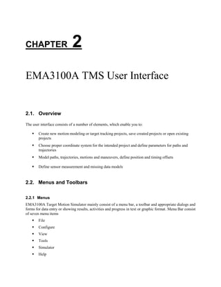
- 1. CHAPTER 2 EMA3100A TMS User Interface 2.1. Overview The user interface consists of a number of elements, which enable you to: Create new motion modeling or target tracking projects, save created projects or open existing projects Choose proper coordinate system for the intended project and define parameters for paths and trajectories Model paths, trajectories, motions and maneuvers, define position and timing offsets Define sensor measurement and missing data models 2.2. Menus and Toolbars 2.2.1 Menus EMA3100A Target Motion Simulator mainly consist of a menu bar, a toolbar and appropriate dialogs and forms for data entry or showing results, activities and progress in text or graphic format. Menu Bar consist of seven menu items File Configure View Tools Simulator Help
- 2. 9 File Menu consist of six items; New Open Close Save Save As Exit New item is for new project creation and Open item is used for opening a previously created TTP or MMP project Close item is used for closing an existing open project prompting user for Save the last project configuration.
- 3. 10 Chapter 2 EMA3100A TMS User Interface Save item is used for saving an existing open project with the latest current project configuration. Save As item is used for saving an existing open project with a different name and folder defined by the user. Exit item is used for closing down the EMA3100A Target Motion Simulator, by saving the current project configuration and deleting all temporary files.
- 4. 11 Configure Menu consist of two items Preferences Configuration Checker Preferences item is used to define user preferences for directories and files created, used and or deleted temporary files during execution of TTP and MMP projects or during use of standalone tools, Configuration Checker item is used to make configuration check upon completion of the configuration in TTP projects. View Menu consist of three items, Toolbar Status Bar EventsMonitor
- 5. 12 Chapter 2 EMA3100A TMS User Interface and all of them are used for either enabling or disabling the respective item view, Toolbar and Status Bar is checked and enabled by default EventsMonitor item is used to show EventsMonitor even if there is no ready event to be monitored for the project yet. Tools Menu consist of five items as; Path Modeler Path Combiner Trajectory Viewer SM Modeler MD Modeler and all of them are used to activate respective tool, Path Modeler item opens the Path Modeler dialog and Path Combiner Item opens the Path loader dialog.
- 6. 13 Trajectory Viewer item is used to open Trajectory Viewer to view and analyze paths or trajectories created by EMA3100A Target Motion Simulator or any other format converted logged recorded trajectory file. SM Modeler item is used to open SM Modeler tool which is used for modeling Sensor measurements in Target Tracking projects
- 7. 14 Chapter 2 EMA3100A TMS User Interface MD Modeler item is used to open MD Modeler tool which is used for modeling sensor missing data in Target Tracking projects Simulator Menu consist of two items Launch SimPanel Options… Launch SimPanel item shows the SimPanel if configuration is completed for a new or opened project, Options item opens a dialog for option checks. Help Menu consist of two items as, Contents About Contents item opens the chm Help file and About item shows the installation, license and version information of EMA3100A Target Motion Simulator
- 8. 15 2.2.2 Toolbar Toolbar consist of 11 items New Open Save Path Modeler Path Combiner Trajectory Viewer SM Modeler MD Modeler Configuration Checker SimPanel Help The first three item in toolbar are New, Open and Save, as described previously for File Menu items, New item is for new project creation and Open item is used for opening a previously created TTP or MMP project, Save item is used for saving an existing open project with the latest current project configuration.
- 9. 16 Chapter 2 EMA3100A TMS User Interface Next three items are Path Modeler, Path Combiner and Trajectory Viewer, Path Modeler item opens the Path Modeler dialog and Path Combiner Item opens the Path loader dialog. Trajectory Viewer item is used to open Trajectory Viewer to view and analyze paths or trajectories created by EMA3100A Target Motion Simulator or any other format converted logged recorded trajectory file. Next two items in Toolbar are SM Modeler and MD Modeler, SM Modeler item is used to open SM Modeler tool which is used for modeling Sensor measurements in Target Tracking projects. MD Modeler item is used to open MD Modeler tool which is used for modeling sensor missing data in Target Tracking projects
- 10. 17 Last three items in Toolbar are Configuration Checker, SimPanel and Help. Configuration Checker item is used to make configuration check upon completion of the configuration in TTP projects. SimPanel item shows the SimPanel if configuration is completed for a new or opened project and Help item opens the chm Help file. 2.3. User Preferences User Preferences form is used to define default directories to create and/or save relevant directories or files. There are two general (Projects Directory and Temporary Files Directory) and four project related (User SM Models Directory, User MD Models Directory, Default Outputs Directory and Log Directory) definitions.
- 11. 18 Chapter 2 EMA3100A TMS User Interface 2.4. Data Forms In this section we go through the forms used wither for user data entry or showing the data entry or results. 2.2.1 New Project Creation Form New Project Creation Form is used for selecting the project type (as one of Target Tracking project or Motion Modeling project), naming the project and locating the directory into which the project files are saved. To create a new project, select first project from Menu bar and then select New item from the Project menu as Project>New . Upon proper entry of required data, clicking OK opens the Project Data(MMP) form or Project Data(TTP) form depending on the chosen project type. 2.2.2 Project Data (MMP) Form Project Data (MMP) Form is used for selecting the coordinate system for Motion Modeling projects (if the chosen project type is Motion Modeling Project). Upon selection of intended coordinate system for the created project clicking OK opens Motion Modeler form.
- 12. 19 2.2.3 Motion Modeler Form Motion Modeler Form is used for naming the target or item for which the motion is modeled, defining the Sampling Time in seconds and selecting the method of motion modeling. Upon naming the target, entering the sampling time and selecting the method of motion modeling, clicking Edit opens the Path Modeler form in proper coordinate system chosen in previous step by using Project Data (MMP) form. 2.2.4 Path Modeler (TMM-Cartesian) Form Path Modeler (TMM-Cartesian) form is used for creating/adding paths for the trajectory to be modeled and modeling each path independently if the chosen coordinate system is Cartesian 2D/3D. The left pane of the form is used for adding paths by right clicking on the Trajectory Segments and modeling those added paths after selecting the path by first left click to select and then right clicking on the chosen path and selecting Model the Path menu item, which opens Path Editor (TMM-Cartesian). The right pane of the form basically shows the parameters of the model entered in Path Editor.
- 13. 20 Chapter 2 EMA3100A TMS User Interface 2.2.5 Path Editor (TMM-Cartesian) Form Path Editor (TMM-Cartesian) form is used for entering parameters of the model and method for the chosen path. Depending on the Motion Modeling method, some parts of the form is available for data entry and some others are not, details of Motion Modeling methods are provided in Chapter 6, Using EMA3100A TMS Tools. 2.2.6 Path Modeler (TMM-Polar) Form Path Modeler (TMM-Polar) form is used for creating/adding paths for the trajectory to be modeled and modeling each path independently if the chosen coordinate system is Polar. The left pane of the form is used for adding paths by right clicking on the Trajectory Segments and modeling those added paths after selecting the path by first left click to select and then right clicking on the chosen path and selecting Model The Path menu item, which opens Path Editor (TMM-Polar). The right pane of the form basically shows the parameters of the model entered in Path Editor.
- 14. 21 2.2.7 Path Editor (TMM-Polar) Form Path Editor (TMM-Polar) form is used for entering parameters of the model and method for the chosen path. Depending on the Motion Modeling method, some parts of the form is available for data entry and some others are not, details of Motion Modeling methods are provided in Chapter 6, Using EMA3100A TMS Tools. 2.2.8 Path Combiner (TMM-Cartesian/Polar) Form Path Combiner (TMM-Cartesian/Polar) form is used for combining previously created paths to form a single trajectory as combination of those paths, where this combination is completely determined by the user choices. Details of Path Combiner are provided in Chapter 6, Using EMA3100A TMS Tools.
- 15. 22 Chapter 2 EMA3100A TMS User Interface 2.2.9 Path Loader Form Path Loader form is used to load previously created paths when Path Combiner is used as a standalone tool. Details of Path Combiner are provided in Chapter 6, Using EMA3100A TMS Tools. 2.2.10 Trajectory Viewer Selection Form Trajectory Viewer selection form is used to load previously created paths and to select the proper coordinate system when Trajectory Viewer is used as a standalone tool. Details of Trajectory Viewer are provided in Chapter 6, Using EMA3100A TMS Tools.
- 16. 23 2.2.11 Project Data (TTP) Form Project Data (TTP) Form is used for selecting the coordinate system for Target Tracking projects (if the chosen project type is Target Tracking Project). Upon selection of intended coordinate system for the created project clicking OK opens Target Configuration-Cartesian Domain or Target Configuration-Polar Domain form depending on the chosen coordinate system. 2.2.12 Target Configuration-Cartesian Domain Form Target Configuration-Cartesian Domain form is used for creating/adding targets and configuring parameters for each target independently if the chosen coordinate system is Cartesian 2D/3D. The left pane of the form is used for adding targets by right clicking on the Target(s) item and configuring those added targets after selecting the target by first left clicking to select and then right clicking on the chosen target and selecting Configure Target menu item, which opens Target Configuration form. The right pane of the form basically shows the parameters of the target entered in Target Configuration form.
- 17. 24 Chapter 2 EMA3100A TMS User Interface 2.2.13 Target Configuration-Polar Domain Form Target Configuration-Polar Domain form is used for creating/adding targets and configuring parameters for each target independently if the chosen coordinate system is Polar. The left pane of the form is used for adding targets by right clicking on the Target(s) item and configuring those added targets after selecting the target by first left clicking to select and then right clicking on the chosen target and selecting Configure Target menu item, which opens Target Configuration form. The right pane of the form basically shows the parameters of the target entered in Target Configuration form. 2.2.14 Target Configuration Form Target Configuration form is used for entering parameters of the target selected, which are sampling time and activation offset, initial position offset values for each coordinate axis, sensor measurement model, missing data model and trajectory for the selected target. Details of Target Tracking projects are provided in Chapter 5, Target Tracking Projects.
- 18. 25 2.2.15 Configuration Check Form Configuration Check form is used in Target Tracking projects for checking consistency of configuration and entered parameters, done upon completion of target configuration stage by clicking Conf Check button on Target Configuration-Cartesian Domain or Target Configuration-Polar Domain depending on the project coordinate system chosen in previous stages. 2.2.16 SimPanel Form SimPanel form is used for informing user about the execution of simulation steps, depending on the Options selected writes output files to defined locations and launches GraphPanel for created output plots, as detailed in Chapter 5, Target Tracking Projects.
- 19. 26 Chapter 2 EMA3100A TMS User Interface 2.2.17 GraphPanel (TMM-Cartesian 2D) Form GraphPanel (TMM-Cartesian 2D) form is used for presenting output plots for 2D Cartesian coordinate system projects (initiated by Motion Modeling Projects, Target Tracking projects or standalone tools like Path Modeler, Path Combiner or Trajectory Viewer). Details including zoom, pan, rotation functionalities and selections for static and animated plots are provided in Chapter 7, GraphPanel and Graphics. 2.2.18 GraphPanel (TMM-Cartesian 3D) Form GraphPanel (TMM-Cartesian 3D) form is used for presenting output plots for 3D Cartesian coordinate system projects (initiated by Motion Modeling Projects, Target Tracking projects or standalone tools like Path Modeler, Path Combiner or Trajectory Viewer). Details including zoom, pan, rotation functionalities and selections for static and animated plots are provided in Chapter 7, GraphPanel and Graphics.
- 20. 27 2.2.19 GraphPanel (TMM-Polar) Form GraphPanel (TMM-Polar) form is used for presenting output plots for Polar coordinate system projects in Range-Azimuth, Range-Elevation and Azimuth-Elevation (initiated by Motion Modeling Projects, Target Tracking projects or standalone tools like Path Modeler, Path Combiner or Trajectory Viewer). Details including zoom, pan, rotation functionalities and selections for static and animated plots are provided in Chapter 7, GraphPanel and Graphics. 2.2.20 Sensor Measurement Model Form Sensor Measurement Model form is used for modeling the sensor measurements in Target Tracking projects, and provides selection of random distribution and second order characterization along with time dependency in terms of frames for selected frame lengths. Details of sensor measurement models are provided in Chapter 5, Target Tracking Projects.
- 21. 28 Chapter 2 EMA3100A TMS User Interface 2.2.21 Missing Data Model Form Missing Data Model form is used for modeling the missing data in Target Tracking projects, and provides selection of random distribution and second order characterization along with time dependency in terms of frames for selected frame lengths. Details of missing data models are provided in Chapter 5, Target Tracking Projects.