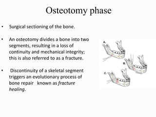
4. • Distraction osteogenesis of the craniofacial skeleton
has become increasingly popular as an alternative to
many conventional orthognathic surgical procedures.
• For patients with mild to severe abnormalities of the
craniofacial skeleton, distraction techniques have
increased the number of treatment alternatives.
Introduction
5. DEFINITION
Distraction osteogenesis is a biological process of
new bone formation between vascularised margins
of bone segments when they are gradually separated
by an incremental traction.
6. • In 1905 Codivilla performed first bone distraction- femur.
• In 1927, Abbott applied this same concept to the lengthening
of a tibia.
• Rosenthal applied it in maxillofacial region. However, because
of a high complication rate that included skin infection, tissue
necrosis, and the unpredictable reossification of the expanded
bone, distraction osteogenesis did not initially gain clinical
acceptance.
History
7. • In 1954, ILIZAROV began his work on the lower extremity.
• He was a Russian orthopedic surgeon who began using
techniques that combined compression, tension, and then
repeat bone compression to heal fractured long bones with
segmental defects.
• Based on his work in these patients, he pioneered the radical
concept that bone generation could be initiated by the
piezoelectric effect of tension , rather than compression.
• Ten to 15 year later, he expanded his technique to include
the treatment of shortened lower extremities.
8. • Distraction osteogenesis remained a long-bone treatment till
1972, Snyder et al used a Swanson external fixator to lengthen
a canine mandible.
• He surgically shortened one side of the mandible by removing
a 1.5 cm segment and then allowed the bone to heal.
• This created a large crossbite that was surgically corrected 10
weeks later by attaching an external fixator, performing an
osteotomy, and then slowly expanding the device until the
crossbite was normalized.
9. • In 1975, Bell & Epker Described a technique of rapid
palatal expansion to increase the maxillary width in
cases of transverse deficiency, using a Haas appliance.
• In 1976 Michieli and Miotti reproduced Snyder's work,
using an intraoral device.
10. Indications
• Unilateral & Bilateral craniofacial microsomia
• Developmental micrognathia
• Treacher Collins syndrome, Pierre Robin syndrome.
• Midface hypoplasia (craniofacial synostosis syndromes)
• Transport distraction has been shown to be a useful
technique for the regeneration (Newly forming bone) of the
mandibular condyle
11. • Tocorrect mild skeletal Class II
• To expand the mandibular symphysis to skeletally correct
lower anterior crowding.
• Condylar hypopolasia
• Post-traumatic growth disturbance
• Aid for ridge augmentation
12. Contraindications
• Poor nutrition and lack of soft tissue
• Inadequate bone stock as in neonates
• Geriatric patients due to decreased number of mesenchymal stem
cells and repair
• Irradiated bone
• Osteoporotic bone
• Any systemic disease which effects bone metabolism or
contraindicated general anesthesia.
13. Advantages
• Need for orthognathic surgery is minimised and so are the
complication associated with orthognathic surgery.
• Shorter hospital stay
• Less likelihood of nerve injury
• Reduced need for intermaxillary fixation
• Reduced postoperative pain and swelling
• Less likelihood of idiopathic condylar resorption
• Greater range of maxillary advancement is possible.
14. • Cleft patients with maxillary hypoplasia distraction process is less
likely to adversely affect the speech.
• Greater range of mandibular advancement is possible.
• New bone formed via distraction osteogenesis is more native
and permits orthodontic tooth movement.
• Allows complete bone sculpting i.e. changing the shape and
form of bones to maximise the 3D structural, functional and
aesthetic needs of the patient.
15. Disadvantages
• Daily manipulation of Corticotomy one or several times a day
could give rise to pain.
• Difficult access for the orthodontist during distraction and
consolidation stages as the distractor could obscure the
buccal segments.
• Difficult plaque control
16. • Damage to TMJ due to incorrect vector orientation
• Technique sensitive surgery
• Equipment sensitive surgery
• High cost of distraction appliance
• Need for second surgery to remove distraction
device
17. Biology of distraction
• Distraction as a technique is divided into two
categories, depending on the anatomic site.
• The predominant method of distraction in maxillofacial
applications is callotasis, or distraction of the healing callus
between bone fragment after a Corticotomy or osteotomy.
18. Ilizarov discovered two biologic principles of
known as the "ilizarov effects"
(1) The tension-stress effect on the genesis and growth of
tissues, and
(2) The influence of blood supply and loading on the shape
of bones and joints.
19. The first Ilizarov principle postulates that gradual traction
creates stress that can stimulate and maintain
regeneration and active growth of living tissues.
• Clinically, after distraction, newly formed bone rapidly
remodels to conform to the bone's natural structure.
20. The second Ilizarov principle theorized that the shape
and mass of bones and joints are dependent on an
interaction between mechanical loading and blood
supply.
• If blood supply is inadequate to support normal or
increased mechanical loading, then the bone cannot
respond favorably, leading to atrophic or degenerative
changes.
21. Phase of distraction osteogenesis
ď‚— Clinically, Distraction osteogenesis consists of five
sequential periods:
(1) Osteotomy
(2) Latency, the duration from bone division to the onset of
traction;
(3)Distraction, the time when gradual traction is applied
and distraction regenerate is formed;
22. (4) Consolidation, the period that allows maturation and
corticalization of the regenerate after traction forces are
discontinued and
(5) Remodeling which extends from the initial application of full
functional loading to the completion of regenerate bone remodeling.
23. Osteotomy phase
• Surgical sectioning of the bone.
• An osteotomy divides a bone into two
segments, resulting in a loss of
continuity and mechanical integrity;
this is also referred to as a fracture.
• Discontinuity of a skeletal segment
triggers an evolutionary process of
bone repair known as fracture
healing.
24. • This process involves recruitment of osteoprogenitor cells,
followed by cellular modulation or osteoinduction, and
establishment of an environmental template (osteoconduction).
• As a result, a reparative callus is formed within and around the
ends of the fractured bone segments; under normal conditions,
the callus undergoes gradual replacement by lamellar bone, which
is mechanically more resistant.
25. ď‚— Traditionally fracture healing has been described as
consisting of six stages or phases
(1) Impact,
(2) Induction,
(3) Inflammation,
(4) Soft callus,
(5) Hard callus, and
(6) Remodeling
26. • Osteotomy for DO should aim for maximum preservation of
periosteum and endosteum to maintain an intact blood supply, good
venous flow and viable source of cell required in order to initiate and
perpetuate the distraction osteogenesis process.
27. Latency phase
• It is characterised by initial inflammation followed by
formation of soft callus, hard callus and calcification leading to
bony union.
• If distraction is begun too early, the result is decreased bone
formation, often with cartilaginous elements present and
decreased mechanical strength of the newly created bone.
• If distraction is begun too long(i.e, if hard callus formation has
begun) the distraction device may be unable to further
separate the bone segments.
28. • The soft tissue callus phase begins 3 to 7 days after injury
and lasts 2 to 3 weeks; this time frame set the boundaries of
latency period.
• Distraction in the maxillofacial skeleton has been reported
with immediate activation and with latency phases of up to
12 day.
29. Distraction phase
ď‚— After latency period , tension is placed on the bony
segment by activating the appliance.
30. ď‚— Two important variable in the activation
1. Rate: Amount of distraction per day
2. Rhythm: How frequently the devices is activated
• Rate 1.0 mm per day
Small
Great
risk of pre mature consolidation
undue stress on soft callus resulting in
thinning of all
dimension in
midportion of
regenerate and an “
hourglass” at
distraction site
31. Rhythm
• Continuous application of distraction force is ideal
• Clinically, application of the distraction is best performed by
activating the device twice a day(0.5 mm twice a day)
• If the patient experiences discomfort ,then the rhythm
should be altered to allow for a smaller incremental
application(0.25 mm for four times a day)
32. Radiographic and schematic drawing demonstrating five zonal structure
of distraction regenerate. Radiolucent fibrous interzone(FZ); Radiodense
mineralizing zone(MZ); Radiolucent zone of remodeling(RZ); Residual
host bone segments(RHBS).
33. Consolidation phase
cessation of traction forces and removal
ď‚— The consolidation period is that time between
of the
distraction device.
ď‚— This period represents the time required for complete
mineralization of the distractionregenerate.
ď‚— After distraction ceases, the fibrous interzone gradually
ossifies and one distinct zone of fiber bone completely bridges
thegap.
34. Radiograph and schematic drawing demonstrating structure of
distraction regenerate during consolidation period. Radiolucent zone of
remodeling(RZ) adjacent to the residual host bone segments(RHBS) and
divided by the mineralization zone (MZ).
35. • The total amount of bone formation seen in different type of
regenerate varies, but the final percentage of trabecular bone
increased from the end of distraction through 8 weeks of
consolidation.
• Mineralization began at the host bone margins at the end of
distraction and progressively increased up to the fourth week of
consolidation, at which time it remained stable for the following
2 weeks.
• This decreased slightly from 6 to 8 weeks of consolidation, as
remodeling became the predominant activity of the regenerate.
36. Remodelling
• The remodeling period is the period from the application of
full functional loading to the complete remodeling of the
newly formedbone.
• It takes a year or more before the structure of newly formed
bony tissue is comparable to that of the pre-existing bone.
• Generally the regenerated segments of bone show a
relatively low mineral content and radiodensity.
37. Schematic drawing demonstrating structures of distraction regenerate during
remodeling period. Gradual corticalization of the remodeling zone (RZ) with
formation of medullary canal (MC)is seen. RHBS, Residual host bone
segment; CB, Cortical Bone.
39. Distraction appliances of the maxillofacial region can
be divided into:
Extra-oral appliances
• Unidirectional devices
• Bi-directional devices
• Multidirectional devices
41. External unidirectional distraction devices
• In 1992, McCarthy et al introduced an
external unidirectional distractor to
successfully lengthen the mandible
unilaterally and bilaterally.
• The amount of distraction varied from
18 mm to 24 mm .
• The distractor consisted of a single
calibrated rod with two clamps .
• Each clamp holds two 2 mm half pins
that are placed on either side of the
osteotomy.
42. • Approximately 20 mm to 24 mm of bone stock posterior to
the last tooth bud is necessary to place this device.
• By turning the bolt at the end of the rod ,the distance
between the clamps can be changed to provide expansion or
compression at the level of the bone.
43. Molina Distractors
• Ortiz & Molina modified the Ilizarov technique by performing an
incomplete corticotomy.
• They left the internal cortical plate and the cancellous layer intact &
used a semi rigid external distractor.
44. • This has the capability to further exploit the
secondary soft tissue expansion associated with
osteodistraction.
• Molina distractors are unidirectional, changes in
the three dimensions have been documented.
45. Disadvantages
• Scarring as a result of pins dragging through the skin
during expansion
• Difficulty predicting the direction in which the
distraction wouldproceed
• Inability to change direction once distraction process
had begun
46. External bidirectional distraction
• A bidirectional distraction appliance provides an additional degree
of freedom over the unidirectional device.
• Klein & Howaldt developed an external bi-directional device
capable of achieving controlled changes in angulation.
47. • The device consists of two geared arms 5 cm in
length connected to a middle screw that enables
the arms to be moved up or down to change
angulations.
48. Multiplanar distraction
• The ability to make transverse changes was the final step in achieving
three dimensional control.
• McCarthy et al reported their experience using an external
multiplanar device to correct the asymmetry in a child with unilateral
craniofacial microsomia.
49. ď‚— The multiplanar device consists of a central housing with
two work gears in different planes .
ď‚— Two arms extend from the housing with pin clamps at either end.
ď‚— Each quarter turn of the wheel results in 0.25 mm of expansion.
ď‚— Two activation screws enable changes in the transverse and
vertical angulations.
50. Internal distractors
• In 1995, McCarthy et al introduced an intraoral distraction
appliance tested on the canine model.
• After osteotomy , the device was placed on the buccal
surface of the mandible and the lengthening rod was
extended into the buccal vestibule.
• A drawback of the appliance was that it could only
accommodate 20 mm of expansion.
51. • Vasquez and Diner, developed two internal
distractors , for lengthening the mandibular body and
the ramus.
52. Tooth borne intra oral distractor
• In 1997, Razdolsky et al introduced a completely tooth-borne
intraoral distractor capable of making linear changes.
• Current technique starts by fitting preformed stainless steel
crowns to one tooth on either side of the anticipated
osteotomy site( usually the second M & first PM teeth)
53. Symphesial Distraction
• For V shape mandible
• Severe mandibular crowding
• Brodie's syndrome
• To avoid inderdental stripping or extractions
54. Vector of DO: Biological and Mechanical
ď‚— The biological and mechanical forces that shape the
regenerate (the newly formed bone during the active period
of distraction osteogenesis) are key elements in determining
appliance position.
ď‚— The desired mandibular change in shape and function can be
achieved by selecting and controlling the force vectors that
operate during active distraction.
55. • The biological forces influencing the morphology of the bone
regenerate (newly formed bone) arise from the surrounding
neuromuscular envelop.
56. • The mechanical forces under the clinician's control originate
from activation of the distraction devices, their specific
orientation to skeletal anatomy, the application of
intermaxillary elastics during the active phase of distraction,
and the intercuspation of the dentition.
• It is important to note that the position of the device is best
described in relation to the long axis of the mandibular body.
57. Vectors of distraction:Straight lines indicate the long axis of the device.
• Vertical (A), horizontal (B), and oblique (C).
• The line represents the long axis of the
device in relation to the long axis of the
mandibular body.
• In this planning method, the authors do
not orient the device in relation to the
posterior border of the ramus or the
inferior border of the mandible because of
the variability in morphology of these
borders.
58. Vertical device placement
• Vertical device placement results in an increase in the vertical
dimension of the mandibular ramus.
• During activation, a change occurs in appliance orientation
that appears to be caused by the nonlinear molding effect of
the neuromusculature on the regenerate as it is formed.
• The mandible autorotates in a counterclockwise direction,
and the lower incisors take a more advanced position.
• A posterior open bite may occur on the side that has
undergone vertical distraction in the ramus
59. The device placed vertically in the mandibular ramus before
activation (A).
Activation of the device results in an increase in the vertical
height of the ramus.
Note the separation between the maxillary and mandibular
dentition before closure of the mandible (B).
60. • The mandible autorotates in a counter- clockwise direction, the lower incisors take
a more advanced position, and a posterior open bite may present itself on the side
that has been lengthened vertically (C).
• Note that bilateral vertical lengthening of the ramus is associated with
counterclockwise up- righting of the symphysis.
• This, along with sagittal advancement of the mandibular body, contributes to the
perception of increased prominence of the lower third of the face (D).
61. Horizontal device placement
• The most efficient approach for achieving sagittal
projection of the mandibular body and symphysis is by
placement of the distraction device in a horizontal
position in relation to the mandibular body.
62. • Horizontal device placement results in an increase in the
anteroposterior dimension of the mandibular body with
increased sagittal projection of the symphysis (A,B).
63. • There is a tendency in horizontal distraction for the body to rotate in a
clockwise direction, sometimes resulting in open bite.
• The pull of the suprahyoid musculature may have a role in this
occurrence.
• There has been a reported improvement in patency of the
oropharyngeal airway and tongue position subsequent to mandibular
sagittal advancement
64. Oblique device placement
ď‚— Oblique device placement results in an increase in
both the vertical and horizontal dimensions of the
ramus and body. The effect
placement is a combination
of oblique device
of the vertical and
horizontal change.
• Overjet and both ramal and
body size deficiency may be
addressed by oblique device
placement.
65. MAXILLARY DISTRACTION
• Surgical approach is similar to conventional Lefort l osteotomy.
• Maxilla is freed but not completely down-fractured, 2-0 poly
diaxone suture at the maxillary 1st molar and zygomatic buttress to
prevent the posterior tipping.
• Device is pre-bend for the placement
• Ideal trajectory – distraction parallel to each other and to the mid
sagittal plane.
• Anterior elastics to guide maxilla to proper position is used.
66. Maxillary DO hypoplastic maxilla.
(a) Application of internal distractor device following osteotomy.
(b) Distracted maxilla in AP direction.
67. MAXILLARY SEGMENTAL DISTRACTION
ALVEOLAR CLEFTS
Lesser osteotomy-
between
premolars and 1st
molars
Greater osteotomy-
between incisors
and cuspids
Use of orthodontic appliances and
arch wires allows the distraction
segments to follow the curvature
of maxillary arch
68. • After distraction, orthodontic spring paralleling to the
regenerate chamber 1-2 weeks after distraction
ossification is used.
• Orthodontic alignment , repositioning of teeth in the
regenerate chamber leaving the defect for implant
surgery if required small grafting will be done
• This is a form of transport DO
69. COMBINED MAXILLARY & MANDIBULAR
DISTRACTION OSTEOGENESIS
• Mandibular elongation by gradual distraction in
patients with hemifacial microsomia is a simple and
effective procedure to correct facial asymmetry.
• The changes in mandibular dimension result in
changes in dental occlusion.
• These are minimal in children because of the rapid
growth of the maxilla and can be corrected easily
with minor orthodontic treatment.
70. • Mandibular distraction in adults with hemifacial
microsomia produces good aesthetic results but
leaves the patient with a severe alteration in the
occlusion requiring complex orthodontic treatment
over a long period of time.
• To avoid this problem, an incomplete Le Fort I
osteotomy is performed simultaneously with the
mandibular Corticotomy.
ď‚— Intermaxillary fixation is placed on the fifth
postoperative day, and distraction is initiated.
71. • After distraction, both the maxillary and mandibular
occlusal planes become horizontal, and facial
asymmetry is corrected.
• There is a reduction in treatment time and cost when
compared with the protocol of mandibular distraction
followed by passive bite plate guiding the eruption of
the maxillary posterior occlusal plane
72. • A, Complete maxillary LeFort I (dashed line), unilateral horizontal ramus
osteotomy; mandibular buried single-vector distractor; intermaxillary wire fixation
(dotted line); single wire acting as a hinge (circle , contralateral side); vertical and
curved arrows indicate the expected direction of the maxillary and mandibular
movements after distraction.
• B, Expected vertical bone formation between osteotomies, downward and medial
rotation of the maxilla and mandible to the contralateral side with leveling of the
occlusal plane and restoration of symmetry.
73. • The process of slow bone expansion by distraction osteogenesis in
conjunction with functional remodeling can also be used for the
reconstruction of a neomandible and neocondyle. This is the
technique of transport distraction osteogenesis.
Reconstruction of a Neocondyle Using
Transport Distraction Osteogenesis
74. • Transport distraction osteogenesis is the technique of
regenerating bone and soft tissues in a discontinuity
defect.
• Osteotomy is made 1.5 cm from the end of the distal
stump of bone adjacent to the discontinuity defect
creating a transport disc.
75. • Using a distraction device, the transport disc is
advanced through the soft tissue discontinuity defect,
creating new bone within the distraction gap, as the
leading edge becomes enveloped by a
fibrocartilagenous cap.
Three points of fixation are necessary for
transport DO
1. Proximal stump
2. Distal side
3. Transport disc
Or use a rigid connector with conventional
distractor
2
3
1
76. • The mandible therefore acts as the bony template for
reconstruction such that the neomandible created
from the distraction process has the same size and
shape as the native mandible covered by gingiva.
This allows for enhanced prosthetic reconstruction.
77. • The transport disc is created from the ramus by
making a reverse-L osteotomy extending from the
sigmoid notch to 1 cm above the inferior border ,
preserving the angle of mandible. This transport disc
is now advanced superiorly 0.5 mm twice a day
78. • Because the leading edge of the transport disc
becomes enveloped by a fibrocartilagenous cap, the
ramal transport disc can be moved superiorly to
create a new articulation.
• Patients are encouraged to open and close their
mouths during the distraction process, such that the
transport disc remodels to form a neocondyle.
• This technique was successfully used to treat patients
with degenerative joint disease, condylar resorption,
and bony ankylosis.
79. Alveolar Distraction Osteogenesis
• In deficient alveolar bone height for implant placement, DO
could increase bone level up to 16 mm at the rate of 1 mm
per day.
• However, comprehensive assessment is required in a
severely resorbed ridge as minimal thickness for both basal
and transport segment are necessary for the fixation of the
distractor plates.
• It is also very important to ensure the lingual or palatal
mucosa remains intact to the transport segment for
vascularization.
80. Alveolar DO for atrophic mandibular anterior ridge.
(a)Application of internal device for vertical distraction.
(b)New height of distracted alveolar ridge.
81. treatment possibilities.
ď‚— Distraction expands the scope for correction
but requires careful planning and execution.
ď‚— DO has replaced orthognathic surgery to some
extent and indeed redefined the envelop of
discrepancy.
ď‚— Craniofacial deformities are complex and require
careful evaluation.
ď‚— The deformity may impose limitations on the
CONCLUSION
82. References
• Grayson B, Santiago PE: treatment planning and biomechanics of distraction
osteogenesis from an orthodontic perspective.
• Kharbanda OP, orthodontics diagnosis and management of malocclusion and
dentofacial deformities, 2nd edition
• McCarthy, Stelnicki and Grayson, DO of the mandible: A ten year experience, Vol 5,no
1 ,march 1999, PP 3-8
• Guerrero et al, Intraoral mandibular DO,Vol 5,no 1 ,march 1999: PP 35-40
• Proffit, white, Sarver: contemporary treatment of dentofacial deformity
• Harsh Mohan , textbook of pathology, 6th edition
• Deirdre J. Maull, Review of devices for DO of the craniofacial complex , PP 64-73
• Fernando Molina , combined maxillary & mandibular distraction osteogenesis,
1999;5:41-45.
• Suzanne u. Stucki-McCormick, Robert M. Fox and Ronald D. Mizrahi , reconstruction
of a neocondyle using transport distraction osteogenesis , 1999;5:59-63.