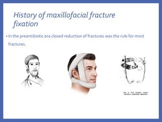
2. CONTENTS
• History
• Aims of fracture fixation
• Biological reaction and healing of bone
• Biomechanics of facial skeleton
• Concepts in fracture fixation
• Fixation systems for closed reduction
• Fixation systems for open reduction
• Advances in fixation systems
• Complications of fixation of fractures
3. History of maxillofacial fracture
fixation
• In the preantibiotic era closed reduction of fractures was the rule for most
fractures.
4. • Gilmer reintroduced intermaxillary fixation by wiring in US in 1887
• Most of the nondental fixation techniques used during that time took
the form of pins inserted transcutaneously into the mandible and
connected externally by a variety of devices
5. • Following the development of antibiotics, the open treatment of fractures began
to be used on a more frequent basis
• Buck -first to place an intraosseous wire in a mandibular fracture in 1847
• Adams in 1942 popularised the use of internal wire fixation
To overcome the lack of stability at the fracture site provided by intraosseous
wiring, more rigid hardware was applied to mandibular fractures.
• Intramedullary pinning, first advocated by Major in 1938 was extensively used
by McDowell et al for maxillofacial fractures
Ref : Ellis E. Rigid skeletal fixation of fractures. Journal of Oral and Maxillofacial Surgery. 1993;51(2):163-173.
6. • The surgeon Hansmann (1886) was the first to develop and present a
procedure for subcutaneous fixation of bone fragments with a plate screw-
system.
• Up to 1886, Hansmann had treated 21 bone fractures and pseudarthroses
with this method.Two of these were mandibular fractures making him the
first to perform a plate osteosynthesis on the mandible.
• Lambotte (1907)-established the term osteosynthesis
. Ref : Sauerbier S, Schön R, OttenJ, Schmelzeisen R, Gutwald R.The development of plate osteosynthesis for the treatment of
fractures of the mandibular body – A literature review.Journal of Cranio-Maxillofacial Surgery. 2008;
7. History of Bone plating
• Compression plating
Luhr introduced ‘‘compression osteosynthesis’’ of the mandible
In 1969, the AO/ASIF introduced a Dynamic Compression Plate (DCP) for limb
surgery
8. Spiessl modified these plates to match the dimensions of the mandible
and applied them clinically
The plates modified by Niederdellmann and Schilli (1972, 1973) possessed
two holes located close to the fracture gap for screws to build up axial
pressure – Eccentric Dynamic Compression Plates
9. • Lag screws
First introduced to maxillofacial surgery by Brons and Boering in 1970,
who cautioned that at least two screws are necessary to prevent
rotational movement of the fragments in oblique fractures of the
mandible
10. • Reconstruction plates
Raveh et al. (1987) introduced a reconstruction plate system made of
titanium which enabled the heads of the screws to lock into the holes of
the plate-THORP(Titanium-coated Hollow Screw and Reconstruction
Plate System)
A similar, but smaller reconstruction plate was developed in the mid
1990s by the AO/ASIF, the UniLOCK 2.4 (Universal Locking Plate).
11. Miniplate osteosynthesis
• Small finger plates, originally utilized in hand surgery, were inserted for
mandibular fractures by Brons and Boering (1970).
• Michelet et al. (1973) applied vitallium miniplates in more than 300
mandibular fractures. He placed the material along the tensile trajectories and
inserted monocortical screws to avoid injury to the tooth roots.
Postoperatively, mandibulo-maxillary immobilization was not necessary in
most cases.
• Champy et al. (1975, 1976, 1977, 1978) modified this method to make it
clinically more applicable-outlined the zones of Ideal osteosynthesis
12. Aims of fracture fixation
•Restore anatomical relationship
•Absolute or relative stability
•Preservation of blood supply
• Early and safe mobilization
13. Biological reaction and healing of fractures
Primary or direct bone union
• Interfragmentary stability
Contact healing –
Direct apposition of cortical bone surfaces
Haversian remodelling occurs in bone contact
areas-histologically, osteoclasts cross the
fracture gap and are followed by blood vessels
and osteoblasts
14. Gap healing
• New bone is laid down by the osteoblasts,
forming osteons which cross the gap and impart
microscopic points of bony union to the fracture.
• Remodelling phase then converts the entire area
to morphologically normal bone.
• Small gaps between the bone fragments heal by
deposition of lamellar bone in a direction parallel
to fracture surface
15. Secondary or Indirect bone union
Interfragmentary mobility present- Non-rigid fixation
Characterised by formation of periosteal and endosteal callus
Between the fractured segments, a tissue differentiation cascade takes place
Stiffness and strength increases until the interfragmentary space is completely
ossified
17. Biomechanics of maxillofacial skeleton
Mandible
• Curved beam acting as a Class III lever with
condyle acting as fulcrum, masticatory
muscles as applied forces and bite load as
resistance force
18. • Zones of compression and tension within the fractured mandible are
determined by the muscles inserting onto the mandible and the forces
exerted by these muscles during function
• Stress points also vary according to the bite location
19. Angle region
• the angle under most functional situations tend to “open” at the superior
border
• Therefore, the application of fixation devices at the superior border is more
effective in preventing this separation of fragments under function than
applying them at the inferior border
20. Body region
• More anterior the fracture, the more tendency for torqueing of the
fragments to occur, causing mediolateral misalignment of the inferior
border.
• Load posterior to the fracture line results in compression at superior margin
and tension at inferior margin
• Loads anterior to the line will lead to reversal of stress patterns
21. Anterior symphysis region
• Anterior mandible undergoes shearing and torsional (twisting) forces
during functional activities
• There is no muscle support in midline region, compressive stresses in
upper and tensile stresses at lower margin
22. • Champy’s ideal osteosynthesis lines (1976): correspond to neutral zones
along which plate can be fixed for favourable stress patterns
• Miniplates placed along these osteosynthesis lines restored the stress
patterns across the mandible – providing adequate stability
24. • Soft tissue contraction of masseter sling develops equal forces at the origin
and insertion with stresses distributed differentially due to significant
difference in geometry of midface and geometry
• Frontozygomatic receives greatest tensile forces and is the strongest pillar of
the zygomatic complex- important point of fixation
25. Implications for biomechanics of internal
fixation
fixation of fractures done for
•Restoration of tension and pressure trajectories
•Neutralization of functional stresses developing in the bone
26. Concepts in Fracture fixation
•Direct vs Indirect fixation
•Rigid vs Non-Rigid fixation vs semi-rigid fixation
•Compression vs non-compression osteosynthesis
•Load bearing vs load sharing osteosynthesis
27. Direct vs indirect fixation
•Direct fixation- fracture fixation implant placed directly across the
fractured segments after surgical exposure of the fracture site.
•Examples –interosseous wiring, bone plating, lag screws
•Indirect fixation- adjacent structures used as anchorage to
immobilise the fractures fragments in anatomical position
•Examples – dental wiring for maxillomandibular fixation, internal
skeletal suspension, cap splints, gunning splints
28. Rigid versus Non-rigid fixation
Rigid fixation
•any form of fixation applied directly to the bones which is
strong enough to prevent interfragmentary motion across the
fracture when actively using the skeletal structure.
•To rigidly stabilize fractures, an operative procedure is
necessary
•Fractures undergo healing by primary or direct union
29. Indications of rigid fixation
Fracture in atrophic edentulous mandible
Concomitant fractures of the body and condyle when early
mobilization is required
Continuity defects
Non-union or malunion
30. • Examples of rigid fixation
Large compression plate in combination with arch bar
Two bone plates for mandibular fractures
Two lag screws inserted across a symphysial fractures
31. Non-rigid fixation
•There is mobility of the osseous fragments during active use of
the skeletal structure following application of internal fixation
devices.
•Only partial stabilization of bone fragments, torsional or shear
stress not neutralized
•Additional form of fixation like IMF is usually required
•Examples – inter-osseous wiring
33. Semi-rigid or Functionally stable fixation
•Form of nonrigid fixation that are strong enough to allow active
use of the skeleton during the healing phase but not of sufficient
strength to prevent interfragmentary mobility.
•Adequate stability to allow function
•Example
34. Load bearing vs Load sharing osteosynthesis
Load bearing fixation
• Load-bearing fixation is a device that is of sufficient strength and rigidity that
it can bear the entire load applied to the mandible during functional activities.
Indications
• Comminuted fractures of the mandible,
• Those fractures where there is very little bony interface because of atrophy
• Those injuries that have resulted in a loss of a portion of the mandible (defect
fractures)
35. •The most commonly used load-bearing device is a mandibular
reconstruction bone plate (relatively large, thick, and stiff)
•When secured to the fragments on each side of the injured area
by a minimum of three bone screws, reconstruction bone plates
can provide temporary stability to the bone fragments
36. Load sharing osteosynthesis
•Insufficient stability to bear all of the functional loads applied
across the fracture by the masticatory system
•Requires solid bony fragments on each side of the fracture that
can bear some of the functional loads
•Indicated for simple linear fractures without any bony defect
•2mm miniplate systems,
• Lag screw techniques
37. Factors to be considered when selecting a fixation scheme for a given
fracture-
•Fracture pattern
•Condition of the bone
•Amount of soft tissue disruption necessary to expose the fracture
and place the fixation devices.
•Medical condition of the patient
•Skill of operator
38. Methods of fixation
• Closed reduction and Indirect Fixation
• Open reduction and Direct Fixation
43. Maxillomandibular screw fixation
• Mandibulo-maxillary fixation (MMF) screws are
inserted into the bony base of both jaws in the
process of fracture realignment and
immobilisation.
• The screw heads act as anchor points to fasten wire
loops or rubber bands connecting the mandible to
the maxilla.
advantages over arch bars
• Simple application and removal,
• time saving,
• decreased risk of needle or sharps stick
• improved oral hygiene
• periodontal health
44. TECHNIQUE
• Screws inserted into sound bone region avoiding damage to any vital
structures in the inter-radicular region of teeth at level of muco-gingival
junction ( depending on site of fracture line)
• Occlusion achieved by reduction
• Tie wires placed for immobilization
Ref :TheUse of MMF Screws: SurgicalTechnique, Indications,Contraindications, andCommon Problems in Review of the
Literature Carl-PeterCornelius, M.D., D.D.S., Ph.D.,1 and Michael Ehrenfeld, M.D., D.D.S., Ph.D.
46. MIDFACE
• Plaster of Paris headcap and metal frames
• Halo frames
• Box frames
• Levant frames
47. • Internal skeleton suspension
Suspend a mobile part below to a firm stable part above the fracture by
means of a subcutaneous wire
Rapid, accurate technique
Techniques :
• Frontal suspension :
• Cicumzygomatic
• Zygomatic suspension
• Circumpalatal suspension
• Infra-orbital suspension
• Piriform aperture suspension
• Peralveolar suspension
48. Methods of direct fixation
• Transosseous wiring
• Plating
• Lag screws
•Intramedullary pinning
•Titanium mesh
•Bone clamps
•Bone staples
49. Transosseous wiring
• Direct wiring across the fracture line is an effective method of fixation of
jaw bone fractures.
• Transosseous wiring can be done through intraoral or extraoral
approach.
• The fracture must be reduced independently with the teeth in occlusion
before the free ends of the wire are lightened and twisted
DISADVANTAGE
Non rigid fixation- hence supplemented with IMF or Suspension wiring
50. • Mandible
Upper border wires applied via intra-oral approach a – posterior
edentulous fragments, fracture at angle
Lower border – extra-oral approach –
Grossly displaced fractures of body or angle of mandible
If Upper border is comminuted
Symphysis fractures ( tend to gape at lower border)
TransosseousWiring in theTreatment of Condylar
Fractures of the MandibleArviTasanen, MattiA. Lamberg
51. Midface
• Direct wiring can be applied at
Fractures at normal suture line
Inferior and lateral orbital margins
Zygomatic arch
Palatal process of maxilla-
52. Bone plating
• Degree of Rigidity of bone plating system depends on number and
type of plates used
• Plating systems :
Compression plating systems
Non Compression plating systems
53. Compression osteosynthesis
• Advocated by AO/ASIF
• Compression plates have the ability to compress the fractured bony margins,
helping to bring them closer together
• Absolute rigidity across fracture lines
• Compression of fractured bone fragments results in generation of preload-
stabilizes the loaded mandible until exceeded by functional loading.
54. •Friction produced by interfragmentary compression reduces
fracture mobility due to torsional forces
•Compression osteosynthesis ca be used in fractures where there
is minimal obliquity, and where there are sound bony
buttresses on each side of the fracture that can be compressed
by the plate
55. Static compression
• primarily produced by implant itself and its application technique
Can be applied with help of
• Self-compressing plates (Dynamic compression plates)
• Lag screws
56. Dynamic compression
• Tensile forces are absorbed by tension band and transformed into
compression- tension band principle
• The DCP needs to be applied in conjunction with a tension band, which
may take form of a dental splint or none plate
• Eccentric Dynamic Compression Plates
57. Compression plating systems
• All compression plates include at least two pear shaped holes
• Widest diameter of the hole lies nearest the fracture line
• The screw is inserted in the narrow part of the hole and at final
moment of tightening its head comes to rest in the wider diameter
section which is countersunk to receive it
58. SELF COMPRESSION PLATE
Becker and Machtens ( 1973)
4 hole plates,
5 hole plates ( double fractures)
Angled plates ( angle of mandible fractures)
• Consists of
Retention half : two or more circular
retention screws
Compression half : oblong sliding hole and
oblong retention hole which have either a 27°
or 45° bevel against which screw is tightened
59. • The screw in the sliding hole is not initially fully tightened and during
process of compression allows only parallel approximation of fragments
without lateral dislocation
• The effect of this inclined plane is to cause displacement of the plate away
from the screw, thus indirectly further approximating the fractured surface-
compression
60. Operative technique
1) Plate should be sufficiently long so that at least two holes lie on each side of
the fracture line
2) Plate adjusted with two pairs of pliers so it adapts closely to the contour of
outer surface of bone
3) Plate must conform accurately to the surface of bone to prevent lateral
displacement
4) Plates positioned towards lower border of the mandible to avoid injury to
alveolar nerve and tooth roots
61. Screws for retention holes inserted and tightened
Holes for compression half prepared- compression screw followed by
sliding screw tightened
62. Dynamic compression plates (AO/ASIF)
• Static compression with a pre-stressed plate
• Plate design is based on a screw head that, when tightened, slides down an
inclined plane within the plate ( spherical gliding principle)
• Specially designed oval plate holes with an oblique inner surface, that allows
eccentrically placed screws to glide down the oblique inner surface of the hole
to finally be centred within the plate
63. • During this process the screw which is firmly anchored into one fragment, takes
the underlying bone with it, thus facilitating defined movement of both
fragments towards fracture line resulting in compression osteosynthesis
64. • Static screw – if a screw is placed at the lowest point in the hole so that it
does not create compression as it is tightened
• To eliminate rotational movements of the plate, at least two screws are
necessary on each side of the fracture
65. • Compression plating requires
precise adaptation of the plate to
the bone surface
• Placed at the inferior border of
mandible
• Sequence of screw fixation
1. After adaptation, holes are
drilled in the lateral portion of
the gliding holes of the plates
adjacent to the fracture
2. Screws partially seated before
applying compression
3. Screws placed in outer holes in a
passive position
66. Tension Band principle
• Tension band prevents tensile forces from acting at the alveolus to achieve
uniform compression across the fracture line
• Tensile forces are absorbed by tension band and transformed into
compression
• The DCP needs to be applied in conjunction with a tension band, which may
take form of a dental splint or none plate
67. Low contact DCP (LC-DCP)
• Modified design of DCP to reduce
contact surface
68. Eccentric Dynamic Compression Plates
• Consists of longitudinal inner holes for producing inter-fragmental
compression on the basal side and oblique outer holes for compression
on alveolar side.
• Eccentric action of plates obviates need for any tension band
• Transverse fractures of edentulous mandible is an ideal extension
69. • Ideal indication : Mandibular body fractures
• Six hole EDCP more stable than four hole EDCP
• Contraindicated in mandibular angle fractures
70. Non compression osteosynthesis
• Champy et al argued that compression osteosynthesis as outlined by Spiessl," Luhr,"
and Schilli" was not advisable because-
1. Owing to the masticatory forces, there exists a natural strain of compression
along the lower border.
2. It is impossible to measure the force of compression applied with compression
plates. Consequently, the compression could be excessive and thus result in bone
necrosis.
3. The use of a rigid lower border plate will lead to stress shielding.
4. The use of compression makes the reestablishment of normal occlusion difficult.
5. Compression osteosynthesis requires access through a transcutaneous approach.
72. Miniplate fixation
• Introduced by Champy in 1978
• Plates come in variety of sizes and configurations
• Made ofTitanium or steel
• Provides a stable fractures fixation without requiring interfracmentary
compression or maxillomandibular fixation
73. Principles of miniplate application
• Minimum of two screws placed on each osseous segment
• Drill with diameter corresponding to the core diameter of the screw is
employed
• Screw threads wider than diameter of the hole –holding power of screw
• Drill withdrawn after surgeon feels initial loss of resistance
• Excessive force –microfractures of bone-screw loosening
74. • Advantages for miniplate osteosynthesis
Smaller incisions and less soft tissue dissections
Less palpable, easily contoured
Smaller size- decreases the degree of stress shielding
Plates with monocortical screws may be placed in areas of
mandible adjacent to tooth roots
75. •Craniofacial plates : available in 1.0, 1.3, 1.5 and 2mm systems
Straight plates
Curved orbital rim plates
L-plates
Y-plates
76. •Mandibular plates : Indicated for fractures requiring load sharing
situations
• Higher in thickness than craniofacial plates
77. Shortcomings :
•Decreased rigidity may lead to torsional movements of the
fractured segments resulting in infection or non-union or both
•Because of reduced stability , reduced function recommended
immediately after fixation
•Load sharing osteosynthesis: cant be used for comminuted
fractures or atrophic bone fractures
78. Microplate fixation
• Low profile plates
• Made of titanium
• Come in variety of shapes
• Use advocated mostly in midface fractures and have been use successfully
for fixation of the bonesof the of the cranium, orbital rim, zygomatic process,
anterior maxilla, and nasal orbital ethmoidal complex
79. ADVANTAGES
• Thinner and more malleable than conventional miniplates
• Low profile useful in areas with minimum overlying soft tissues such as infra-
orbital rim, frontozygomatic sutures, and zygomatic arch – less palpability
• Can be applied through smaller incisions- aesthetics
• Easy adaptation to the bone surface
DISADVANTAGES
• Low mechanical strength
• Can not be used in load bearing areas
80. Reconstruction plates
• Load bearing plate : bears the entire load applied onto mandible during
functional activities
• Application similar to compression plate
Indications
Bone loss
Severe comminuted fractures of mandible
• Provides stability and support to fracture segments as the fracture heals
81. THORP
• 3 mm thickness
plates
• 4 mm diameter
screws
Uni LOCK
• 2.5 mm plate
thickness
• 2.4 or 3 mm
diameter screws
82. Technique
• Plate bending : Plate adapted to the contour of the bone
Plate bending pliers
Contouring : plate adapted along the surface of the bone
Overbending : pliers used to give the plate arch shape so that gap of 1-2 mm
remains between centre of plate and fracture – interfragmentary compression
–leaf spring mechanism
83. • Applied along lower border of mandible
• Pilot holes are drilled
• Holes are tapped and bicortical screws are inserted in neutral position
• At least three screws in each bone fragment
• If a defect is being bridged, at least four screws in each segment
85. Lag screw osteosynthesis
• True lag screw has threads in the distal end and smooth shank at proximal
end
• Gains purchase in the cortex of the most distant osseous fragment while
fitting passively in the cortex of the fragment adjacent to the head
86. Technique for placement of lag screw-
• The gliding hole and traction hole must be coaxial
• When a cortex screw is used, the gliding hole should match the outer diameter of
the thread ( 2.7 mm), while the thread hole matches the diameter of the shank
• The screw should be placed so that it bisects the angle formed by lines
perpendicular to fracture line and perpendicular to bone surface
• Traction hole in the distal segment must be smaller than the thread diameter
87. • Atleast two lag screws with diverging axis place in each fracture
• Offers most rigidity of all fixation techniques
Indication
• Ideal for oblique surface fractures- length of fracture should be grater than or
equal to mandibular height
• Can be used for stabilisation of grafts in midfacial fractures
• As a supplement to plate osteosynthesis
88. Metallic mesh implants
• May be used in the treatment of fresh fractures by bending flat stock of mesh
to an L-shaped configuration for inlaying into the lateral surface of mandible at
right angles across the fracture site
Indications -
• Orbital floor reconstruction
• fixation of fractures of deficient edentulous mandibles
89. Advances in fixation systems for
maxillofacial fractures
• Bioresorbable plates
• Three dimensional plates
• Locking technique
90. Bioresorbable plates
• Most resorbable plate and screw fixations use isomer configurations of
alpha-hydroxy polylactic and polyglycolic acids.
ADVANTAGES
• Degradation of the material by citric acid cycle into CO2 and H2O
• No interference with imaging (CT, MRI, standard radiographs)
• No effect on postoperative radiation treatment
• The possibility of integrating substances such as antibiotics within the
fixation material
91. Possible disadvantages of resorbable fixation include the following:
• Less mechanical strength when compared with titanium alloys of
similar sizes
• “Memory” of the material, which may distort reduction of fracture
• Increased reactivity & inflammatory response during the degradation
phase
• Increased operative working time
• Greater diameter
• Screw breakage
• High cost
• Need to place the screw vertical to the plate
92. Three dimensional plates
• introduced by Mostafa Farmand for maxillofacial fracture treatment in
1992.
• 3D miniplates consist of two four hole miniplates connected by cross
struts
• The geometry of 3D strut plate conceptually allows for an increased
number of screws, stability in three-dimension and resistance against
torque forces while maintaining a low profile and malleability
93. ADVANTAGES
• Easy application
• Simplified adaptation to the bone without distortion or displacement of the
fracture,
• Simultaneous stabilization at both superior and inferior borders of the
mandible,
• stability offers good resistance against torque forces as compared with
conventional miniplates
94. • Principals of 3D plate osteosynthesis (Fermand 1995)
Tissue dissection done in vicinity of fracture line to maintain blood
supply to the fragments
3D plates placed so that connecting arms are parallel to the fracture
line
Whenever possible, placed above the mandibular nerve
95. Locking technique
• Plates designed with threaded holes
through which screws pass
• Two points of fixation
Bone
Screw hole
• ADVANTAGES
Precise adaptation of plate to the bone
not necessary
Plate not compressed against the bone-
periosteal viability
Low chances of screw loosening
96. Complications of fracture fixation
• Infections
• Nerve injuries
• Malunion
• Restriction of craniofacial growth
• Hypertrophic scar formation
• Injury to tooth roots
97. Bibliography
• Oral and maxillofacial trauma – Fonseca (third edition)
• Maxillofacial injuries – Rowe andWilliams
• Internal fixation of the mandible- A manual of AO/ASIF principles-
Bernd Spiessl
• Peterson’s principals of oral and maxillofacial surgery-2nd edition
• Oral and Maxillofacial traumatology-Kruger,Schilli
• Principles of internal fixation of craniomaxillofacial skeleton and
orthognathic surgery-AOCMF
99. Types of arch bars
• Winter’s arch bar
• Jelenko
• Erich
100. • Half round german silver bar
• Acrylated arch bars (Schucardt and Metz-1966)
101. Cap splints
• Indications
Advanced periodontal disease
Loss of segment of mandible
Fractures of tooth bearing segments
• Technique
Impressions
Re-alignment of the cast
Cap splint (with cleats) fabricated
Reduction of fractured fragments
Fitting of the splint- cemented onto
teeth
IMF done by attaching elastic bands to
cleats
103. Mechanism of lag screw fixation
•The screw glides through the cortex of one fragment and
engages the cortex of the opposite fragment with its threads
will draw the fragments together and compress their surfaces
104. • Technical points
Gliding hole and thread hole must be coaxial
Gliding hole : should match the outer diameter of the thread (2.7 mm),
Thread hole : matches the diameter of the shank (2 mm)
105. Technique for screw insertion
• Require use of two drill bits- gliding hole and
thread hole
1. Drilling the glide hole- tap sleeve placed
against the bone in orthogonal fashion
guides 2.7 mm drill bit to drill the gliding
hole in near cortex
2. Drilling the compression hole – (2 mm) drill
sleeve seated in the gliding hole for drilling a
coaxial 2 mm hole in far cortex
106. 3. Screw length determined
4. Tapping the hole in far cortex- tap sleeve used to direct the tap at pre-
drilled hole
5. Lag screw inserted
108. Prevention of Lingual flaring
• Overbending of plate to prevent improve compression on lingual
side : overbending the plate by 1-2 mm imparts a spring action to
the plate which effectively apposes the lingual cortex
Editor's Notes
Holes are drilled in the bony fragments on either side of the fracture line, after which a length of 26 gauge stainless steel wire is passed into the holes and across the fracture