chaitra-1.pptx fake news detection using machine learning
Journal paper a flexible control
1. A FLEXIBLE CONTROL STRATEGY FOR LOW VOLTAGE
RIDE THROUGH CAPABILITY ENHANCEMENT OF GRID-
CONNECTED PHOTOVOLTAIC POWER PLANTS
P. KALYAN KUMAR1
, P. AVINASH2
1
Department of EEE,VIKAS College of Engineering & Technology, Nunna, Vijayawada,A.P.
2Assistant Professor, Department of EEE,VIKAS College of Engineering & Technology, Nunna, Vijayawada,A.P.
Abstract— This paper presents a flexible
application of continuous mixed p-norm
(CMPN) algorithm-based adaptive control
strategy with the purpose of enhancing the low
voltage ride through (LVRT) capability of grid-
connected photovoltaic (PV) power plants. The
PV arrays are connected to the point of common
coupling (PCC) through a DC-DC boost
converter, a DC-link capacitor, a grid side
inverter, and a three-phase step up transformer.
The DC-DC converter is used for a maximum
power point tracking operation based on the
fractional open circuit voltage method. The
grid-side inverter is utilized to control the DC-
link voltage and terminal voltage at the PCC
through a vector control scheme. The CMPN
algorithm-based adaptive proportional-integral
(PI) controller is
used to control the power electronic circuits due
to its very fast convergence. The proposed
algorithm updates the PI controller gains online
without the need to fine tune or optimize. The
effectiveness of the proposed control strategy is
compared with that obtained using Taguchi
approach based an optimal PI controller taking
into account subjecting the system to
symmetrical, unsymmetrical faults, and
unsuccessful reclosing of circuit breakers due to
the existence of permanent fault. The validity of
adaptive control strategy is extensively verified
by the simulation results, which are carried out
using MATLAB/SIMULINK software. With the
proposed adaptive-controlled PV power plants,
the LVRT capability of such system can be
improved.
Index Terms— Adaptive control, low voltage
ride through (LVRT), photovoltaic (PV) power
systems, power system control, power system
dynamic stability.
I. INTRODUCTION
Being an important part of the modern
energy infrastructure, distributed renewable energy
(DRE) systems have been developed at a fast rate.
For instance, in recent years, due to the continuous
reduction of the photovoltaic (PV) module price
and the strong global demand for environment-
friendly energy conversion systems, the solar PV
markets have been particularly booming. The
capacity of solar PV was increased by 25% in 2014
(i.e., approximately 50 GW), bringing the global
total to 227 GW. The annual market in 2015 was
nearly 10 times the world’s cumulative solar PV
capacity of the last decade.
In future, the DRE systems satisfy the
requirements for the generation closer to the
consumption points. However, with the fast
development of distributed renewable power
generations, stability and security have been
attracting extensive attention. To cope with the
challenges due to a high penetration level of PV
systems, many research activities have been
conducted recently to improve the integration of
PV systems. In summary, it is expected that the
grid-friendly PV systems should be multiple-
functional. That is, for instance, reactive power
control, maximum power point tracking (MPPT),
fault islanding detection, harmonic compensation,
and fault ride-through (FRT) operation are required
for PV systems.
Actually, some PV power systems on
today’s market are already able to provide such
services. Nevertheless, the PV systems should be
more intelligent in consideration of grid stability,
reliability, and fault protection at a high penetration
level. A direct reflection of the increasing demands
for PV systems is that many countries have revised
or have been revising the national grid regulations,
where the distributed generations are required to
provide advanced grid fault-handling
functionalities. According to the requirements, the
PV systems should remain connected under grid
faults, and also provide reactive power if
demanded.
This is also referred to as the low-voltage
ride-through (LVRT) capability. In extreme cases,
i.e., the grid voltage dips to zero, and the
disconnection from the grid is also not allowed
within a predefined short-time interval (e.g., 150
ms), known as the zero-voltage ride-through
(ZVRT) capability. Similarly, in zero-voltage
conditions, the PVsystems should also support the
grid recovery by means of reactive current
injection. Although the ZVRT operation can be
taken as a special case of LVRT, a more dedicated
control strategy should be performed during the
2. FRT operation. Especially in single-phase grid-
connected PV systems, when the fault occurs, the
systems still inject sinusoidal reactive current to
support the grid without grid information.
Challenging issues for the ZVRT operation in the
single-phase PV system include how to detect the
grid voltage sags quickly, how to switch to the
ZVRT operation mode with no grid information,
and after the fault, how to resynchronize rapidly
without triggering the over current protection.
As aforementioned, the single-phase grid-
connected PV system is required to operate in
different modes accurately and rapidly in
complicated situations. Adaptive filtering
algorithms have been used to solve several
engineering problems in different applications such
as signal processing, electronics engineering,
audio, speech, and language applications. Recently,
these algorithms were explored in electric power
systems, since affine projection algorithm was
utilized to adapt the PI controller parameters in a
wind energy conversion system. In these
algorithms, a compromise should be taken into
consideration between the algorithm complexity
and the convergence speed. Many comparisons
have been made among the proposed CMPN
algorithm and other adaptive filtering algorithms.
The results have proven the high convergence
speed of the CMPN algorithm over these
algorithms for different applications.
In this paper, a novel application of the
CMPN algorithm- based adaptive control strategy
is presented for enhancing the LVRT capability of
grid-connected PV power plants. The DC-DC boost
converter is used for a maximum power point
tracking operation based on the fractional open
circuit voltage method. The grid-side inverter is
utilized to control the DC-link voltage and terminal
voltage at the point of common coupling (PCC)
through a vector control scheme.
The CMPN algorithm-based adaptive PI
controller is used to control the power electronic
circuits due to its very fast convergence. The
proposed algorithm updates the PI controller gains
online without any need to fine tune or
optimization. The PV power plant is connected to
the IEEE 39-bus New England test system. The
effectiveness of the proposed control strategy is
compared with that obtained using Taguchi
approach-based an optimal PI controller taking into
account subjecting the system to symmetrical,
unsymmetrical faults, and unsuccessful reclosing of
circuit breakers due to the existence of permanent
fault.
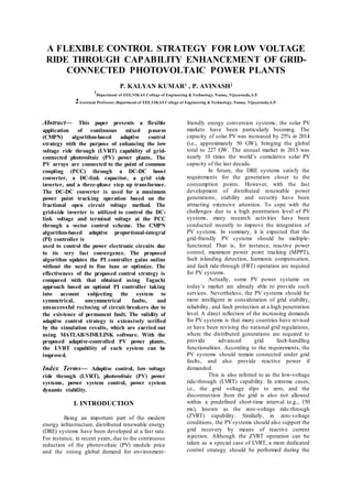
II. SYSTEM MODELING
In the low-voltage DRE system, the
single-phase configuration is a more competitive
solution. A generic control structure of the single-
phase grid-connected PVsystemis shown in Figure
1, with an option of a DC-DC converter, which is
used to boost up the PVpanel voltage to a suitable
level of the following-stage DC-AC converter. The
choice of single- or two-stage (i.e., without or with
the DC-DC converter) is dependent on the control
strategy, efficiency, cost, size and weight, etc. To
guarantee a high-quality sinusoidal grid current, the
inductor–capacitor–inductor (LCL) filter is adopted
to improve the switching harmonic with lighter and
smaller inductors.
Fig:1. Generic control structure of the single-phase
grid-connected photovoltaic (PV) system.
Maximum power point tracking (MPPT).
In normal conditions, the PV system
draws the maximum power from tshe PV arrays
(i.e., in MPPT operation) and transfers it to the grid
at unity power factor by using control strategy. The
widely employed control strategy in single-phase
inverters has two cascaded control loops. The inner
loop is a current loop, in which the grid current
quality can be guaranteed and the over current
protection is also ensured. The outer loop is a
voltage or power control loop, in which the voltage
of the DC-side can be ensured and a reference of
the inner current loop is calculated simultaneously
in the outer loop.
The PV arrays are connected to bus 18 of
the test system through a DC-DC boost converter, a
DC-link capacitor of 15 mF, a grid-side inverter,
three-phase step up transformers, and double circuit
transmission lines, as shown in Fig. 2.
This system is considered a compact
version of the original New England System and it
is used for realistic responses study. The IEEE 39-
bus system includes 39 buses out of which 19 are
load buses. There are 10 generators in the system.
Bus 31 at which generator 2 are connected is
defined as the slack bus. The total load and
generation of the system is 6098.1 and 6140.81
MW, respectively. The load model is considered to
be constant current and constant admittance load.
In order to test the PV power plant with the IEEE
39-bus system, the PV power plant is connected to
bus 18.
3. Fig.2. Grid-connected PV power plant Connection
of PV power plant.
A DC-DC boost converter is used to
control the output voltage of the PV plant in order
to satisfy the maximum output power condition.
This is done by controlling the duty cycle of
insulated gate bipolar transistor (IGBT) switch of
the converter, as indicated in Fig. 3. The fractional
open circuit voltage method is applied to fulfill the
maximum power condition.
Fig. 3. Control of the DC-DC converter.
A CMPN-based adaptive PI controller is
used for this purpose. The controller output signal
is compared with a triangular carrier waveform
signal of 4-kHz frequency to generate the firing
pulses of IGBT switch. A two-level, three-phase,
six IGBT switches inverter is proposed in this
study. The grid-side inverter is utilized to control
the DC-link voltage and terminal voltage at the
PCC through a vector control scheme, as illustrated
in Fig. 4.
The CMPN algorithm-based adaptive PI
controllers are developed for this purpose. A phase
locked loop (PLL) is dedicated to detect the
transformation angle from the three-phase voltages
at the PCC.
Fig. 4. Control block diagram of the grid-side
inverter.
One family of the adaptive filtering
algorithms is the mixed-norm adaptive filters that
have various forms. In the least mean mixed-norm
(LMMN) adaptive filter was presented, where it
combined the least mean square (LMS) and the
least mean fourth (LMF) algorithms. Moreover, a
robust mixed-norm (RMN) algorithm was proposed
and it combined the LMS algorithm with the least
absolute deviation (LAD) algorithm.
Then, a normalized RMN algorithm Once
the grid phase-to-ground fault is detected by the
grid synchronization, the photovoltaic (PV) system
should switch to the grid fault operational mode
with reactive power injection to support the grid
recovery. In different countries, to fulfill various
local conditions under national realities, the
suitable grid code has been proposed. Figure 5
exemplifies the voltage profiles for the possible
fault condition in some countries, where the PV
systems should operate under the specific condition
when the grid voltage is above the curves.
Fig: 5. Low-voltage (and zero-voltage) ride-
through requirements for grid-connected systems in
different countries.
Fig: 6. Reactive current injection requirements
under low-voltage ride-through/zero-voltage ride-
through (LVRT/ZVRT) operations.
4. III. SIMULATION RESULTS
The detailed model of a grid-connected
PV power plant is presented. The model involves a
complete switching model of the power electronic
circuits with the proposed adaptive control strategy
for obtaining realistic responses. The simulation
results are performed using the powerful power
system computer aided design
(MATLAB/SIMULINK) software.
In this scenario, a three-line to ground
(3LG) temporary fault takes place at time t=0.1 s
with duration of 0.1 s at fault point F. The CBs on
the faulted lines are opened at t=0.2s to clear fault.
Then, the CBs are reclosed again at t=1s.
Successful reclosure of the CBs means reclosure
under no fault condition.
Fig:7(a)
Fig: 7(b)
Fig:7(c)
Fig:7(d)
Fig:7(e)
Fig:7(f)
Fig. 7. Responses of proposed system for 3LG
temporary fault. (a) Vpcc. (b) Real power out of the
PCC. (c) Reactive power out of the PCC. (d) Vdc.
(e) Voltage at bus 18. (f) Inverter currents with the
proposed controller.
Fig:8(a)
5. Fig:8(b)
Fig:8(c)
Fig:8(d)
Fig:8(e)
Fig:8(f)
Fig. 8. Responses of conventional system for 3LG
temporary fault. (a) Vpcc. (b) Real power out of the
PCC. (c) Reactive power out of the PCC. (d) Vdc.
(e) Voltage at bus 18. (f) Inverter currents with the
proposed controller.
The Vpcc drops immediately from the
rated value (1 p.u) due to the effect of network
disturbance and the grid side inverter delivers a
good amount of reactive power that helps the Vpcc
to return back to the rated value, as indicated in
Fig. 7 & 8 (a). It is worth to note here that the Vpcc
response using the CMPN-adaptive PI control
strategy is better damped than that of using
Taguchi approach-based an optimal PI control
scheme, where it has lower maximum percentage
undershoot, lower maximum percentage overshoot,
lower settling time, and lower steady state error.
Fig. 7 & 8 (b) points out the real power out of the
PCC. It can be realized that the proposed controlled
DC-DC converter controls efficiently the maximum
output power of the PV plant at 1 p.u. The real
power out of the PCC reaches final 0.96 p.u due to
the converter, inverter, and transformer losses. The
reactive power out of the PCC, the Vdc , and
voltage at bus 18 are shown in Fig. 7 & 8 (c)–(e),
respectively. It can be noted that the responses
using the proposed adaptive control strategy are
very fast with minimum fluctuations. The online
CMPN adaptive algorithm distinguishes a high
speed convergence that updates the controller gains
in an expedite way. Fig. 7 & 8 (f) indicates the
direct axis and quadrature axis components of the
inverter output currents ( Id and Iq ). It can be
realized that the proposed controller limits the rms
inverter currents during the network disturbance to
a value of 1.2 p.u, which lies in an acceptable
range.
6. Fig:9(a)
Fig:9(b)
Fig:9(c)
Fig. 9. Vpcc response for unsymmetrical faults of
proposed system. (a) 2LG fault. (b) LL fault. (c)
1LG fault.
Fig:10(a)
Fig:10(b)
Fig:10(c)
Fig. 10. Vpcc response for unsymmetrical faults of
conventional system. (a) 2LG fault. (b) LL fault.
(c) 1LG fault.
Moreover, the proposed adaptive control
strategy is extensively verified by subject the
system to different types of unsymmetrical faults
such as double-line to ground (2LG), line-to-line
(LL), and single-line to ground (1LG) faults. Fig. 8
& 10(a)–(c) shows the Vpcc response under these
types of faults. All the transient responses using the
proposed control strategy are superior to that
obtained using Taguchi approach-based an optimal
PI control scheme. Therefore, the LVRT capability
of the grid connected PV power plants can be
further enhanced using the CMPN algorithm-based
adaptive PI control strategy.
B. Unsuccessful Reclosure of CBs
This scenario proposes a 3LG permanent
fault occurring at point F in Fig. (a). The fault
happens at t=0.1s and its duration is assumed to be
6.9 s. The CBs on the faulted lines are opened at
t=0.2s and reclosed again at t=1s. Unfortunately,
the CBs are closed on a permanent fault condition
at this instant and this means unsuccessful
reclosure of CBs. Therefore, the CBs are opened
again at t=1.1s and closed at t=7.1s, which means
after the fault duration.
7. Fig:11(a)
Fig:11(b)
Fig:11(c)
Fig:11(d)
Fig. 11. Responses for 3LG permanent fault of
conventional system. (a) Vpcc. (b) Real power out
of the PCC. (c) Reactive power out of the PCC. (d)
Vdc.
Fig:12(a)
Fig:12(b)
Fig:12(c)
Fig:12(d)
Fig. 12. Responses for 3LG permanent fault of
conventional system. (a) Vpcc. (b) Real power out
of the PCC. (c) Reactive power out of the PCC. (d)
Vdc.
8. Fig. 11 & 12(a)–(d) indicates the responses of
Vpcc, real and reactive powers out of the PCC, and
Vdc, respectively. All responses have faster and
better damped using the CMPN-based adaptive PI
control strategy. Moreover, through permanent
fault period, the Vpcc response lies in an
acceptable range that agrees with the PV power
plant grid codes. In addition, after permanent fault
clearance and CBs final closure, the returns back
with a fast response to its rated value. All system
responses can return to their pre-fault values.
Therefore, the proposed control strategy results in
an enhancement of the LVRT capability of grid-
connected PV power plants whatever under grid
temporary or permanent fault condition. The high
performance, accuracy, and superiority of the
proposed CMPN algorithm-based adaptive PI
controller to Taguchi-based an optimal PI
controller are due to its proper design, its high
convergence speed, and its flexibility to update the
controller gains automatically online to minimize
the error signals obtaining better results.
IV. CONCLUSION
This project has introduced a flexible
application of the CMPN algorithm-based adaptive
PI control strategy for enhancing the LVRT
capability of grid-connected PV power plants. The
proposed control strategy was applied to the DC-
DC boost converter for a maximum power point
tracking operation and also to the grid-side inverter
for controlling the Vpcc and Vdc. The CMPN
adaptive filtering algorithm was used to update the
proportional and integral gains of the PI controller
online without the need to fine tune or optimize.
For realistic responses, the PV power plant was
connected to the IEEE 39-bus New England test
system. The simulation results have proven that the
systemresponses using the CMPN algorithm-based
adaptive control strategy are faster, better damped,
and superior to that obtained using Taguchi
approach-based an optimal PI control scheme
during the following cases:
1) subject the system to a symmetrical 3LG
temporary fault;
2) subject the system to different unsymmetrical
faults;
3) subject the system to a symmetrical 3LG
permanent fault and unsuccessful reclosure of CBs.
It can be claimed from the simulation
results that the LVRT capability of grid-connected
PV power plants can be further enhanced using the
proposed adaptive control strategy whatever under
grid temporary or permanent fault condition. By
this way, the PV power plants can contribute to the
grid stability and reliability, which represents a
greater challenge to the network operators.
Moreover, the proposed algorithm can be also
applied to other renewable energy systems for the
same purpose.
V. REFERENCES
[1] PV Power Plants 2014 Industry Guide [Online].
Available: http://www.pvresources.com
[2] D. L. Brooks and M. Patel, “Panel: Standards &
interconnection requirements for wind and solar
generation NERC integrating variable generation
task force,” in Proc. IEEE Power Eng. Soc.
General Meeting 2011, Jul. 2011, pp. 1–3.
[3] G. J. Kish, “Addressing future grid
requirements for distributed energy resources,”
M.Sc. thesis, Dept. Elect. Comput. Eng., Univ.
Toronto, Toronto, ON, Canada, 2011.
[4] Y. Yang, F. Blaabjerg, and Z. Zou,
“Benchmarking of grid fault modes in single-phase
grid-connected photovoltaic systems,” IEEE Trans.
Ind. Applicat., vol. 49, no. 5, pp. 2167–2176,
Sep./Oct. 2013.
[5] Y. Yang, F. Blaabjerg, and H. Wang, “Low-
voltage ride-through of single-phase
transformerless photovoltaic inverters,” IEEE
Trans. Ind. Applicat., vol. 50, no. 3, pp. 1942–
1952, May/Jun. 2014.
[6] K. Kawabe and K. Tanaka, “Impact of dynamic
behavior of photovoltaic power generation systems
on short-term voltage stability,” IEEE Trans.
Power Syst., vol. 30, no. 6, pp. 3416–3424, Nov.
2015.
[7] M. S. El Moursi, W. Xiao, and J. L. Kirtley,
“Fault ride through capability for grid interfacing
large scale PV power plants,” IET Gener., Transm.,
Distrib., vol. 7, no. 5, pp. 1027–1036, 2013.
[8] Y. Wu, C.-H. Chang, Y. Chen, C. Liu, and Y.
Chang, “A current control strategy for three-phase
PV power system with low-voltage ridethrough,” in
Proc. IET Int. Conf. Advances on Power System
Control, Operation, Management (APSCOM),
2012, pp. 1–6.
[9] M. K. Hossain and M. H. Ali, “Low voltage
ride through capability enhancement of grid
connected PV system by SDBR,” in Proc. IEEE
PES T&D Conf. Expo., 2014, pp. 1–5.
P. KALYAN KUMAR1. He received
B.Tech Degree in Electrical and Electronics
Engineering from Chirala Engineering College,
Chirala, Andhra Pradesh and Pursing M.Tech in
Power Electronics and Electrical Drives form
Viakas College Of Engineering & Technology,
Nunna, Vijayawada, Andhra Pradesh, India.
9. Mr .P Avinash2, Born on 17th Aug
1988, Hyderabad, Andhra Pradesh, India. He
received the B.Tech. Degree in Electrical and
Electronics Engineering from JNTU Kakinada,
Andhra Pradesh, and M.S. Degree in Electrical and
Electronic Engineering from the Staffordshire
University, Stafford, United kingdom, And aslo he
received M.Tech. Degree in Electrical Power
systems from JNTU Kakinada. Presently working
as Assistant Professor in the Electrical and
Electronic Engineering Department in Vikas
college of Engineering & Technology , Nunna,
Vijayawada, Andhra Pradesh, India. He has 5 years
of teaching experience. His main research area is
power systems.
.