
Recommended
More Related Content
What's hot
What's hot (17)
Similar to Unit 2 Complete Notes.pdf
Similar to Unit 2 Complete Notes.pdf (20)
Recently uploaded
Recently uploaded (20)
Unit 2 Complete Notes.pdf
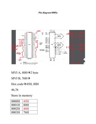
- 1. Pin diagram 8085a MVI A, 80H2 byte MVI B, 76H Hex code45H, 80H 46,76 Store in memory 0000H 45H 0001H 80H 0002H 46H 0003H 76H
- 2. 0004H Addressing modes of 8085
- 3. Various ways of specifying the operands in the instruction are called addressing modes. 8085 supports five different types of Addressing mode. MVI A, 80H 1.Register Addressing mode: instructions in which operand is moving from register to register are called register addressing mode. Ex: MOV A, B BA data move from B to A Ex: ADD C, ADD B, ADD H A+CA If we want to add B & C MOV A, B ADD C 2.Immediate Addressing mode: when operand is given in the instruction directly, then the instruction is a example of Immediate Addressing mode. MVI A, 75H=2 byte
- 4. MVI C, 45H MVI H, 7AH rp register pair (B, D, H). LXI rp, 16 bit data Ex: LXI B, 45ACH=3 byte B=45H, C=ACH 3.Direct Addressing mode: When the address of the operand is given in the instruction directly then in that instruction Direct Addressing mode is used. 0014H 45H 054CH 96H 2200H 6BH LDA 0014H MOV B, A A=45H 4.Indirect Addressing mode: When the address of the operand is given in the instruction indirectly then in that instruction indirect Addressing mode is used. Assume reg B=05H & reg C=4CH MVI r, 8bit data MOV rd, rs LDAX rp LDAX B Register pair BC=054CHdata96H
- 5. A=96H 5.Implied Addressing mode: In instructions where operand is available in the opcode, then those instructions are the example of Implied Addressing mode. Ex. CMAcomplement accumulator A=7CH0111 1100 1000 0011 Data Transfer operations (MOV, MVI, OUT, IN) 1.Byte=? (1, 2, 3) 2.Machine cycle used in an instruction=? (1, 2, 3, 4, 5)no. of operations performed by microprocessor 3.T-states used in an instruction=? (4, 7, 10, 13, 16) In some special cases T states will be (6, 18) Userwrite in assemblyconvert into hex codestore in memory Microprocessor taskfetchdecodeexecute Operation T-states used OF 4, 6(in some special case) MR 3 MW 3 IOR 3 IOW 3
- 6. OF, MR, MR, MWTstates13 r= A, B, C, D, E, H, L, M Data Transfer operations (MOV, MVI, IN, OUT) 1.MOV rd, rs ASSUME (B=45H, C=A1H) Ex: MOV B, C (CB) B= A1H, C=A1H BYTE: 1 M/C: 1 (OF) T: 4 HA MOV A, H (register addressing mode is used) 2.MVI r, 8-bit data B=45H MVI B, 45H BYTE: 2
- 7. M/C: 2(OF, MR) T: 7 3.IN 8-bit address EX: IN 80H BYTE: 2 M/C: 3 (OF, MR, IOR) T: 10 4.OUT 8-bit address OUT 7CH BYTE: 2 M/C: 3 (OF, MR, IOW) T: 10
- 8. Machine control operation: 1.HLT:1 byte, M/c=1, T=5 2.NOP: no operation: 1 byte, M/c=1, T=4 0001 45 0002 46 0003 NOP 0004 45 0005 12 0006 45 Arithmetic operations: ADD, ADI, SUB, SUI, INR, DCR 1.ADD r: if we want to add the data of A & B ADD B (A+BA) if we want to add the data of A & H ADD H (A+HA) Byte: 1 M/C:1 T:4 Flags affected: S, Z, AC, P, CY
- 9. EX: assume we have two data 4C & 2D, add these data & store the result in reg H. Program: MVI A, 2DH MVI B, 4CH ADD B MOV H, A HLT Ex2: Read from (1st input device) 80H & (2nd input device) 81H, then add both the data & display the result into output device (45H). Program: IN 80H MOV B, A IN 81H ADD B OUT 45H HLT 2.ADI 8-bit data Ex: ADI 76H (A+ 76HA) Byte: 2 M/C: 2 T: 7 Flags affected: S, Z, AC, P, CY
- 10. 3.SUB r: (A-rA) EX: A-C SUB C Byte: 1 M/C: 1 T: 4 Flags affected: S, Z, AC, P, CY 4.SUI 8 bit data ASSUME A=4A SUI 12H 4A-12A Byte: 2 M/C: 2 T: 7 Flags affected: S, Z, AC, P, CY 5.INR r EX: H=4DH
- 11. INR H H=4EH Byte: 1 M/C: 1 T: 4 Flags affected: S, Z, AC, P CY will not affected by INR A=FFH INR A FF+1 6.DCR r B=8AH DCR B B=89H Byte: 1 M/C: 1
- 12. T: 4 Flags affected: S, Z, AC, P CY will not affected by DCR Logical instructions Logic Operations (ANA, ANI, ORA, ORI, XRA, XRI) 1. ANA r ANA B (logical AND operation between A, result goes to A) Ex: A=48H, B=A6H ANA B A=00H B=A6H Flags:
- 13. Byte: 1 M/C: 1 T: 4 ANI 8-bit data ANI 7FH Byte: 2 M/C: 2 T: 7 ORA r
- 14. Byte: 1 M/C: 1 T: 4 ORI 8 bit data Byte: 2 M/C: 2 T: 7 XRA r Byte: 1 M/C: 1 T: 4
- 15. XRI 8 bit data Byte: 2 M/C: 2 T: 7 Programs MOV, MVI, IN, OUT ADD, ADI, SUB, SUI, INR, DCR ANA, ANI, ORA, ORI, XRA, XRI PROG1: B=7CH, D=56H add these data & store the result in reg H. MOV A, B ADD D MOV H, A HLT PROG2: READ DATA FROM INPUT DEVICE 80H & 81H, LOGICAL OR BOTH THE DATA & DISPLAY THE RESULT AT OUTPUT 83H. PORG3: SWAP THE DATA OF REG H & L. Branch operation (JMP, CALL, RESTART)
- 16. Prog: wap to logically XOR the input data 4DH & 2CH. Show the result in output of address 83H. Also show the status of flags. Prog: wap to subtract to 8 bit numbers stored in B=ACH & C=69H. Store the result in reg E. Also show the status of flags. ACH1010 1100 69H 0110 1001 CALL instruction: CALL 16 bit address JMP 2000H (PC=2000H) CALL 2000H(PC=2000H) We jump to subroutine with a CALL instruction. Subroutine: is a group of instructions written separately from the main program.