SlideShare a Scribd company logo
1 of 20
Download to read offline
Illumination calculation
Formula:
Required illumination=
𝐀𝐫𝐞𝐚×𝐒𝐭𝐚𝐧𝐝𝐚𝐫𝐝 𝐢𝐥𝐥𝐮𝐦𝐢𝐧𝐚𝐭𝐢𝐨𝐧
𝐃𝐞𝐩𝐫𝐢𝐜𝐢𝐚𝐭𝐢𝐨𝐧 𝐟𝐚𝐜𝐭𝐨𝐫×𝐔𝐭𝐢𝐥𝐢𝐳𝐚𝐭𝐢𝐨𝐧 𝐟𝐚𝐜𝐭𝐨𝐫
Entry:
Area=293.624 sq.
Standard illumination= 3.5 ft.-candle
Total lumen required=4500 lumen
Lobby:
Area=581 sq. ft.
Standard illumination=4 ft. candle
Total lumen required=5810 lumen
Office 1:
Area= 173.94 sq. ft.
Standard illumination= 10 ft. candle
Total lumen required= 3106 lumen
Office2:
Area= 256.025 sq. ft.
Standard illumination= 10 ft. candle
Total lumen required= 4575 lumen
Multipurpose hall:
Area= 2544.22 sq. ft.
Standard illumination= 10 ft. candle
Total lumen required= 53212.9 lumen
Pavement:
Area= 2614.1 sq. ft.
Standard illumination= 2.5 ft. candle
Total lumen required= 10211.32 lumen
Dinning Space:
Area= 546.42 sq. ft.
Standard illumination= 10 ft. candle
Total lumen required= 11358.75 lumen
Dinning space basin cabinet:
Area= 28.2 sq. ft.
Standard illumination= 5 ft. candle
Total lumen required= 358.75 lumen
Open space:
Area= 150 sq. ft.
Standard illumination= 5 ft. candle
Total lumen required= 1562.5 lumen
Corridor:
Area= 348.42 sq. ft.
Standard illumination= 5 ft. candle
Total lumen required= 3629.4 lumen
Pantry:
Area= 95.63 sq. ft.
Standard illumination= 5 ft. candle
Total lumen required= 853.84 lumen
Single Bed 1:
Area= 98.4 sq. ft.
Standard illumination= 10 ft. candle
Total lumen required= 1537.5 lumen
Single Bed 2:
Area= 122.52 sq. ft.
Standard illumination= 10 ft. candle
Total lumen required= 1537.5 lumen
Kitchen:
Area= 217.82 sq. ft.
Standard illumination= 20 ft. candle
Total lumen required= 9075 lumen
Pass way:
Area= 174.695 sq. ft.
Standard illumination= 5 ft. candle
Total lumen required= 1819.74 lumen
Dressing room (Gents):
Area= 64.02 sq. ft.
Standard illumination= 5 ft. candle
Total lumen required= 666.875 lumen
Toilet-1(Gents):
Area= 22.64 sq. ft.
Standard illumination= 5 ft. candle
Total lumen required= 283 lumen
Toilet-2(Gents):
Area= 22.64 sq. ft.
Standard illumination= 5 ft. candle
Total lumen required= 283 lumen
Dressing room (Ladies):
Area= 64.02 sq. ft.
Standard illumination= 5 ft. candle
Total lumen required= 666.875 lumen
Toilet-1(Ladies):
Area= 21.32 sq. ft.
Standard illumination= 5 ft. candle
Total lumen required= 266.5 lumen
Toilet-2(Ladies):
Area= 21.32 sq. ft.
Standard illumination= 5 ft. candle
Total lumen required= 266.5 lumen
Toilet:
Area= 32.5 sq. ft.
Standard illumination= 5 ft. candle
Total lumen required= 406.25 lumen
Store room:
Area= 72.45 sq. ft.
Standard illumination= 5 ft. candle
Total lumen required= 754.68 lumen
Circuit current & power calculation
Distribution board 1
Circuit: (SB-1)
Sl. No Specification Number of points Wattage per unit Wattage
1 Down light 3 25 75
2. Lobby Down light 4 25 100
3 Corridor Down
light
1 20 20
4. 2 pin socket 1 100 100
Total 295
Max current=1.23 A
Circuit: (SB-5)
Max current: 3.75A
Circuit: (SB-6)
Max current: 4.02A
Circuit: (SB-7)
Sl. no Specification Number of points Wattage per unit Wattage
1. Tube light 6 40 240
2. fan 6 60 360
3. 2 pin socket 1 100 100
Total 700
Max current: 2.9A
Sl. no Specification Number of points Wattage per unit Wattage
1. Tube light 6 40 240
2. Fan 6 60 360
3. 3 pin 2 100 200
4. 2 pin 1 100 100
5. Wall bracket 1 65 65
Total 960
Sl no Specification Number of points Wattage per unit Wattage
1. Tube light 6 40 240
2. Fan 6 60 360
3. 3 pin socket 1 100 100
4. 2 pin socket 1 100 100
Total 800
Circuit: (SB-2):
Sl. no Specification Number of points Wattage per unit Wattage
1. Tube light 1 40 40
2. Fan 1 60 60
3. 2pin socket 1 100 100
4. 3pin socket 1 100 100
Total 300
Max current=1.25A
Circuit: (SB-3):
Sl. no Specification Number of points Wattage per unit Wattage
1 Tube light 1 40 40
2 Wall bracket 1 25 25
3. Fan 2 60 120
4. 3pin socket 2 100 200
5. 2pin socket 1 100 100
Total 485
Max current= 2.02A
Circuit: (SB-4):
Sl. no Specification Number of points Wattage per unit Wattage
1 Down light 1 25 25
2 2pin socket 1 100 100
Total 125
Max current=0.5A
Circuit: (SB-8)
Sl. no Specification Number of points Wattage per unit Wattage
1 Wall bracket 1 25 25
Total 25
Max current=0.11A
Circuit: (SB-9)
Sl. no Specification Number of points Wattage per unit Wattage
1 Wall bracket 1 25 25
2 Down light 1 15 15
3 Fan 1 60 60
4 3 pin socket 1 100 100
5 2 pin socket 1 100 100
Total 300
Max Current = 1.25A
Circuit: (SB-10)
Sl. no Specification Number of points Wattage per unit Wattage
1 Air conditioner 1 6000 6000
Total 6000
Max current=25A
Total current=41.34A
Distribution Board 2
Circuit: (SB-11)
Sl. no Specification Number of
points
Wattage per
unit
Wattage Sl. no
1 Tube light 1 40 40 0.16
2 Down light 2 65 130
3 Fan 4 60 240
4 3 pin socket 2 100 200
5 2 pin socket 1 100 100
Total 710
Max Current= 2.9A
Circuit: (SB-12)
Sl. no Specification Number of points Wattage per unit Wattage
1 Down light 1 9 9
2 Wall bracket 1 65 65
Total 74
Max Current = 0.31A
Circuit: (SB-13)
Sl. no Specification Number of points Wattage per unit Wattage
1 Down light 1 9 9
2 Wall Bracket 2 5 10
3 2 pin socket 1 100 100
Total 119
Max current = 0.5A
Circuit: (SB-14)
Sl. no Specification Number of points Wattage per unit Wattage
1 Down light 1 9 9
2 Wall Bracket 2 5 10
3 2 pin socket 1 100 100
Total 119
Max current = 0.5A
Circuit: (SB-15)
Sl. no Specification Number of points Wattage per unit Wattage
1 Wall bracket 2 65 130
2 Fan 1 60 60
3 Exhaust Fan 1 100 100
4 3pin socket 2 100 200
5 2 pin socket 1 100 100
Total 590
Max Current: 2.45A
Circuit: (SB-16)
Sl. no Specification Number of points Wattage per unit Wattage
1 Wall Bracket 1 15 15
2 Fan 1 60 60
3 3 pin socket 1 100 100
4 2 pin socket 1 100 100
Total 275
Max Current: 1.2A
Circuit: (SB-17)
Sl. no Specification Number of points Wattage per unit Wattage
1 Wall Bracket 1 15 15
2 Fan 1 60 60
3 3 pin socket 1 100 100
4 2pin socket 1 100 100
Total 275
Max Current: 1.15A
Circuit: (SB-18)
Sl. no Specification Number of points Wattage per unit Wattage
1 Wall Bracket 1 20 20
2 Fan 1 60 60
3 2 pin socket 1 100 100
Total 180
Max Current: 0.75A
Circuit: (SB-19)
Sl. no Specification Number of points Wattage per unit Wattage
1 Wall Bracket 1 5 5
2 Wall Bracket 1 20 20
3 Fan 1 60 60
4 2 pin socket 1 100 100
5 3 pin socket 1 100 100
Total 285
Max Current: 1.18A
Circuit: (SB-20)
Sl. no Specification Number of points Wattage per unit Wattage
1 Wall bracket 1 30 30
2 Fan 1 60 60
3 3 pin socket 1 100 100
4 2 pin socket 1 100 100
Total 290
Max Current = 1.2A
Circuit: (SB-21)
Sl. no Specification Number of points Wattage per unit Wattage
1 Wall bracket 1 25 25
2 Fan 1 60 60
3 3 pin socket 1 100 100
4 2 pin socket 1 100 100
Total 285
Max Current = 1.2A
Total current=13.07A
Summary table for power circuit
Sl. no description Amperage Total
Power circuit
1
Power circuit 2 (main
board to sub main 1)
41.34
54.41
Power circuit 3 (main
board to sub main 2)
13.07
Power circuit
2
Power circuit 4 1.23
41.34
Power circuit 5 1.25
Power circuit 6 2.02
Power circuit 7 .5
Power circuit 8 3.75
Power circuit 9 4.02
Power circuit 10 2.9
Power circuit 11 0.11
Power circuit 12 1.25
Power circuit 13 25
Power circuit
3
Power circuit 14 2.9
13.07
Power circuit 15 0.31
Power circuit 16 0.5
Power circuit 17 0.5
Power circuit 18 0.45
Power circuit 19 1.2
Power circuit 20 1.15
Power circuit 21 0.75
Power circuit 22 1.18
Power circuit 23 1.2
Power circuit 24 1.2
Conduit Calculation
From Conduit Layout we can see that, there are 21 (Twenty One) circuits in total.
Specification as follows:
 The Height of the Light Bracket from the Floor Level = 8 Feet.
 The Height of the Switch from the Floor Level = 5 Feet.
 The Height of the 3-pin Switch Board from the Floor Level = 2 Feet.
 The Height of the Ceiling Fan from the Floor Level = 10 Feet.
Main Board:
1. Main Board to Sub Main 1 = 4 ft.
2. Main Board to Sub Main 2 = 38.167 ft.
Sub Main Board:
1. Sub Main 1 to SB-1= 35 ft.
2. Sub Main 1 to SB-2= 35.5 ft.
3. Sub Main 1 to SB-3= 25 ft.
4. Sub Main 1 to SB-4= 24.5 ft.
5. Sub Main 1 to SB-5= 41.58 ft.
6. Sub Main 1 to SB-6= 53.58 ft.
7. Sub Main 1 to SB-7= 65.58 ft.
8. Sub Main 1 to SB-8= 13 ft.
9. Sub Main 1 to SB-9= 13.08 ft.
10. Sub Main 1 to SB-10= 86.58 ft.
11. Sub Main 2 to SB-11=36ft
12. SB-11 to SB-12= 23 ft.
13. Sub Main 2 to SB-13= 22 ft.
14. Sub Main 2 to SB-14= 22 ft.
15. Sub Main 2 to SB-15= 27.58 ft.
16. Sub Main 2 to SB-16= 24 ft.
17. Sub Main 2 to SB-17= 13.33 ft.
18. Sub Main 2 to SB-18= 25 ft.
19. Sub Main 2 to SB-19= 29 ft.
20. Sub Main 2 to SB-20= 30 ft.
21. Sub Main 2 to SB-21= 27 ft.
Table for SB wise conduit
Sl. no Description Distance in ft.
1. SB-1 103.25
2. SB-2 33.167
3. SB-3 45.08
4. SB-4 8.416
5. SB-5 132
6. SB-6 120
7. SB-7 119
8. SB-8 5
9. SB-9 29.33
10. SB-10 5
11. SB-11 97.58
12. SB-12 20.84
13. SB-13 22
14. SB-14 22
15. SB-15 27.58
16. SB-16 24
17. SB-17 13.33
18. SB-18 25
19. SB-19 29
20. SB-20 30
21. SB-21 27
total 938.573
Summary Table for Conduit calculation
Serial no. Description Distance in Feet Total
1 Main Board to Sub Main 1 4
42.167
Main Board to Sub Main 2 38.167
2
Sub main 1
to
SB-1
293.4
449.31
SB-2
SB-3
SB-4
SB-5
SB-6
SB-7
SB-8
SB-9
SB-10
SB-11
Sub main 2
to
SB-12
155.91
SB-13
SB-14
SB-15
SB-16
SB-17
SB-18
SB-19
SB-20
SB-21
3 Switch board 938.573 938.573
total 1430.05
The Length of Total Conduit = 1430.05 ft.
Considering 10% wastage,
The Length of Total Conduit = 1573.055 ft.
Wire calculation
Sl. no
Board
specification
Distance in
feet
Cost per unit Cost
1 SB-1 1/1.40 mm 182 6.1874 1126.107
2 SB-2 1/1.40 mm 51.5 6.1874 318.6511
3 SB-3 1/1.40 mm 146.84 6.1874 908.5578
4 SB-4 1/1.40 mm 8.42 6.1874 52.09791
5 SB-5 1/1.40 mm 383.5 6.1874 2372.868
6 SB-6 1/1.40 mm 352 6.1874 2177.965
7 SB-7 1/1.40 mm 309 6.1874 1911.907
8 SB-8 1/1.40 mm 5 6.1874 30.937
9 SB-9 1/1.40 mm 29.33 6.1874 181.4764
10 SB-10 1/3.55mm 86.58 23.37 2023.375
11 SB-11 1/1.40 mm 211.16 6.1874 1306.531
12 SB-12 1/1.40 mm 23.84 6.1874 147.5076
13 SB-13 1/1.40 mm 16.84 6.1874 104.1958
14 SB-14 1/1.40 mm 16.84 6.1874 104.1958
15 SB-15 1/1.40 mm 83.94 6.1874 519.3704
16 SB-16 1/1.40 mm 18 6.1874 111.3732
17 SB-17 1/1.40 mm 33 6.1874 204.1842
18 SB-18 1/1.40 mm 13.94 6.1874 86.25236
19 SB-19 1/1.40 mm 34.416 6.1874 212.9456
20 SB-20 1/1.40 mm 38 6.1874 235.1212
21 SB-21 1/1.40 mm 20.84 6.1874 128.9454
22.
Main board
to sub main
1
7/1.70 mm 8 52.169 417.352
23
Main board
to sub main
2
1/1.80 mm 76.32 9.43 359.8488
Total 2149.306 15041.76
Total neutral wire required=1235.16 ft.
Cost of neutral wire (1/1.40mm)=1235.16×6.1874=7642.42TK
Summary table for wire cost
Specification Required length Required length
with 10% wastage
Cost per unit cost
1/1.40 mm 3213.566 3534.9226 6.1874 21871.98
1/3.55 mm 86.58 95.238 23.37 2225.712
7/1.70 mm 8 8.8 52.169 459.087
1/1.80 mm 76.32 83.96 9.43 791.7428
Total 2534.52186
Cost calculation
Wire and conduit cost
Item Specification Total unit(ft.) Cost (per ft.) Cost (TK)
Wire
(PVC insulated
and PVC
sheathed)
1/1.40 mm 3534.9226 6.1874 21871.98
1/3.55 mm 95.238 23.37 2225.7
7/1.70 mm 8.8 52.169 459.0872
1/1.80 mm 83.96 9.43 791.7428
Conduit 1573.055 10.49 16501.346
Total 41849.86
Accessories cost
Sl. no Material used Quantity Rate(Tk/piece) Cost
1. Tee 30 6 180
2. Elbow 46 3 138
3. Circular box 15 6 90
4. Junction box 10 6 60
5. Surface
mounting plastic
box
21 145 3045
6. Lamp holder 32 55 1760
7. Tube stand 21 150 3150
8. Switch board 21 198 4158
9. Switch 102 35 3570
10. Fuse 21 35 735
11. 2 pin Socket(6A) 21 35 735
12. 3 pin
socket(6/16A)
16 175 2800
13. Screw 388 0.5 194
14. Distribution
board
2 800 1600
15. Fan regulator(%
steps)
33 580 19140
16. Mini circuit
breaker
11 260 2860
17. Ceiling rose 57 35 1995
18. Fire alarm 1 1200 1200
19. Indicator lamp 21 80 1680
20. Rubber Tape 12 18 216
21. Royal plug 388 .25 97
Total 46703
Labor cost
Total no. of load and plug point=102
Labor cost=110 TK/load and plug point
So, total labor cost=110×102= 11220 TK.
Summary of cost calculation
Cost specification Cost(TK)
Wire and conduit cost 41849.86
Accessories cost 46703
Labor cost 11220
Total Cost 99772.86
The total cost for “KUET GUEST HOUSE – Ground floor” wiring is 99,775TK.
SB
SB
LOADDESIGNOFKUETGUESTHOUSECUM
CLUBBUILDING-GROUNNDFLOOR
FLUROSCENT
TUBE
EXHAUSTFAN
SURFACE
MOUNTINGLIGHT
MAINDISTRIBUTION
BOARD
SUBDISTRIBUTION
BOARD
AIRCONDITIONER
UNIT
3PIN
SOCKET
SWITCH
BOARD
CEILING
FAN
WALL
BRACKET
E
F
MDB
SDB
A
C
P
SB
PAVEMENT
P
SB
A
C
P
SBPSB
E
F
P
P
P
SB
SB
P
SDB
SB
SB
SB
SB
SB
SB
MDB
13'
P
P
SB
P
P
P
P
P
P
SDB
SBSB
SB
SB
SB
SBP
Wiring design of kuet guest house cum club building ground floor

More Related Content

What's hot

cable ampacity calculations- IEC
cable ampacity calculations- IECcable ampacity calculations- IEC
cable ampacity calculations- IECJoe Khan
 
Design of transformer
Design of transformerDesign of transformer
Design of transformerSubrata Dey
 
Cable sizing to withstand short-circuit current - Example
Cable sizing to withstand short-circuit current - ExampleCable sizing to withstand short-circuit current - Example
Cable sizing to withstand short-circuit current - ExampleLeonardo ENERGY
 
Principles of Cable Sizing
Principles of Cable SizingPrinciples of Cable Sizing
Principles of Cable SizingLeonardo ENERGY
 
#Solar mooc voltage drop calculations
#Solar mooc voltage drop calculations#Solar mooc voltage drop calculations
#Solar mooc voltage drop calculationssolpowerpeople
 
Heatsink derating-calculation
Heatsink derating-calculationHeatsink derating-calculation
Heatsink derating-calculationAurlieReynaud2
 
Design of transformer and chock coil
Design of transformer and chock coilDesign of transformer and chock coil
Design of transformer and chock coilShubham Champaneri
 
#Solar mooc 2009 nabcep study guide solutions 1-29
#Solar mooc 2009 nabcep study guide solutions 1-29#Solar mooc 2009 nabcep study guide solutions 1-29
#Solar mooc 2009 nabcep study guide solutions 1-29solpowerpeople
 
Changes to 2014 NEC Interconnection Rule 705.12
Changes to 2014 NEC Interconnection Rule 705.12Changes to 2014 NEC Interconnection Rule 705.12
Changes to 2014 NEC Interconnection Rule 705.12solpowerpeople
 
#SolarMOOC Random Problems from 2009 NABCEP STUDY GUIDE
#SolarMOOC Random Problems from 2009 NABCEP STUDY GUIDE#SolarMOOC Random Problems from 2009 NABCEP STUDY GUIDE
#SolarMOOC Random Problems from 2009 NABCEP STUDY GUIDEsolpowerpeople
 
Power cable selection, cable selection Methodology
Power cable selection, cable selection Methodology Power cable selection, cable selection Methodology
Power cable selection, cable selection Methodology wessam alaslmi
 
WIDE BAND TRANSFORMER
WIDE BAND TRANSFORMERWIDE BAND TRANSFORMER
WIDE BAND TRANSFORMERKUMAR GOSWAMI
 
LE Calculations 2
LE Calculations 2LE Calculations 2
LE Calculations 2grantlerc
 
Problemas transferencia de_calor
Problemas transferencia de_calorProblemas transferencia de_calor
Problemas transferencia de_calorAlejandroOlivares41
 
Group 5-4ChEA
Group 5-4ChEAGroup 5-4ChEA
Group 5-4ChEA4ChEAB08
 

What's hot (20)

Transformer
TransformerTransformer
Transformer
 
cable ampacity calculations- IEC
cable ampacity calculations- IECcable ampacity calculations- IEC
cable ampacity calculations- IEC
 
Design of transformer
Design of transformerDesign of transformer
Design of transformer
 
Cable sizing to withstand short-circuit current - Example
Cable sizing to withstand short-circuit current - ExampleCable sizing to withstand short-circuit current - Example
Cable sizing to withstand short-circuit current - Example
 
Principles of Cable Sizing
Principles of Cable SizingPrinciples of Cable Sizing
Principles of Cable Sizing
 
Unsteady State Basics
Unsteady State BasicsUnsteady State Basics
Unsteady State Basics
 
#Solar mooc voltage drop calculations
#Solar mooc voltage drop calculations#Solar mooc voltage drop calculations
#Solar mooc voltage drop calculations
 
Heatsink derating-calculation
Heatsink derating-calculationHeatsink derating-calculation
Heatsink derating-calculation
 
Design of transformer and chock coil
Design of transformer and chock coilDesign of transformer and chock coil
Design of transformer and chock coil
 
#Solar mooc 2009 nabcep study guide solutions 1-29
#Solar mooc 2009 nabcep study guide solutions 1-29#Solar mooc 2009 nabcep study guide solutions 1-29
#Solar mooc 2009 nabcep study guide solutions 1-29
 
Changes to 2014 NEC Interconnection Rule 705.12
Changes to 2014 NEC Interconnection Rule 705.12Changes to 2014 NEC Interconnection Rule 705.12
Changes to 2014 NEC Interconnection Rule 705.12
 
Dem-solved-problems
Dem-solved-problemsDem-solved-problems
Dem-solved-problems
 
#SolarMOOC Random Problems from 2009 NABCEP STUDY GUIDE
#SolarMOOC Random Problems from 2009 NABCEP STUDY GUIDE#SolarMOOC Random Problems from 2009 NABCEP STUDY GUIDE
#SolarMOOC Random Problems from 2009 NABCEP STUDY GUIDE
 
Power cable selection, cable selection Methodology
Power cable selection, cable selection Methodology Power cable selection, cable selection Methodology
Power cable selection, cable selection Methodology
 
WIDE BAND TRANSFORMER
WIDE BAND TRANSFORMERWIDE BAND TRANSFORMER
WIDE BAND TRANSFORMER
 
LE Calculations 2
LE Calculations 2LE Calculations 2
LE Calculations 2
 
Problemas transferencia de_calor
Problemas transferencia de_calorProblemas transferencia de_calor
Problemas transferencia de_calor
 
Designing variable choke coil
Designing variable choke coilDesigning variable choke coil
Designing variable choke coil
 
4b Group1
4b Group14b Group1
4b Group1
 
Group 5-4ChEA
Group 5-4ChEAGroup 5-4ChEA
Group 5-4ChEA
 

Similar to Wiring design of kuet guest house cum club building ground floor

97fd01fe-d033-40ce-964b-f2b030a90d30-150210013729-conversion-gate01
97fd01fe-d033-40ce-964b-f2b030a90d30-150210013729-conversion-gate0197fd01fe-d033-40ce-964b-f2b030a90d30-150210013729-conversion-gate01
97fd01fe-d033-40ce-964b-f2b030a90d30-150210013729-conversion-gate01Vinoth Kanna
 
The art of_electronics
The art of_electronicsThe art of_electronics
The art of_electronicschenna_kesava
 
Edwards Signaling EGCF-HDVMH Installation Manual
Edwards Signaling EGCF-HDVMH Installation ManualEdwards Signaling EGCF-HDVMH Installation Manual
Edwards Signaling EGCF-HDVMH Installation ManualJMAC Supply
 
Electrical design and estimating cost.
Electrical design and estimating cost.Electrical design and estimating cost.
Electrical design and estimating cost.Turja Deb
 
Optimal Cable Sizing in PV Systems: Case Study
Optimal Cable Sizing in PV Systems: Case StudyOptimal Cable Sizing in PV Systems: Case Study
Optimal Cable Sizing in PV Systems: Case StudyLeonardo ENERGY
 
Edwards Signaling 2452THS-1575-W Installation Manual
Edwards Signaling 2452THS-1575-W Installation ManualEdwards Signaling 2452THS-1575-W Installation Manual
Edwards Signaling 2452THS-1575-W Installation ManualJMAC Supply
 
Tibre table of contents
Tibre table of contentsTibre table of contents
Tibre table of contentsxquitah
 
Cong tac o_cam_panasonic_2014
Cong tac o_cam_panasonic_2014Cong tac o_cam_panasonic_2014
Cong tac o_cam_panasonic_2014Lãng Quên
 
4N25 - Datasheet - AVAGO TECHNOLOGIES LIMITED
4N25 - Datasheet - AVAGO TECHNOLOGIES LIMITED4N25 - Datasheet - AVAGO TECHNOLOGIES LIMITED
4N25 - Datasheet - AVAGO TECHNOLOGIES LIMITEDMarioFarias18
 
Edwards Signaling EGCF-HDVM Installation Manual
Edwards Signaling EGCF-HDVM Installation ManualEdwards Signaling EGCF-HDVM Installation Manual
Edwards Signaling EGCF-HDVM Installation ManualJMAC Supply
 
Edwards Signaling EGC-HDVM Installation Manual
Edwards Signaling EGC-HDVM Installation ManualEdwards Signaling EGC-HDVM Installation Manual
Edwards Signaling EGC-HDVM Installation ManualJMAC Supply
 
2N2222のデータシート(英語版)
2N2222のデータシート(英語版)2N2222のデータシート(英語版)
2N2222のデータシート(英語版)Tsuyoshi Horigome
 

Similar to Wiring design of kuet guest house cum club building ground floor (20)

Apartment design
Apartment design Apartment design
Apartment design
 
Ece523 folded cascode design
Ece523 folded cascode designEce523 folded cascode design
Ece523 folded cascode design
 
97fd01fe-d033-40ce-964b-f2b030a90d30-150210013729-conversion-gate01
97fd01fe-d033-40ce-964b-f2b030a90d30-150210013729-conversion-gate0197fd01fe-d033-40ce-964b-f2b030a90d30-150210013729-conversion-gate01
97fd01fe-d033-40ce-964b-f2b030a90d30-150210013729-conversion-gate01
 
The art of_electronics
The art of_electronicsThe art of_electronics
The art of_electronics
 
All hvac calculation
All hvac calculationAll hvac calculation
All hvac calculation
 
A110x
A110xA110x
A110x
 
Edwards Signaling EGCF-HDVMH Installation Manual
Edwards Signaling EGCF-HDVMH Installation ManualEdwards Signaling EGCF-HDVMH Installation Manual
Edwards Signaling EGCF-HDVMH Installation Manual
 
Electrical design and estimating cost.
Electrical design and estimating cost.Electrical design and estimating cost.
Electrical design and estimating cost.
 
Optimal Cable Sizing in PV Systems: Case Study
Optimal Cable Sizing in PV Systems: Case StudyOptimal Cable Sizing in PV Systems: Case Study
Optimal Cable Sizing in PV Systems: Case Study
 
Prysmian FP600S Multicore Fire Resistant Cables
Prysmian FP600S Multicore Fire Resistant CablesPrysmian FP600S Multicore Fire Resistant Cables
Prysmian FP600S Multicore Fire Resistant Cables
 
Edwards Signaling 2452THS-1575-W Installation Manual
Edwards Signaling 2452THS-1575-W Installation ManualEdwards Signaling 2452THS-1575-W Installation Manual
Edwards Signaling 2452THS-1575-W Installation Manual
 
High speed switches
High speed switchesHigh speed switches
High speed switches
 
Tibre table of contents
Tibre table of contentsTibre table of contents
Tibre table of contents
 
Cong tac o_cam_panasonic_2014
Cong tac o_cam_panasonic_2014Cong tac o_cam_panasonic_2014
Cong tac o_cam_panasonic_2014
 
4N25 - Datasheet - AVAGO TECHNOLOGIES LIMITED
4N25 - Datasheet - AVAGO TECHNOLOGIES LIMITED4N25 - Datasheet - AVAGO TECHNOLOGIES LIMITED
4N25 - Datasheet - AVAGO TECHNOLOGIES LIMITED
 
DEKON R410a packaged rooftop units
DEKON R410a packaged rooftop unitsDEKON R410a packaged rooftop units
DEKON R410a packaged rooftop units
 
q sdsas,.dmw,..pptx
q sdsas,.dmw,..pptxq sdsas,.dmw,..pptx
q sdsas,.dmw,..pptx
 
Edwards Signaling EGCF-HDVM Installation Manual
Edwards Signaling EGCF-HDVM Installation ManualEdwards Signaling EGCF-HDVM Installation Manual
Edwards Signaling EGCF-HDVM Installation Manual
 
Edwards Signaling EGC-HDVM Installation Manual
Edwards Signaling EGC-HDVM Installation ManualEdwards Signaling EGC-HDVM Installation Manual
Edwards Signaling EGC-HDVM Installation Manual
 
2N2222のデータシート(英語版)
2N2222のデータシート(英語版)2N2222のデータシート(英語版)
2N2222のデータシート(英語版)
 

Recently uploaded

Hostel management system project report..pdf
Hostel management system project report..pdfHostel management system project report..pdf
Hostel management system project report..pdfKamal Acharya
 
👉 Yavatmal Call Girls Service Just Call 🍑👄6378878445 🍑👄 Top Class Call Girl S...
👉 Yavatmal Call Girls Service Just Call 🍑👄6378878445 🍑👄 Top Class Call Girl S...👉 Yavatmal Call Girls Service Just Call 🍑👄6378878445 🍑👄 Top Class Call Girl S...
👉 Yavatmal Call Girls Service Just Call 🍑👄6378878445 🍑👄 Top Class Call Girl S...manju garg
 
8th International Conference on Soft Computing, Mathematics and Control (SMC ...
8th International Conference on Soft Computing, Mathematics and Control (SMC ...8th International Conference on Soft Computing, Mathematics and Control (SMC ...
8th International Conference on Soft Computing, Mathematics and Control (SMC ...josephjonse
 
Theory of Time 2024 (Universal Theory for Everything)
Theory of Time 2024 (Universal Theory for Everything)Theory of Time 2024 (Universal Theory for Everything)
Theory of Time 2024 (Universal Theory for Everything)Ramkumar k
 
Max. shear stress theory-Maximum Shear Stress Theory ​ Maximum Distortional ...
Max. shear stress theory-Maximum Shear Stress Theory ​  Maximum Distortional ...Max. shear stress theory-Maximum Shear Stress Theory ​  Maximum Distortional ...
Max. shear stress theory-Maximum Shear Stress Theory ​ Maximum Distortional ...ronahami
 
S1S2 B.Arch MGU - HOA1&2 Module 3 -Temple Architecture of Kerala.pptx
S1S2 B.Arch MGU - HOA1&2 Module 3 -Temple Architecture of Kerala.pptxS1S2 B.Arch MGU - HOA1&2 Module 3 -Temple Architecture of Kerala.pptx
S1S2 B.Arch MGU - HOA1&2 Module 3 -Temple Architecture of Kerala.pptxSCMS School of Architecture
 
Unit 4_Part 1 CSE2001 Exception Handling and Function Template and Class Temp...
Unit 4_Part 1 CSE2001 Exception Handling and Function Template and Class Temp...Unit 4_Part 1 CSE2001 Exception Handling and Function Template and Class Temp...
Unit 4_Part 1 CSE2001 Exception Handling and Function Template and Class Temp...drmkjayanthikannan
 
1_Introduction + EAM Vocabulary + how to navigate in EAM.pdf
1_Introduction + EAM Vocabulary + how to navigate in EAM.pdf1_Introduction + EAM Vocabulary + how to navigate in EAM.pdf
1_Introduction + EAM Vocabulary + how to navigate in EAM.pdfAldoGarca30
 
XXXXXXXXXXXXXXXXXXXXXXXXXXXXXXXXXXXXXXXXXXXXXXXXXXXX
XXXXXXXXXXXXXXXXXXXXXXXXXXXXXXXXXXXXXXXXXXXXXXXXXXXXXXXXXXXXXXXXXXXXXXXXXXXXXXXXXXXXXXXXXXXXXXXXXXXXXXXX
XXXXXXXXXXXXXXXXXXXXXXXXXXXXXXXXXXXXXXXXXXXXXXXXXXXXssuser89054b
 
Memory Interfacing of 8086 with DMA 8257
Memory Interfacing of 8086 with DMA 8257Memory Interfacing of 8086 with DMA 8257
Memory Interfacing of 8086 with DMA 8257subhasishdas79
 
Introduction to Serverless with AWS Lambda
Introduction to Serverless with AWS LambdaIntroduction to Serverless with AWS Lambda
Introduction to Serverless with AWS LambdaOmar Fathy
 
COST-EFFETIVE and Energy Efficient BUILDINGS ptx
COST-EFFETIVE  and Energy Efficient BUILDINGS ptxCOST-EFFETIVE  and Energy Efficient BUILDINGS ptx
COST-EFFETIVE and Energy Efficient BUILDINGS ptxJIT KUMAR GUPTA
 
School management system project Report.pdf
School management system project Report.pdfSchool management system project Report.pdf
School management system project Report.pdfKamal Acharya
 
Ground Improvement Technique: Earth Reinforcement
Ground Improvement Technique: Earth ReinforcementGround Improvement Technique: Earth Reinforcement
Ground Improvement Technique: Earth ReinforcementDr. Deepak Mudgal
 
Introduction to Artificial Intelligence ( AI)
Introduction to Artificial Intelligence ( AI)Introduction to Artificial Intelligence ( AI)
Introduction to Artificial Intelligence ( AI)ChandrakantDivate1
 
Introduction to Geographic Information Systems
Introduction to Geographic Information SystemsIntroduction to Geographic Information Systems
Introduction to Geographic Information SystemsAnge Felix NSANZIYERA
 
Convergence of Robotics and Gen AI offers excellent opportunities for Entrepr...
Convergence of Robotics and Gen AI offers excellent opportunities for Entrepr...Convergence of Robotics and Gen AI offers excellent opportunities for Entrepr...
Convergence of Robotics and Gen AI offers excellent opportunities for Entrepr...ssuserdfc773
 
Electromagnetic relays used for power system .pptx
Electromagnetic relays used for power system .pptxElectromagnetic relays used for power system .pptx
Electromagnetic relays used for power system .pptxNANDHAKUMARA10
 
Linux Systems Programming: Inter Process Communication (IPC) using Pipes
Linux Systems Programming: Inter Process Communication (IPC) using PipesLinux Systems Programming: Inter Process Communication (IPC) using Pipes
Linux Systems Programming: Inter Process Communication (IPC) using PipesRashidFaridChishti
 

Recently uploaded (20)

Hostel management system project report..pdf
Hostel management system project report..pdfHostel management system project report..pdf
Hostel management system project report..pdf
 
👉 Yavatmal Call Girls Service Just Call 🍑👄6378878445 🍑👄 Top Class Call Girl S...
👉 Yavatmal Call Girls Service Just Call 🍑👄6378878445 🍑👄 Top Class Call Girl S...👉 Yavatmal Call Girls Service Just Call 🍑👄6378878445 🍑👄 Top Class Call Girl S...
👉 Yavatmal Call Girls Service Just Call 🍑👄6378878445 🍑👄 Top Class Call Girl S...
 
8th International Conference on Soft Computing, Mathematics and Control (SMC ...
8th International Conference on Soft Computing, Mathematics and Control (SMC ...8th International Conference on Soft Computing, Mathematics and Control (SMC ...
8th International Conference on Soft Computing, Mathematics and Control (SMC ...
 
Theory of Time 2024 (Universal Theory for Everything)
Theory of Time 2024 (Universal Theory for Everything)Theory of Time 2024 (Universal Theory for Everything)
Theory of Time 2024 (Universal Theory for Everything)
 
Max. shear stress theory-Maximum Shear Stress Theory ​ Maximum Distortional ...
Max. shear stress theory-Maximum Shear Stress Theory ​  Maximum Distortional ...Max. shear stress theory-Maximum Shear Stress Theory ​  Maximum Distortional ...
Max. shear stress theory-Maximum Shear Stress Theory ​ Maximum Distortional ...
 
S1S2 B.Arch MGU - HOA1&2 Module 3 -Temple Architecture of Kerala.pptx
S1S2 B.Arch MGU - HOA1&2 Module 3 -Temple Architecture of Kerala.pptxS1S2 B.Arch MGU - HOA1&2 Module 3 -Temple Architecture of Kerala.pptx
S1S2 B.Arch MGU - HOA1&2 Module 3 -Temple Architecture of Kerala.pptx
 
Unit 4_Part 1 CSE2001 Exception Handling and Function Template and Class Temp...
Unit 4_Part 1 CSE2001 Exception Handling and Function Template and Class Temp...Unit 4_Part 1 CSE2001 Exception Handling and Function Template and Class Temp...
Unit 4_Part 1 CSE2001 Exception Handling and Function Template and Class Temp...
 
1_Introduction + EAM Vocabulary + how to navigate in EAM.pdf
1_Introduction + EAM Vocabulary + how to navigate in EAM.pdf1_Introduction + EAM Vocabulary + how to navigate in EAM.pdf
1_Introduction + EAM Vocabulary + how to navigate in EAM.pdf
 
Integrated Test Rig For HTFE-25 - Neometrix
Integrated Test Rig For HTFE-25 - NeometrixIntegrated Test Rig For HTFE-25 - Neometrix
Integrated Test Rig For HTFE-25 - Neometrix
 
XXXXXXXXXXXXXXXXXXXXXXXXXXXXXXXXXXXXXXXXXXXXXXXXXXXX
XXXXXXXXXXXXXXXXXXXXXXXXXXXXXXXXXXXXXXXXXXXXXXXXXXXXXXXXXXXXXXXXXXXXXXXXXXXXXXXXXXXXXXXXXXXXXXXXXXXXXXXX
XXXXXXXXXXXXXXXXXXXXXXXXXXXXXXXXXXXXXXXXXXXXXXXXXXXX
 
Memory Interfacing of 8086 with DMA 8257
Memory Interfacing of 8086 with DMA 8257Memory Interfacing of 8086 with DMA 8257
Memory Interfacing of 8086 with DMA 8257
 
Introduction to Serverless with AWS Lambda
Introduction to Serverless with AWS LambdaIntroduction to Serverless with AWS Lambda
Introduction to Serverless with AWS Lambda
 
COST-EFFETIVE and Energy Efficient BUILDINGS ptx
COST-EFFETIVE  and Energy Efficient BUILDINGS ptxCOST-EFFETIVE  and Energy Efficient BUILDINGS ptx
COST-EFFETIVE and Energy Efficient BUILDINGS ptx
 
School management system project Report.pdf
School management system project Report.pdfSchool management system project Report.pdf
School management system project Report.pdf
 
Ground Improvement Technique: Earth Reinforcement
Ground Improvement Technique: Earth ReinforcementGround Improvement Technique: Earth Reinforcement
Ground Improvement Technique: Earth Reinforcement
 
Introduction to Artificial Intelligence ( AI)
Introduction to Artificial Intelligence ( AI)Introduction to Artificial Intelligence ( AI)
Introduction to Artificial Intelligence ( AI)
 
Introduction to Geographic Information Systems
Introduction to Geographic Information SystemsIntroduction to Geographic Information Systems
Introduction to Geographic Information Systems
 
Convergence of Robotics and Gen AI offers excellent opportunities for Entrepr...
Convergence of Robotics and Gen AI offers excellent opportunities for Entrepr...Convergence of Robotics and Gen AI offers excellent opportunities for Entrepr...
Convergence of Robotics and Gen AI offers excellent opportunities for Entrepr...
 
Electromagnetic relays used for power system .pptx
Electromagnetic relays used for power system .pptxElectromagnetic relays used for power system .pptx
Electromagnetic relays used for power system .pptx
 
Linux Systems Programming: Inter Process Communication (IPC) using Pipes
Linux Systems Programming: Inter Process Communication (IPC) using PipesLinux Systems Programming: Inter Process Communication (IPC) using Pipes
Linux Systems Programming: Inter Process Communication (IPC) using Pipes
 

Wiring design of kuet guest house cum club building ground floor

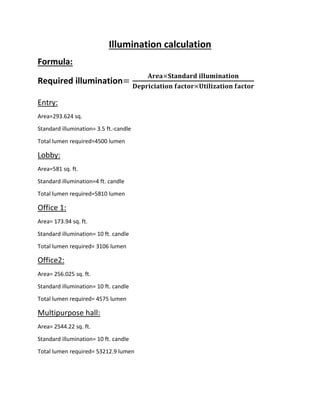
  • 1. Illumination calculation Formula: Required illumination= 𝐀𝐫𝐞𝐚×𝐒𝐭𝐚𝐧𝐝𝐚𝐫𝐝 𝐢𝐥𝐥𝐮𝐦𝐢𝐧𝐚𝐭𝐢𝐨𝐧 𝐃𝐞𝐩𝐫𝐢𝐜𝐢𝐚𝐭𝐢𝐨𝐧 𝐟𝐚𝐜𝐭𝐨𝐫×𝐔𝐭𝐢𝐥𝐢𝐳𝐚𝐭𝐢𝐨𝐧 𝐟𝐚𝐜𝐭𝐨𝐫 Entry: Area=293.624 sq. Standard illumination= 3.5 ft.-candle Total lumen required=4500 lumen Lobby: Area=581 sq. ft. Standard illumination=4 ft. candle Total lumen required=5810 lumen Office 1: Area= 173.94 sq. ft. Standard illumination= 10 ft. candle Total lumen required= 3106 lumen Office2: Area= 256.025 sq. ft. Standard illumination= 10 ft. candle Total lumen required= 4575 lumen Multipurpose hall: Area= 2544.22 sq. ft. Standard illumination= 10 ft. candle Total lumen required= 53212.9 lumen
  • 2. Pavement: Area= 2614.1 sq. ft. Standard illumination= 2.5 ft. candle Total lumen required= 10211.32 lumen Dinning Space: Area= 546.42 sq. ft. Standard illumination= 10 ft. candle Total lumen required= 11358.75 lumen Dinning space basin cabinet: Area= 28.2 sq. ft. Standard illumination= 5 ft. candle Total lumen required= 358.75 lumen Open space: Area= 150 sq. ft. Standard illumination= 5 ft. candle Total lumen required= 1562.5 lumen Corridor: Area= 348.42 sq. ft. Standard illumination= 5 ft. candle Total lumen required= 3629.4 lumen Pantry: Area= 95.63 sq. ft. Standard illumination= 5 ft. candle Total lumen required= 853.84 lumen
  • 3. Single Bed 1: Area= 98.4 sq. ft. Standard illumination= 10 ft. candle Total lumen required= 1537.5 lumen Single Bed 2: Area= 122.52 sq. ft. Standard illumination= 10 ft. candle Total lumen required= 1537.5 lumen Kitchen: Area= 217.82 sq. ft. Standard illumination= 20 ft. candle Total lumen required= 9075 lumen Pass way: Area= 174.695 sq. ft. Standard illumination= 5 ft. candle Total lumen required= 1819.74 lumen Dressing room (Gents): Area= 64.02 sq. ft. Standard illumination= 5 ft. candle Total lumen required= 666.875 lumen Toilet-1(Gents): Area= 22.64 sq. ft. Standard illumination= 5 ft. candle Total lumen required= 283 lumen
  • 4. Toilet-2(Gents): Area= 22.64 sq. ft. Standard illumination= 5 ft. candle Total lumen required= 283 lumen Dressing room (Ladies): Area= 64.02 sq. ft. Standard illumination= 5 ft. candle Total lumen required= 666.875 lumen Toilet-1(Ladies): Area= 21.32 sq. ft. Standard illumination= 5 ft. candle Total lumen required= 266.5 lumen Toilet-2(Ladies): Area= 21.32 sq. ft. Standard illumination= 5 ft. candle Total lumen required= 266.5 lumen Toilet: Area= 32.5 sq. ft. Standard illumination= 5 ft. candle Total lumen required= 406.25 lumen Store room: Area= 72.45 sq. ft. Standard illumination= 5 ft. candle Total lumen required= 754.68 lumen
  • 5. Circuit current & power calculation Distribution board 1 Circuit: (SB-1) Sl. No Specification Number of points Wattage per unit Wattage 1 Down light 3 25 75 2. Lobby Down light 4 25 100 3 Corridor Down light 1 20 20 4. 2 pin socket 1 100 100 Total 295 Max current=1.23 A Circuit: (SB-5) Max current: 3.75A Circuit: (SB-6) Max current: 4.02A Circuit: (SB-7) Sl. no Specification Number of points Wattage per unit Wattage 1. Tube light 6 40 240 2. fan 6 60 360 3. 2 pin socket 1 100 100 Total 700 Max current: 2.9A Sl. no Specification Number of points Wattage per unit Wattage 1. Tube light 6 40 240 2. Fan 6 60 360 3. 3 pin 2 100 200 4. 2 pin 1 100 100 5. Wall bracket 1 65 65 Total 960 Sl no Specification Number of points Wattage per unit Wattage 1. Tube light 6 40 240 2. Fan 6 60 360 3. 3 pin socket 1 100 100 4. 2 pin socket 1 100 100 Total 800
  • 6. Circuit: (SB-2): Sl. no Specification Number of points Wattage per unit Wattage 1. Tube light 1 40 40 2. Fan 1 60 60 3. 2pin socket 1 100 100 4. 3pin socket 1 100 100 Total 300 Max current=1.25A Circuit: (SB-3): Sl. no Specification Number of points Wattage per unit Wattage 1 Tube light 1 40 40 2 Wall bracket 1 25 25 3. Fan 2 60 120 4. 3pin socket 2 100 200 5. 2pin socket 1 100 100 Total 485 Max current= 2.02A Circuit: (SB-4): Sl. no Specification Number of points Wattage per unit Wattage 1 Down light 1 25 25 2 2pin socket 1 100 100 Total 125 Max current=0.5A Circuit: (SB-8) Sl. no Specification Number of points Wattage per unit Wattage 1 Wall bracket 1 25 25 Total 25 Max current=0.11A Circuit: (SB-9) Sl. no Specification Number of points Wattage per unit Wattage 1 Wall bracket 1 25 25 2 Down light 1 15 15 3 Fan 1 60 60 4 3 pin socket 1 100 100 5 2 pin socket 1 100 100 Total 300 Max Current = 1.25A
  • 7. Circuit: (SB-10) Sl. no Specification Number of points Wattage per unit Wattage 1 Air conditioner 1 6000 6000 Total 6000 Max current=25A Total current=41.34A Distribution Board 2 Circuit: (SB-11) Sl. no Specification Number of points Wattage per unit Wattage Sl. no 1 Tube light 1 40 40 0.16 2 Down light 2 65 130 3 Fan 4 60 240 4 3 pin socket 2 100 200 5 2 pin socket 1 100 100 Total 710 Max Current= 2.9A Circuit: (SB-12) Sl. no Specification Number of points Wattage per unit Wattage 1 Down light 1 9 9 2 Wall bracket 1 65 65 Total 74 Max Current = 0.31A Circuit: (SB-13) Sl. no Specification Number of points Wattage per unit Wattage 1 Down light 1 9 9 2 Wall Bracket 2 5 10 3 2 pin socket 1 100 100 Total 119 Max current = 0.5A Circuit: (SB-14) Sl. no Specification Number of points Wattage per unit Wattage 1 Down light 1 9 9 2 Wall Bracket 2 5 10 3 2 pin socket 1 100 100 Total 119 Max current = 0.5A
  • 8. Circuit: (SB-15) Sl. no Specification Number of points Wattage per unit Wattage 1 Wall bracket 2 65 130 2 Fan 1 60 60 3 Exhaust Fan 1 100 100 4 3pin socket 2 100 200 5 2 pin socket 1 100 100 Total 590 Max Current: 2.45A Circuit: (SB-16) Sl. no Specification Number of points Wattage per unit Wattage 1 Wall Bracket 1 15 15 2 Fan 1 60 60 3 3 pin socket 1 100 100 4 2 pin socket 1 100 100 Total 275 Max Current: 1.2A Circuit: (SB-17) Sl. no Specification Number of points Wattage per unit Wattage 1 Wall Bracket 1 15 15 2 Fan 1 60 60 3 3 pin socket 1 100 100 4 2pin socket 1 100 100 Total 275 Max Current: 1.15A Circuit: (SB-18) Sl. no Specification Number of points Wattage per unit Wattage 1 Wall Bracket 1 20 20 2 Fan 1 60 60 3 2 pin socket 1 100 100 Total 180 Max Current: 0.75A Circuit: (SB-19) Sl. no Specification Number of points Wattage per unit Wattage 1 Wall Bracket 1 5 5 2 Wall Bracket 1 20 20 3 Fan 1 60 60 4 2 pin socket 1 100 100 5 3 pin socket 1 100 100 Total 285 Max Current: 1.18A
  • 9. Circuit: (SB-20) Sl. no Specification Number of points Wattage per unit Wattage 1 Wall bracket 1 30 30 2 Fan 1 60 60 3 3 pin socket 1 100 100 4 2 pin socket 1 100 100 Total 290 Max Current = 1.2A Circuit: (SB-21) Sl. no Specification Number of points Wattage per unit Wattage 1 Wall bracket 1 25 25 2 Fan 1 60 60 3 3 pin socket 1 100 100 4 2 pin socket 1 100 100 Total 285 Max Current = 1.2A Total current=13.07A Summary table for power circuit Sl. no description Amperage Total Power circuit 1 Power circuit 2 (main board to sub main 1) 41.34 54.41 Power circuit 3 (main board to sub main 2) 13.07 Power circuit 2 Power circuit 4 1.23 41.34 Power circuit 5 1.25 Power circuit 6 2.02 Power circuit 7 .5 Power circuit 8 3.75 Power circuit 9 4.02 Power circuit 10 2.9 Power circuit 11 0.11 Power circuit 12 1.25 Power circuit 13 25 Power circuit 3 Power circuit 14 2.9 13.07 Power circuit 15 0.31 Power circuit 16 0.5 Power circuit 17 0.5 Power circuit 18 0.45 Power circuit 19 1.2 Power circuit 20 1.15 Power circuit 21 0.75 Power circuit 22 1.18 Power circuit 23 1.2 Power circuit 24 1.2
  • 10.
  • 11. Conduit Calculation From Conduit Layout we can see that, there are 21 (Twenty One) circuits in total. Specification as follows:  The Height of the Light Bracket from the Floor Level = 8 Feet.  The Height of the Switch from the Floor Level = 5 Feet.  The Height of the 3-pin Switch Board from the Floor Level = 2 Feet.  The Height of the Ceiling Fan from the Floor Level = 10 Feet. Main Board: 1. Main Board to Sub Main 1 = 4 ft. 2. Main Board to Sub Main 2 = 38.167 ft. Sub Main Board: 1. Sub Main 1 to SB-1= 35 ft. 2. Sub Main 1 to SB-2= 35.5 ft. 3. Sub Main 1 to SB-3= 25 ft. 4. Sub Main 1 to SB-4= 24.5 ft. 5. Sub Main 1 to SB-5= 41.58 ft. 6. Sub Main 1 to SB-6= 53.58 ft. 7. Sub Main 1 to SB-7= 65.58 ft. 8. Sub Main 1 to SB-8= 13 ft. 9. Sub Main 1 to SB-9= 13.08 ft. 10. Sub Main 1 to SB-10= 86.58 ft. 11. Sub Main 2 to SB-11=36ft 12. SB-11 to SB-12= 23 ft. 13. Sub Main 2 to SB-13= 22 ft. 14. Sub Main 2 to SB-14= 22 ft. 15. Sub Main 2 to SB-15= 27.58 ft. 16. Sub Main 2 to SB-16= 24 ft. 17. Sub Main 2 to SB-17= 13.33 ft. 18. Sub Main 2 to SB-18= 25 ft. 19. Sub Main 2 to SB-19= 29 ft. 20. Sub Main 2 to SB-20= 30 ft. 21. Sub Main 2 to SB-21= 27 ft.
  • 12. Table for SB wise conduit Sl. no Description Distance in ft. 1. SB-1 103.25 2. SB-2 33.167 3. SB-3 45.08 4. SB-4 8.416 5. SB-5 132 6. SB-6 120 7. SB-7 119 8. SB-8 5 9. SB-9 29.33 10. SB-10 5 11. SB-11 97.58 12. SB-12 20.84 13. SB-13 22 14. SB-14 22 15. SB-15 27.58 16. SB-16 24 17. SB-17 13.33 18. SB-18 25 19. SB-19 29 20. SB-20 30 21. SB-21 27 total 938.573
  • 13. Summary Table for Conduit calculation Serial no. Description Distance in Feet Total 1 Main Board to Sub Main 1 4 42.167 Main Board to Sub Main 2 38.167 2 Sub main 1 to SB-1 293.4 449.31 SB-2 SB-3 SB-4 SB-5 SB-6 SB-7 SB-8 SB-9 SB-10 SB-11 Sub main 2 to SB-12 155.91 SB-13 SB-14 SB-15 SB-16 SB-17 SB-18 SB-19 SB-20 SB-21 3 Switch board 938.573 938.573 total 1430.05 The Length of Total Conduit = 1430.05 ft. Considering 10% wastage, The Length of Total Conduit = 1573.055 ft.
  • 14. Wire calculation Sl. no Board specification Distance in feet Cost per unit Cost 1 SB-1 1/1.40 mm 182 6.1874 1126.107 2 SB-2 1/1.40 mm 51.5 6.1874 318.6511 3 SB-3 1/1.40 mm 146.84 6.1874 908.5578 4 SB-4 1/1.40 mm 8.42 6.1874 52.09791 5 SB-5 1/1.40 mm 383.5 6.1874 2372.868 6 SB-6 1/1.40 mm 352 6.1874 2177.965 7 SB-7 1/1.40 mm 309 6.1874 1911.907 8 SB-8 1/1.40 mm 5 6.1874 30.937 9 SB-9 1/1.40 mm 29.33 6.1874 181.4764 10 SB-10 1/3.55mm 86.58 23.37 2023.375 11 SB-11 1/1.40 mm 211.16 6.1874 1306.531 12 SB-12 1/1.40 mm 23.84 6.1874 147.5076 13 SB-13 1/1.40 mm 16.84 6.1874 104.1958 14 SB-14 1/1.40 mm 16.84 6.1874 104.1958 15 SB-15 1/1.40 mm 83.94 6.1874 519.3704 16 SB-16 1/1.40 mm 18 6.1874 111.3732 17 SB-17 1/1.40 mm 33 6.1874 204.1842 18 SB-18 1/1.40 mm 13.94 6.1874 86.25236 19 SB-19 1/1.40 mm 34.416 6.1874 212.9456 20 SB-20 1/1.40 mm 38 6.1874 235.1212 21 SB-21 1/1.40 mm 20.84 6.1874 128.9454 22. Main board to sub main 1 7/1.70 mm 8 52.169 417.352 23 Main board to sub main 2 1/1.80 mm 76.32 9.43 359.8488 Total 2149.306 15041.76 Total neutral wire required=1235.16 ft. Cost of neutral wire (1/1.40mm)=1235.16×6.1874=7642.42TK Summary table for wire cost Specification Required length Required length with 10% wastage Cost per unit cost 1/1.40 mm 3213.566 3534.9226 6.1874 21871.98 1/3.55 mm 86.58 95.238 23.37 2225.712 7/1.70 mm 8 8.8 52.169 459.087 1/1.80 mm 76.32 83.96 9.43 791.7428 Total 2534.52186
  • 15.
  • 16. Cost calculation Wire and conduit cost Item Specification Total unit(ft.) Cost (per ft.) Cost (TK) Wire (PVC insulated and PVC sheathed) 1/1.40 mm 3534.9226 6.1874 21871.98 1/3.55 mm 95.238 23.37 2225.7 7/1.70 mm 8.8 52.169 459.0872 1/1.80 mm 83.96 9.43 791.7428 Conduit 1573.055 10.49 16501.346 Total 41849.86 Accessories cost Sl. no Material used Quantity Rate(Tk/piece) Cost 1. Tee 30 6 180 2. Elbow 46 3 138 3. Circular box 15 6 90 4. Junction box 10 6 60 5. Surface mounting plastic box 21 145 3045 6. Lamp holder 32 55 1760 7. Tube stand 21 150 3150 8. Switch board 21 198 4158 9. Switch 102 35 3570 10. Fuse 21 35 735 11. 2 pin Socket(6A) 21 35 735 12. 3 pin socket(6/16A) 16 175 2800 13. Screw 388 0.5 194 14. Distribution board 2 800 1600 15. Fan regulator(% steps) 33 580 19140 16. Mini circuit breaker 11 260 2860 17. Ceiling rose 57 35 1995 18. Fire alarm 1 1200 1200 19. Indicator lamp 21 80 1680 20. Rubber Tape 12 18 216 21. Royal plug 388 .25 97 Total 46703
  • 17. Labor cost Total no. of load and plug point=102 Labor cost=110 TK/load and plug point So, total labor cost=110×102= 11220 TK. Summary of cost calculation Cost specification Cost(TK) Wire and conduit cost 41849.86 Accessories cost 46703 Labor cost 11220 Total Cost 99772.86 The total cost for “KUET GUEST HOUSE – Ground floor” wiring is 99,775TK.