Transmission Line Design and Selection of Parameters for Economical Power Transmission
•
2 likes•1,813 views

200MW power transmission and 100 km length of transmission

Recommended
More Related Content
What's hot
What's hot (20)
Similar to Transmission Line Design and Selection of Parameters for Economical Power Transmission
Similar to Transmission Line Design and Selection of Parameters for Economical Power Transmission (20)
Recently uploaded
Recently uploaded (20)
Transmission Line Design and Selection of Parameters for Economical Power Transmission
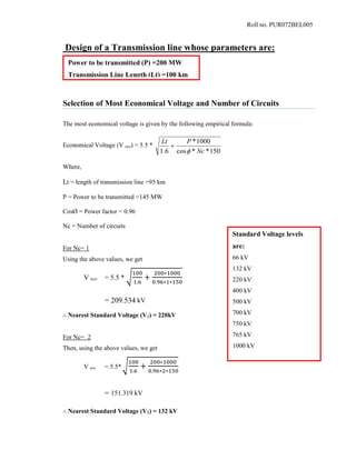
- 1. Roll no. PUR072BEL005 Design of a Transmission line whose parameters are: Selection of Most Economical Voltage and Number of Circuits The most economical voltage is given by the following empirical formula: Economical Voltage (V eco) = 5.5 * 150**cos 1000* 6.1 Nc PLt Where, Lt = length of transmission line =95 km P = Power to be transmitted =145 MW CosØ = Power factor = 0.96 Nc = Number of circuits For Nc= 1 Using the above values, we get V eco = 5.5 * √ 100 1.6 + 200∗1000 0.96∗1∗150 = 209.534 kV ∴ Nearest Standard Voltage (V1) = 220kV For Nc= 2 Then, using the above values, we get V eco = 5.5*√ 100 1.6 + 200∗1000 0.96∗2∗150 = 151.319 kV ∴ Nearest Standard Voltage (V2) = 132 kV Power to be transmitted (P) =200 MW Transmission Line Length (Lt) =100 km Standard Voltage levels are: 66 kV 132 kV 220 kV 400 kV 500 kV 700 kV 750 kV 765 kV 1000 kV
- 2. Roll no. PUR072BEL005 Checking Technical Criterion Surge Impedance Loading (SIL): For Nc =1, Characteristic Impedance (Zc) =400 Ω SIL1 = 𝑉12 𝑍𝑐 = 2202 400 = 121 MW For Nc =2, Characteristic Impedance (Zc) = 200 Ω SIL2 = 𝑉22 𝑍𝑐 = 1322 400 = 87.12 MW Calculation of Multiplying factor (Mf): For Nc=1, Mf1 = 𝑃 𝑆𝐼𝐿1 = 200 121 = 1.653 For Nc=2, Mf2 = 𝑃 𝑆𝐼𝐿2 = 200 87.12 = 2.296 From Table, for 100 Km line length, Mflimit of the line lies between 2.25 and 2.75. Therefore, using interpolation to find Mflimit for 100km, we have Mf𝑙𝑖𝑚𝑖𝑡 = 2.75 + 2.25 − 2.75 160 − 80 (95 − 80) = 2.625 Decision: Here, Mf1<Mf𝑙𝑖𝑚𝑖𝑡 and Mf2<Mf𝑙𝑖𝑚𝑖𝑡 . Here both are technically feasible. However the mf margin for Nc=1 is 0.972 and for Nc=2 is 0.329. Since, mf margin for Nc=2 is lower, we select double circuit. Thus, Line Length (km) Mflimit 80 2.75 160 2.25 240 1.75 320 1.35 480 1.0 640 0.75 Voltage Level for given Power Transmission =132 kV Number of Circuits (Nc) = 2 Power factor (cosφ) = 0.96
- 3. Roll no. PUR072BEL005 Air Clearance and Conductor Spacing Calculation 1) Minimum air clearance required from earthed object is given by 𝒂 = 𝑉𝑟𝑚𝑠 × 1.1 √3 + 30 𝑐𝑚 = 132 ∗ √2 × 1.1 √3 + 30 = 148.55 𝑐𝑚 = 1.48 m 2) Maximum String Swing (ɵmax) = 450 3) Length of string or insulator hanging (l) = a Secɵmax= 148.55 * Sec450 = 210.08 cm =2.10 m ∴l=2.10 m 4) Cross arm length (CL) = a (1+tanɵmax) = 148.55 * (1+ tan 450 ) = 297.1 cm ∴CL = 297.1 cm = 2.97 m 5) Vertical distance between two adjacent line conductor (y) = 22 1 )( CL al y x al Where, 0.25 < x/y< 0.333 Lets take x/y = 0.3 y = 210.08+148.55 √1−(0.3)2( 210.08+148.55 297.1 ) 2 = 384.74 𝑐𝑚 ∴Distance between two conductors(y) = 3.84 m 6) x= y * 0.3 = 3.84 m * 0.3 = 1.15 m ∴ x= 1.15 m 7) Width of tower (b) = 1.5a = 1.5* 1.48 = 2.22 m ∴ b = 2.22 m 8) Distance between the earth wire and the topmost cross-arm for double circuit: d= √3 ∗ 𝐶𝑙 − 𝑙 = √3 ∗2.97– 2.10 = 3.04 m ∴ d = 3.04 m 9) Right of way (ROY) = 2*CL + b = 2* 2.97 + 2.22 = 8.16 m
- 4. Roll no. PUR072BEL005 Therefore, height of tower = h +2 y + d = Hg + s + 2y + d where, Hg = minimum ground clearance = 6.1 + s + 2 * 3.84 + 3.04 And s = sag of the conductor = (16.82 + s) m Selection criteria for number of earth wire Voltage levels No. of circuits (Nc) Number of earth wire (Ne) 66 kV *(1/2) 1 132 kV 1 2 1 2 220 kV 1 2 1 2 ≥ 400 kV 2 *(1/2) 2 2 From above table, for double circuit of 132 kV, number of earth wire is 2 Air Clearance from Earthed Object (a) = 1.48 m Length of String (l)= 2.10 m Cross arm Length (CL) = 2.97 m Width of Tower (b) = 2.22 m Vertical Distance between two adjacent line conductors (y) = 3.84 m Height of Earth Wire from Top Most Cross arm (d) = 3.04 m Horizontal Distance between Two adj. line conductors Or Right of Way (2Cl+b) = 8.16 m Thus, number of earth wire(Ne) =2 is selected.
- 5. Roll no. PUR072BEL005 Number of Disc Selection For all the calculations of number of insulator discs of size 254 *154 mm, we considered following value of different factors: FOWR= Flashover Withstand Ratio = 1.15 NACF = Non-Standard Atmospheric Condition factor =1.1 FS = Factor of Safety=1.2 Here, System Voltage = 132 kV and Max. System voltage = 145.2 kV a. 1 minute Dry Test Equivalent Flashover Voltage = 1 min. dry withstand voltage * FOWR * NACF * FS Where, 1 min. dry withstand voltage is given in table A-2 for 145.2 kV system voltage = 265 kV ∴Equivalent FOV = 265 * 1.15 * 1.1 * 1.2 = 402.27 kV Nearest higher 1 min. dry FOV voltage (in table A-3) = 435 kV From table A-3, for 1 minute dry FOV = 435 kV, no. of discs = 7 ∴No. of disc = Nd1 = 7 b. 1 minute Wet Test Equivalent FOV = 1 min. wet withstand voltage * FOWR * NACF * F S Where, 1 min. wet withstand voltage is given in table A-2 for 145.2 system voltage = 230 kV ∴Equivalent FOV = 230 * 1.15 * 1.1 * 1.2 = 349.14 kV Nearest higher 1 min. wet FOV voltage (in table A-3) = 370 kV. From table A-3, for 1 minute dry FOV = 370 kV, no. of discs = 9 ∴ No. of discs = Nd2 = 9 c. Temporary Over Voltage Test Temporary o/v = EF * maximum system voltage Where, EF = Earthing Factor = 0.8 (for Nepal) ∴Temporary o/v = 0.8 * 145.2 = 116.16 kV Equivalent FOV = Temporary o/v * √2 * FOWR * NACF * FS = 116.16 * √2 * 1.15 * 1.1 * 1.2
- 6. Roll no. PUR072BEL005 = 249.3695 kV Wet season is the worst condition. Thus, nearest higher FOV (from table A-3, 1 min. wet FOV) =250 kV ∴No. of discs = Nd3 = 6 d. Switching Over Voltage Test Switching o/v = Maximum per phase peak voltage * SSR Where, SSR = Switching Surge Ratio = 2.8 ∴Switching o/v = 132 * √2 √3 * 1.1* 2.8 = 331.49 kV Equivalent s/w FOV = Switching o/v * SIR * FOWR * NACF * FS Where, SIR = Switching to Impulse Ratio = 1.2 Equivalent FOV = 331.49 * 1.2 * 1.15 * 1.1 * 1.2 = 603.8 kV The nearest higher voltage (in table A-3, impulse FOV) = 610 kV ∴No. of discs = Nd4 = 6 e. Lightening Over Voltage Test Equivalent impulse withstand o/v = 550 kV (from table A-2) for 145.2 kV Equivalent impulse FOV = Equivalent impulse withstand voltage * FWR * NAC * FS = 550 * 1.15 * 1.1 * 1.2 = 834.9 kV The nearest higher voltage (in table A-3, impulse FOV) = 860 kV ∴No. of discs = Nd5 = 9 S.N. Test No. of Discs a. 1 min. Dry Test 7 b. 1 min. Wet Test 9 c. Temporary O/V Test 6 d. Switching O/V Test 6 e. Lightening O/V Test 9 From the table, it is seen that the minimum no. of disc required to withstand all tests is 9. ∴ The No. of discs required for our design (Nd) is 9.
- 7. Roll no. PUR072BEL005 Conductor Selection I. Continuous Current Carrying Capability/ P = 200 MW, Nc = 2, VL = 132 kV, Cosφ = 0.96 Line current is calculated as: Line current (IL) = cos**3 / llV NcP = 200∗10^6/2 √3∗132∗10^3∗0.96 = 455.611 A Comparing this value of the current with the current carrying capacity from the given standard ASCR conductor table, the conductor “LYNX” (with current carrying Capacity 475 A) is selected. II. Transmission Efficiency Criterion For LYNX conductor, From ASCR conductor table, Resistance at 200 C (R20) = 0.15890 Ώ/Km Coefficient of Resistivity (α20) =0.004 /0 C (For Aluminum) So Resistance at 650 C (R65) = R20 (1 +α20(65-20)) = 0.15890(1+0.004*45) = 0.187502 Ώ/Km Total Resistance of the line for 95 Km = 18.7502 Ώ ∴Total Power Loss (PL) = 3* IL 2 *R65 * Nc = 3* 455.6112 *18.7502*2 = 23.3532 MW ∴ɳ = 1- 𝑃𝑙 𝑃 = 1- 25.3532 200 = 88.3234 % This efficiency is <94%. So this conductor cannot be used. To get the higher efficiency we proceed in the same way and calculate efficiency for SHEEP as shown below. For SHEEP conductor, From ASCR conductor table, Resistance at 200 C (R20) = 0.07771 Ώ/Km Coefficient of Resistivity (α20) =0.004 /0 C (For Aluminum) So Resistance at 650 C (R65) = R20 (1 +α20(65-20))
- 8. Roll no. PUR072BEL005 = 0.07771 (1+0.004*45) = 0.0916978 Ώ/Km Total Resistance of the line for 95 Km = 9.16978 Ώ ∴Total Power Loss (PL) = 3* IL 2 *R65 * Nc = 3* 333.792 *9.16978*2 = 11.421 MW ∴ɳ = 1- 𝑃𝑙 𝑃 = 1 – 11.421 200 = 94.2895% Thus, this efficiency is >94% (i.e. 94.21%). So we select the conductor BEAR. Conductor R20(Ώ/Km) R65 (Ώ/Km) Ploss (MW) ɳ (%) Remarks LYNX 0.15890 0.187502 23.3532 88.3234 <94% SHEEP 0.07771 0.0916978 11.421 94.2895 >94% III. Voltage Regulation Criterion The SHEEP conductor has 37 strands (30 Aluminum strands and 7 steel strands). Diameter of conductor (D) =27.93mm Radius of the conductor(R) =13.965mm GMR for inductance (r’) =0.768R =0.768 * 13.965 =10.72512mm = 1.073 cm GMR for capacitance (r) = R = 13.965 mm. = 1.3965 cm Here, Vertical distance between two conductors (y) = 3.84m Cross arm length (CL) = 2.97 m Width of tower (b) = 2.22 m Horizontal distance between two conductors (2*CL + b) = 8.16 m (i.e. ROY)
- 9. Roll no. PUR072BEL005 Fig. Double Circuit Line Representation i.e. Dacˈ =8.16 m = Dca’= Dbbˈ = Da’c = Db’b = Dc’a Dab’= √(𝐷𝑎𝑐′)2 + (𝑦)2= √8.162 + 3.842 = 9.018 m=Dba’=Dbc’=Dcb’ Dca = 2*3.84 = 7.68 m= Dc’a’ Dab=3.84 m= Dbc= Db’a’= Db’c’ Daaˈ=√(𝐷𝑎𝑐′)2 + (2𝑦)2= √8.162 + (2 ∗ 3.84)2 = 11.2 m = Dccˈ For GMD Calculation: GMD = (Dab .Dab' . Da'b .Da'b' .Dbc .Dbc'.Db'c .Db'c' .Dca .Dca' . Dc'a .Dc'a')1/12 = ( 3.84*9.018*9.018*3.84*3.84*9.018*9.018*3.84*7.68*8.16*8.16*7.68)1/12 ∴GMD=6.496 m For GMR Calculation: Here, for GMRL, r’=0.768R = 0.9 cm Dsa= √𝐷𝑎𝑎 ∗ 𝐷𝑎𝑎′ ∗ 𝐷𝑎′ 𝑎′ ∗ 𝐷𝑎′𝑎 4 =√𝐷 𝑎𝑎′ ∗ 𝑟′ = √11.2 ∗ 9 ∗ 10^(−3) = 0.3174m=31.74 cm Dsb = √𝐷𝑏𝑏 ∗ 𝐷𝑏𝑏′ ∗ 𝐷𝑏′ 𝑏′ ∗ 𝐷𝑏′𝑏 4 = √𝐷 𝑏𝑏′ ∗ 𝑟′ = √8.16 ∗ 9 ∗ 10^(−3) =0.2709m=27.09 cm Dsc = √𝐷𝑐𝑐 ∗ 𝐷𝑐𝑐′ ∗ 𝐷𝑐′ 𝑐′ ∗ 𝐷𝑐′𝑐 4 = √𝐷𝑐𝑐′ ∗ 𝑟′ = √11.2 ∗ 9 ∗ 10^(−3) = 0.3174m= 31.74 cm ∴GMRL =√𝐷𝑠𝑎 ∗ 𝐷𝑠𝑏 ∗ 𝐷𝑠𝑐 3 =√31.74 ∗ 27.09 ∗ 31.74 3 = 30.107 cm
- 10. Roll no. PUR072BEL005 For GMRc, Here, for GMRC, r=R=11.725 mm=11.725*10-3 m Dsa= √𝐷𝑎𝑎 ∗ 𝐷𝑎𝑎′ ∗ 𝐷𝑎′ 𝑎′ ∗ 𝐷𝑎′𝑎 4 =√ 𝐷 𝑎𝑎′ ∗ 𝑟 = √11.2 ∗ 11.725 ∗ 10^(−3) =0.3623 m =36.23cm Dsb = √𝐷𝑏𝑏 ∗ 𝐷𝑏𝑏′ ∗ 𝐷𝑏′ 𝑏′ ∗ 𝐷𝑏′𝑏 4 = √ 𝐷 𝑏𝑏′ ∗ 𝑟 = √8.16 ∗ 11.725 ∗ 10−3 =0.3093m =30.93 cm Dsc = √𝐷𝑐𝑐 ∗ 𝐷𝑐𝑐′ ∗ 𝐷𝑐′ 𝑐′ ∗ 𝐷𝑐′𝑐 4 = √ 𝐷𝑐𝑐′ ∗ 𝑟 = √11.2 ∗ 11.725 ∗ 10^(−3) =0.3623m=36.23cm ∴ GMRC=√ 𝐷𝑠𝑎 ∗ 𝐷𝑠𝑏 ∗ 𝐷𝑠𝑐 3 =√36.23 ∗ 30.93 ∗ 36.23 3 = 34.36 cm Now, Inductance per unit length (L) = 2 ∗ 10−7 ∗ ln ( 𝐺𝑀𝐷 𝐺𝑀𝑅 𝐿 ) H/m = 2 ∗ 10−7 ∗ ln ( 6.496∗100 30.107 ) = 6.143*10-7 H/m = 6.143*10-7 *103 *103 =0.6143 mH/km ∴Capacitance per unit Length(C) = 2𝜋𝜀 ln( 𝐺𝑀𝐷 𝐺𝑀𝑅𝑐 ) ∗ 1000 𝐹/𝑘𝑚 [Ɛ0 = 8.85*10-12 F/m] = 2𝜋∗8.85∗10−12 𝑙𝑛( 6.496∗100 34.36 ) ∗ 1000 = 1.891*10-8 F/km ∴Capacitance per unit length = 1.891*10−8 F/km Resistance of whole length = 12.255 Ώ ∴ Resistance per unit length = 0.12255 Ώ/Km Impedance of the line (Z) = R65 + j XL =R+j(2π*f*L ) = (0.12255+j*(2π*50*6.143*10-4 ) ) [f=50 Hz] = (0.12255 +j 0.1929) Ω/km =(0.12255 +j 0.1929) * 100 Ω =12.255+j 18.333 Ω
- 11. Roll no. PUR072BEL005 = 22.051∠𝟓𝟔. 𝟐𝟑 0 Ω Susceptance of the line (Y) = j w C = j*2π*50*1.891 *10-8 *95= j 5.643 *10-4 Siemens = 5.643*10-4 ∠900 Siemens Calculation of ABCD parameters Since 100 km line length lies on medium Transmission line (i.e. 50 –200 km), Calculation of parameters is done Using π-model. Fig: Nominal π- model of T.L. 𝐀 = 𝐃 = 1 + YZ 2 = 1 + 5.643 ∗ 10−4 ∠900 ∗ 22.051∠56.230 2 = 𝟎. 𝟗𝟗𝟒∠𝟎. 𝟏𝟗𝟗° = 𝟎. 𝟗𝟗𝟒 + 𝐣𝟑. 𝟒𝟓𝟖 𝐁 = Z =22.051 ∠ 56.23 𝐂 = Y (1 + YZ 4 ) = 5.643 ∗ 10−4 ∠900 (1 + 5.643 ∗ 10−4 ∠900 ∗ 22.051∠56.230 4 ) = −𝟗. 𝟕𝟓𝟕 ∗ 𝟏𝟎−𝟕 + 𝐣𝟓. 𝟔𝟐𝟖 ∗ 𝟏𝟎−𝟒 = 𝟓. 𝟔𝟐𝟖 ∗ 𝟏𝟎−𝟒 ∠𝟗𝟎. 𝟎𝟗° ∴| 𝐼 𝑅| @ full load = 333.79 A Cos Φ = 0.95(lag) ∴Φ = -18.190 Then, IR =333.79∠-18.19 A ∴VR per phase @ full load = 132 √3 ∗ 𝟏𝟎𝟎𝟎 ∠ 00 = ( 𝟕𝟔𝟐𝟏𝟎∠𝟎°)V ∴|VR| per phase @ full load = 76210 V = 76.21 kV Therefore, Sending end voltage is given by ∴ VS (per phase) @ full load = A VR + B IR =(0.994∠0.199°)*( 76210∠0°) +(22.051 ∠ 56.23)*333.79∠−18.190 = 𝟖𝟏𝟓𝟒𝟗. 𝟏𝟗 + 𝒋 𝟒𝟕𝟗𝟖. 𝟔𝟔 VS VR IR Y/2 ZIS Y/2 2
- 12. Roll no. PUR072BEL005 = 81690.25∠3.36 V = 81.69 ∠ 3.36 kV Hence, |VR| per phase @ no load = | 𝑉𝑠 @ 𝑓𝑢𝑙𝑙 𝑙𝑜𝑎𝑑 𝐴 | = | 81.69 0.994 | = 82.18 kV ∴Voltage Regulation (V.R.) = | 𝑉𝑟@ 𝑛𝑜 𝑙𝑜𝑎𝑑|−|𝑉𝑟 @ 𝑓𝑢𝑙𝑙 𝑙𝑜𝑎𝑑| |𝑉𝑟 @ 𝑓𝑢𝑙𝑙 𝑙𝑜𝑎𝑑| = 82.18−76.21 76.21 = 7.83 % Since calculated voltage regulation < 12 %, the conductor SHEEP satisfies voltage regulation criterion. IV. Corona Inception Voltage Criterion For BEER conductor, Maximum system voltage = 132 * 1.1 = 145.2 kV (rms) Corona inception voltage (Vci) = √3 ∗ Air dielectric strength * GMRC * m * δ * 𝑙𝑛 ( 𝐺𝑀𝐷 𝐺𝑀𝑅𝑐 ) Where, Air dielectric strength = 21.21 kV/ cm (rms) GMRc = 34.36 cm GMD = 649.6 cm m = Roughness factor = 0.9 δ = Relative density of air = 0.95 ∴Vci= √3 ∗ 21.21 * 34.36 * 0.9 * 0.95 * 𝑙𝑛 ( 649.6 34.36 )= 3170.909 kV Since Vci> Maximum system voltage (145.2 kV), there is no corona effect on BEER conductor. So, Corona Inception Voltage criterion is satisfied and all the technical criteria is met by BEER conductor. Hence the best five conductors which satisfy all the criteria are: Thus, the conductor SHEEP can be used for our design. 1. SHEEP 2. DEER 3. ZEBRA 4. ELK 5. MOOSE
- 13. Roll no. PUR072BEL005 Tension Calculation for Different Conductors 1. Toughest condition -T1 tension and Sag is minimum (Dmin). - Wt. of conductor (w1) 2. Normal Operating Condition (Stringing Condition) – T2 tension and S2 sag - Wt. of conductor (w2) 3. Easiest condition – T3 tension and Sag is maximum (Dmax). - Wt. of conductor (w3) Let wc = weight of conductor per unit length ww = weight per unit length due to wind wice= weight per unit length due to ice ∴ Weight during toughest condition = w1 = √(𝑤𝑐 + 𝑤𝑖𝑐𝑒)2 + 𝑤 𝑤 2 Calculation of Tension @ toughest condition (T1) T1≤ 𝑈𝑇𝑆 𝐹𝑆 where, UTS = Ultimate Tensile Strength of the conductor FS = Factor of safety = 2 Calculation of Tension at Normal condition (T2) T2 is given by stringing equation T2 2 (T2 + k1) – k2 = 0 Where, k1 = -𝑇1 + α (θ2 – θ1) A ϵ + 𝑤1 2 𝑙2 24 𝑇1 2 Aϵ k2 = 𝑤2 2 𝑙2 24 Aϵ ϵ= Modulus of Elasticity α= Coefficient of linear expansion A = Cross-section area of conductor θ2 = Temperature at normal condition = 270 C θ1 = Temperature at toughest condition = 00 C w1 = per unit length conductor weight @ toughest condition w2 = per unit length conductor weight @ stringing condition Calculation of Tension @ Easiest condition (T3) wc + wice ww w1
- 14. Roll no. PUR072BEL005 T3 is given by Stringing equation T3 2 (T3 + k1’) – k2’= 0 Where, k1’ = -T2 + α (θ3 – θ2) A ϵ + 𝑤1 2 𝑙2 24 𝑇2 2 Aϵ k2’ = 𝑤2 2 𝑙2 24 Aϵ = k2 θ3 = Temperature @ easiest condition = 650 C Now, we perform tension calculation for conductors “SHEEP,DEER,ZEBRA,ELK,MOOSE” with Span length 250 m, 275 m, 300 m, 325 m, and 350 m. The Tensions for Toughest, Stringing (Normal) and Easiest condition are calculated and tabulated below. Sample Calculation For SHEEP Conductor Area of conductor (A) = 462.60 mm2 Coefficient of linear expansion (α) = 17.73*10-6 /0 C Modulus of Elasticity (ε) = 0.789*106 kg/cm2 Ultimate Tensile Strength (UTS) = 15910 kg Wt. of conductor per unit length (wc) = 1726 kg/km Wind Pressure (wp) = 100 kg/m2 Conductor diameter (d) = 27.93 mm Thickness of ice (t) = 10 mm = 0.01 m ؞Wt due to wind (ww) per km = (wp*1000)*(d*2/3) kg/km = 100*1000*27.93*10-3 *2/3 = 1862kg/km Wt due to ice loading (wi) = π t (d+t) ρice *1000 kg/km = π * 0.01 (0.02345+0.01)* 950 *1000 = 998.31 kg/km ؞Wt. @ Toughest condition (w1)= √(𝑤𝑐 + 𝑤𝑖)2 + 𝑤 𝑤 2 = √(17262 + 18262 = 25838.921 kg/km ؞ Wt. @ Stringing Condition (w2) = wc = 1726 kg/km ؞Wt. @ Easiest Condition (w3) = wc = 1726 kg/ km
- 15. Roll no. PUR072BEL005 Temperature @ Toughest condition (ɵ1) = 00 C Temperature @ Normal Condition (ɵ2) = 270 C Temperature @ Easiest Condition (ɵ3) = 650 C Calculation of T1 T1 = 𝑈𝑇𝑆 𝐹𝑆 = 15910 2 = 7955kg ( since, T1=110.9kN=11316.3kg) Calculation of T2 k1 = -T1 + α (θ2 – θ1) A ϵ + 𝑤12 𝑙2 24 𝑇12 Aϵ k2 = 𝑤22 𝑙2 24 Aϵ From stringing equation, T2 2 (T2 + k1) – k2 = 0 or, T2 3 + k1 T2 2 – k2 = 0 or, T2 3 -5239.54 T2 2 – 2.831*1010 = 0 ∴T2= 6020.697 kg Calculation of T3 k1’ = -T2 + α (θ3 – θ2) A ϵ + 𝑤12 𝑙2 24 𝑇22 Aϵ = -1871.33 k2’ = k2 = 2.8316*1010
- 16. Roll no. PUR072BEL005 From String’s equation, T3 2 (T3 + k1’) – k2’ = 0 or,T3 3 +k1’T3 2 – k2’ = 0 or,T3 3 – 2.831*1010 =0 or, T3 = 3815.932 kg Hence, five best conductors have been chosen. The tension due to these five different conductors for different span length from 250m to 350m (step of 25m) are shown in the following tables :
- 17. Roll no. PUR072BEL005 Sag and Tower Height Calculation The maximum sag between two towers is given by Dmax = 𝑤3𝑙𝑠 𝑝2 8𝑇3 Where, w3= weight of conductor per unit length @ easiest condition. Lsp = Span length T3 = Tension @ easiest condition. Minimum ground clearance = hg = ( 𝑉𝑠𝑚𝑎𝑥−33) 33 + 17 𝑓𝑒𝑒𝑡 Where, Vsmax= Maximum system voltage. Now, Height of lowest conductor = h1 = hg + Dmax Height of middle conductor = h2 = h1 + y [For Nc=2] Height of topmost conductor = h3 = h2 + y Height of tower = ht = h3 + d’ From air clearance section, we have d’ =distance between earth wire and topmost power conductor = 3.04 m y= vertical distance between two conductors = 3.84m
- 18. Roll no. PUR072BEL005 Vsmax= 132*1.1 =145.2 kV hg= (145.2−33) 33 + 17 𝑓𝑒𝑒𝑡 = 20.4 ft. = 6.21792 m Sample Calculation For SHEEP Conductor w3 = wt. per unit length @ easiest condition = 1219 kg/km. (=w2 in table 1.1) lsp= 250m = 0.25 km (assume) T3 = 1684.78 kg (from table 1.1) = 3.533m ∴ h1 = hg + Dmax = 6.21792+3.533= 9.75092 m h2 = h1 + y = 9.75092+2.00967 = 11.76059m h3 = h2 + y = 13.77026 m ht = h3+d’ = 19.2687 m Similarly, the maximum sag, h1, h2, h3 and the total height of the tower for different span lengths for five best conductors are calculated and presented in the table shown here:
- 19. Roll no. PUR072BEL005 Earth Wire Selection From earth wire table, earth wire GUINEA is chosen as follows: No of strands = 19 Diameter of a strand = 2.92mm Weight of conductor = 590kg/km Diameter of earth wire (de) = 14.60mm Area of Conductor = 127.20mm2 Ultimate tensile strength = 6664 kg Hence, maximum tension (T1e) = 3332 kg
- 20. Roll no. PUR072BEL005 Bending Moment and Tower Weight Calculation For design purpose, we consider 80% of the towers are of class A, 15% of the towers are of class B and 5% of the towers are of class C. The bending moment acting on the tower are due to the followings: wind force on power conductor (BMPw) wind force on earth wire (BMEw) Turning of power conductor (BMPT) Turning of earth conductor (BMET). Sample Calculation For SHEEP and span length (lsp) = 250m a. BM due to power conductor BM due to wind force (BMPw) = Fwp * (h1+h2+h3)*Nc Where, Fwp = Wind force =wp * dp * lsp * 2/3 wp = Wind pressure = 100kg/m2 dp = diameter of power conductor = 27.93 mm = 27.93*10-3 m h1 = height of bottom most conductor = 9.75162m (table 2.1) h2 = height of middle conductor = 11.76129m (table 2.1) h3 = height of top most conductor = 13.77096 m (table 2.1) Nc = No. of circuits = 1 lsp = span length = 250m ∴ BMPw = wp* dp*lsp* 2/3* (h1+h2+h3)*Nc = 100*27.93*10-3 *250*2/3*(9.75162 +11.76129 +13.77096)*2 = 32847.32787 kgm
- 21. Roll no. PUR072BEL005 BM due to turning (BMPt) = 2*T1*(0.8 sin10 +0.15 sin7.50 + 0.05 sin 150 )*(h1+h2+h3)*Nc Where, T1 = Tension @ toughest condition = 7955kg (table 1.1) ∴ BMPt = 2*7955*(0.8 sin10 +0.15 sin7.50 + 0.05 sin 150 )* (9.75162 +11.76129 +13.77096)*2 = 15910* 0.046482* 35.28177*2 = 52183.7574 kgm. b. BM due to earth wire BM due to wind force (BMEw) = Fwe * ht * Ne = wp*de*lsp*2/3*ht*Ne Where, Fwe = Wind force on earth conductor Wp = wind pressure = 100kg/m2 de = Diameter of earth conductor = 14.60 mm = 14.60*10-3 m (for GUINEA) lsp = Span length = 250m ht = tower height = 19.26933m (from table 2.1) Ne = No. of earth wire = 1 ∴ BMEw = 100*14.60* 10-3 *250*2/3*19.26933*2 = 93774.434 kgm BM due to turning (BMEt) BMEt = 2 T1e*(0.8 sin10 +0.15 sin7.50 + 0.05 sin 150 )*ht*Ne Where T1e = Tension on earth conductor @ toughest condition T1e = UTS of GUINEA /2 = 6664/2 = 3332 kg ∴ BMEt = 2*3332*(0.8 sin10 +0.15 sin7.50 + 0.05 sin 150 )*19.26933*2 = 11937.193 kgm ∴ Total Bending Moment (TBM) = BMPw+BMPt+BMEw+BMEt = 106345.7123 kgm ∴ Tower weight (TW) Where FS = Factor of Safety = 2
- 22. Roll no. PUR072BEL005 ∴ TW = 0.000631*19.26933*√𝟏𝟎𝟔𝟑𝟒𝟓. 𝟕𝟏𝟐𝟑 ∗ 𝟐 = 5.60734 tonnes Similarly, we can calculate the total bending moment and tower weight for different conductors at different span length:
- 23. Roll no. PUR072BEL005 Tower Cost per Unit Length Calculation Assumptions: Cost of steel = Rs 1, 50,000 per tonnes No. of towers = + 1 = Nt [Lt = Total Length and lsp = Span length] ∴Cost of tower per unit length = Cost per tower * Nt /Lt Sample Calculation For SHEEP and for span length = 250m lsp = 250m Lt = 100 km Tower weight (TW) = 5.60734 tonnes (from table 3.1) Cost per tower = cost per tonne ∗ weight of tower = 1, 50,000 *5.60734 =Rs. 841101 Cost of tower per unit length = Cost per tower * Nt / Lt = 841101*401/100 = Rs. 3372815.01/km Similarly we can find tower cost/km for 5 different conductors for their different span length. The tower cost per unit length is shown in the following table:
- 24. Roll no. PUR072BEL005 Hence, the tower cost per unit length is minimum for SHEEP conductor with span length 275 m.
- 25. Roll no. PUR072BEL005 Most Economical Span and Conductor Selection: Assumption: Cost of Al/tonnes= Rs 20105 Cost of Steel/ tonnes = Rs 150000 Load Factor (LF) = 0.5 Loss of Load Factor (LLF) = k1*(LF)+k2*(LF)2 k1 = 0.2 And k2=0.8 ∴ LLF = 0.5 * 0.2 + 0.52 * 0.8 = 0.3 [Note: k1+k2=1] Per unit energy cost = Rs 7.50 /- Life span (n) = 25 years Now, Rate of interest (i) = 10% ∴ Annuity factor ( Annual Capital cost = ϒ*capital cost per km Capital cost per km = Tower cost per km (from table 4) + power conductor cost per km Total cost of power conductor per km = (cost of Al/km + cost of steel/km) * Total no. of conductor Cost of Al/km = Weight of Al/km * cost of Al/tons Cost of Steel/km = Weight of Steel/km * cost of Steel / tons Cost of energy loss/km = PL*LLF*time*Rate of cost PL = Power loss = IL 2 * r65 * Total no. of power conductor Total annual cost per km = Annual energy loss cost + Annual capital cost Sample Calculation: For SHEEP conductor From table (4.1), the economical span length = 275 m From ACSR table, Weight of Aluminum = 1036 kg/km Weight of Steel = 690 kg/km Total cost of power conductor per km = No. of conductors*cost of power conductor per km/conductor = 6* (20105*1036+150000*690)*10-3 = 745972.68 From above calculation, Tower cost per km = Rs. 3343801.241 (for span length of 275m from table 4.1)
- 26. Roll no. PUR072BEL005 ∴ Capital cost per km = Tower cost per km + Power conductor cost per km = Rs (3343801.241+ 745972.68) = Rs 4089773.921 Annual capital cost = ϒ * Capital cost per km = 0.110168 * 4089773.921 = Rs 450562.2133per km Power loss per Km (PL) = = IL 2 R65' * Total number of conductors IL = 455.611 A [From conductor selection section] R65 = 0.0916978 Ώ/Km [From Voltage Regulation section in conductor selection] Total number of conductors= 6 ∴ PL = 455.611 2 *0.0916978 *6 = 114208.537 W/km = 114.2085 kW/km Annual Cost of energy loss per km = PL * LLF * time * cost per unit energy = 114.2085 * 0.3*(365*24)*7.50 = Rs. 2251049.535/- Total annual cost per km = Annual cost of energy loss per km + Annual capital cost = Rs 2251049.535+ Rs 450562.2133 = Rs 2701611.748/- Similarly, We can calculate the Total annual cost per km for each conductor with their respective economic span length. The tabulated form of the calculation is shown below: Hence, From above table, it can be seen that MOOSE is the most economical conductor with span length of 275m.
- 27. Roll no. PUR072BEL005 Transmission line Characteristics of the conductor MOOSE A. Electrical Characteristics The MOOSE conductor has 61 strands with 7 Steel strands and 54 Aluminum strands. Diameter of each strands = 3.53mm Diameter of conductor (d) = 31.77 mm = 3.177 cm Radius of conductor = 15.885 mm = 1.588 cm GMR for inductance (GMRL) = 33.9041 cm GMR for capacitance (GMRc) = 38.6856 cm GMD for Double circuit = 686.5811 cm Resistance of the whole length(R) = 9.16978 Ω@ 650 C Inductance of Whole length (L) = 0.060164 H Capacitance of whole Length(C) = 1.9333μF Impedance of the Line (Z) = 9.1678 +j 18.901Ω Susceptance of the Line (Y) = j0.6074*10-3 Siemens Calculation of A, B, C, D parameters A = 1+YZ/2 = 0.9943 < 0.16045° B = Z (1+YZ/4) =21 . 0071 < 64.125° C = Y = 0.000606 < 90.08° D = A = 0.9943 < 0.16045° Sending end Voltage (Vs) = A*Vr+B*Ir = 82.5209<5.08190 kV (per phase) ∴ Voltage Regulation = (|Vs|/A -|Vr|)/|Vr| = ((82.5209/0.9943)- 76.21)/76.21 = 8.9%<12%
- 28. Roll no. PUR072BEL005 Corona Inception Voltage Criterion Corona Inception voltage (Vci) =21.21*GMR*m*δ*ln(GMD/GMR) ∴Vci =√3 * 21.21 * 38.6856*0.9*0.95* ln (686.5811 /38.6856) Vci = 3494.9778 kV>Vsmax B. Mechanical characteristics: Length of span =275 m Tension at toughest condition = T1 = 8125 kg Tension at stringing condition = T2= 5855.13 kg Tension at easiest condition =T3= 3616.56 kg Tower Heights: H1 = 11.45084 m H2 = 13.46051 m H3 = 15.47018 m Ht = 20.9685 m Maximum sag (Dmax) = 8.74 m Bending Moment on Earth wire due to Wind Force (BMEw) = 12797.919 kgm Bending Moment on Earth wire due to Turning (BMET) = 12990.2765 kgm Bending Moment on Power Conductor due to wind force (BMPw) = 47040.4545 kgm Bending Moment on Power Conductor due to turning (BMPT) = 61002.9773 kgm Total Bending Moment (TBM) = 133831.63 kgm Tower Weight = 6.8453 tonnes Tower Cost = 6.8453*(Rs 150000)= Rs 1026795 No. of Towers (Nt) = 365 Capital Cost per km = Rs. 3747801.75 Total Annual cost per km = Rs. 2092785.581