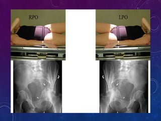
WELCOME TO ALL…..
PELVIS XRAY PROJECTIONS
MISS.JENIFER C,
DRDT 1ST YEAR,
KILPAUK MEDICAL COLLEGE,
CHENNAI-10
PELVIS ANATOMY
 The pelvis is either the lower part of the trunk of the human body between
the abdomen and the thighs.
 It includes several structures : the bony pelvis, the pelvic cavity, the pelvic
floor, and the perineum.
 The pelvic spine consists of the sacrum and coccyx.
 At birth, each pelvic half consists of 3 separate primary bones:
 The Ilium
 The Ischium
 The Pubis
 These bones are joined by hyaline cartilage
TYPES OF HUMAN PELVIS
MALE PELVIS
• Pelvic inlet Heartshaped , narrow
• Obturator foramen Round
• Pubic angle Narrow (< 70°)
FEMALE PELVIS
• Pelvic inlet Oval and rounded; wide
• Obturator foramen Oval
• Pubic angle Wide (> 80°)
MALE FEMALE
PATIENT PREPARATION
Remove all radio
opaque material
BASIC PROJECTIONS OF PELVIS
1) ANTERO-POSTERIOR PROJECTION
2) INLET PROJECTION
3) OUTLET PROJECTION
4) JUDET PROJECTION
5) FLAMINGO PROJECTION
The AP pelvis view is part of a pelvic series examining the
iliac crest, sacrum, proximal femur, pubis, ischium and the
great pelvic ring. It is of considerable importance in the
management of severely injured patients presenting to
emergency departments.
Patient position
 patient is supine
 lower limbs are internally rotated 15-25° from the hip
(do not attempt this if a fracture is suspected)
PELVIS ANTEROPOSTERIOR PROJECTION
Technical factors
AP projection
Centring point
The midpoint of the anterior superior iliac spine and the pubic symphysis
Collimation
Laterally to the skin margins
Superior to above the iliac crests
Inferior to the proximal third of the femur
Orientation
Landscape
Detector size
35 cm x 43 cm
Exposure
70-80 kVp
20-30 mAs
SID
100 cm
Grid
Yes
Image Technical Evaluation
 Entirety of the bony pelvis is imaged from superior of
the iliac crest to the proximal shaft of the femur.
 Obturator foramina appear equal.
 Iliac wings have an equal concavity.
 Greater trochanters of the proximal femur are in profile.
The AP outlet view is part of a pelvic series examining the iliac crest,
sacrum, proximal femur, pubis, ischium and the great pelvic ring. It is
of considerable importance in the management of severely injured
patients presenting to emergency departments. This particular view
allows for assessment of the cephalic/caudal translation and superior
migration of the hemipelvis following trauma.
Patient position
 Patient is supine
 Lower limbs are internally rotated 15-25° from the hip (do not
attempt this if a fracture is suspected)
 Patient hands are out of the way of the imaging field
ANTERO POSTERIOR OUTLET PROJECTION
Technical factors
AP axial projection
Centring point
5 cm distal to the superior pubic symphysis border
The central ray is angled 20-35° cephalic for males and 30-45° for females.
Ensure primary beam is aligned with the image receptor
Collimation
Laterally to the skin margins
Superior to above the iliac crests
Inferior to the proximal femur
Orientation
landscape
Detector Size
35 cm x 43 cm
Exposure
70-80 kVp
20-30 mAs
SID
100 cm
Grid
yes
Image technical evaluation
 The entirety of the bony pelvis is imaged from superior
of the iliac crest to the proximal shaft of the femur.
 The pubic symphysis should be central to the image with
little to no patient rotation.
 There is a clear demonstration of both the anterior and
inferior pubic ramus with little to no foreshortening
The AP inlet view is part of a pelvic series examining the iliac
crest, sacrum, proximal femur, pubis, ischium and the great pelvic ring.
It is of considerable importance in the management of severely injured
patients presenting to emergency departments 1. This particular view is
perpendicular to the pelvic rim, allowing for assessment of any
suspected narrowing or widening of that rim. Additionally it is used to
assess anterior-posterior displacement of pubic rami fractures.
Patient position
 patient is supine
 lower limbs are internally rotated 15-25° from the hip (do not
attempt this if a fracture is suspected)
 patient's hands are out of the way of the imaging field
ANTERO POSTERIOR INLET PROJECTION
ANTERO POSTERIOR INLET
PROJECTION
Technical factors
AP superoinferior projection
Centering point
Midline at the level of the anterior superior iliac spine
The central ray is angled 25-40° caudal to be perpendicular to the plane
Ensure central ray is aligned with the image receptor
Collimation
Laterally to the skin margins
Superior to above the iliac crests
Inferior to the proximal femur
Orientation
Landscape
Detector size
35 cm x 43 cm
Exposure
70-80 kVp
20-30 mAs
SID
100 cm
Grid
Yes
Image technical evaluation
 The entirety of the bony pelvic rim is central to the image
without superimposition
 The iliac wings are evident on the superior portion of the
image, the inferior and superior pubic rami are
superimposed on the inferior portion.
The oblique pelvis otherwise known as the Judet view is an additional
projection to the pelvic series when there is suspicion of an acetabular
fracture.
The Judet view is comprised of two projections, first the iliac oblique
for assessment of the posterior column and anterior wall of the
acetabulum; secondly, the obturator oblique view demonstrating
the anterior column of the pelvis along with the posterior wall of
the acetabulum.
PELVIS JUDET PROJECTION
Patient position
1. Iliac oblique
 patient is supine
 the unaffected side is rotated roughly 45°anterior, generally
aided with a 45° sponge
 it is advisable the patient is central on the table and at no risk
of over rolling
2. Obturator oblique
 patient is supine
 the affected side is rotated roughly 45° anterior, generally
aided with a 45° sponge
 ensure the patient is central on the table and at no risk of over
rolling
Technical factors
Centring point
Iliac oblique
5 cm distal and 5 cm medial of the ASIS closest to the image receptor
Obturator oblique
5 cm distal and 5 cm medial of the ASIS that is rolled up anterior to the image receptor
Collimation
Superior to the level of the ASIS
Inferior to the proximal femur
Laterally to the skin margins
Medially to the pubic symphysis
Orientation
Portrait
Detector size
24 cm x 30 cm
Exposure
70-80 kVp
10-20 mAs
SID
100 cm
Grid
Yes
Image technical evaluation
 The iliac oblique projection should demonstrate the
anterior rim of the acetabulum as well as the posterior
ilioischial column. The iliac wing, as it is 'flatten' out on
the image should be well demonstrated.
 The obturator oblique projection should confidently show
the posterior rim as well as the anterior ilioischial line, as
per the name the obturator foramen is well demonstrated.
The flamingo view series of the pelvis is a specialized
orthopedics series consisting of three separate pelvis
projections. It is used for assessing instability of the pubic
symphysis, often in the context of previous pelvic trauma.
This projection should only be performed under specialist
supervision or referral.
Patient position
The series is comprised of three separate projections
traditionally performed AP erect, however patients with
balance issues can benefit from a PA projection.
PELVIS FLAMINGO PROJECTION
Neutral
 patient is erect with both feet evenly planted on the ground
 standing AP (or PA) with the posterior aspect of the pelvis resting against the
upright detector
 patient's hands are out of the way of the imaging field
Left foot raised
 patient is erect with left foot off the floor for the projection, patient is reminded
to place weight on right foot
 standing AP (or PA) with the posterior aspect of the pelvis resting against the
upright detector
 patient's hands are out of the way of the imaging field
Right Foot Raised
 patient is erect with right foot off the floor for the projection, patient is
reminded to place weight on left foot
 standing AP (or PA) with the posterior aspect of the pelvis resting against the
upright detector
 patient's hands are out of the way of the imaging field
PELVIS FLAMINGO PROJECTION
Technical factors
AP/PA erect dynamic projection
Centering point
The midpoint of the anterior superior iliac spine and the pubic symphysis
Collimation
Laterally to the skin margins
Superior to include the anterior superior iliac spine
Inferior to the proximal third of the femur
Orientation
Landscape
Detector size
35 cm x 43 cm
Exposure
70-80 kVp
20-30 mAs
SID
100-150 cm
Grid
Yes
Image technical evaluation
 Clear annotations indicating what image the projection
is in the series
 Entirety of the superior and inferior pubic rami visulised
 Proximal femur visible
CONCLUSION
YOU CANNOT SEE THE RADIATION….
YOU CANNOT SMELL THE RADIATION…
YOU CANNOT FEEL THE RADIATION…..
THANK YOU….

X-RAY PELVIS PROJECTIONS

  • 1.
  • 2.
    PELVIS XRAY PROJECTIONS MISS.JENIFERC, DRDT 1ST YEAR, KILPAUK MEDICAL COLLEGE, CHENNAI-10
  • 3.
    PELVIS ANATOMY  Thepelvis is either the lower part of the trunk of the human body between the abdomen and the thighs.  It includes several structures : the bony pelvis, the pelvic cavity, the pelvic floor, and the perineum.  The pelvic spine consists of the sacrum and coccyx.  At birth, each pelvic half consists of 3 separate primary bones:  The Ilium  The Ischium  The Pubis  These bones are joined by hyaline cartilage
  • 4.
    TYPES OF HUMANPELVIS MALE PELVIS • Pelvic inlet Heartshaped , narrow • Obturator foramen Round • Pubic angle Narrow (< 70°) FEMALE PELVIS • Pelvic inlet Oval and rounded; wide • Obturator foramen Oval • Pubic angle Wide (> 80°)
  • 5.
  • 6.
    PATIENT PREPARATION Remove allradio opaque material
  • 7.
    BASIC PROJECTIONS OFPELVIS 1) ANTERO-POSTERIOR PROJECTION 2) INLET PROJECTION 3) OUTLET PROJECTION 4) JUDET PROJECTION 5) FLAMINGO PROJECTION
  • 8.
    The AP pelvisview is part of a pelvic series examining the iliac crest, sacrum, proximal femur, pubis, ischium and the great pelvic ring. It is of considerable importance in the management of severely injured patients presenting to emergency departments. Patient position  patient is supine  lower limbs are internally rotated 15-25° from the hip (do not attempt this if a fracture is suspected) PELVIS ANTEROPOSTERIOR PROJECTION
  • 9.
  • 10.
    Technical factors AP projection Centringpoint The midpoint of the anterior superior iliac spine and the pubic symphysis Collimation Laterally to the skin margins Superior to above the iliac crests Inferior to the proximal third of the femur Orientation Landscape Detector size 35 cm x 43 cm Exposure 70-80 kVp 20-30 mAs SID 100 cm Grid Yes
  • 11.
    Image Technical Evaluation Entirety of the bony pelvis is imaged from superior of the iliac crest to the proximal shaft of the femur.  Obturator foramina appear equal.  Iliac wings have an equal concavity.  Greater trochanters of the proximal femur are in profile.
  • 12.
    The AP outletview is part of a pelvic series examining the iliac crest, sacrum, proximal femur, pubis, ischium and the great pelvic ring. It is of considerable importance in the management of severely injured patients presenting to emergency departments. This particular view allows for assessment of the cephalic/caudal translation and superior migration of the hemipelvis following trauma. Patient position  Patient is supine  Lower limbs are internally rotated 15-25° from the hip (do not attempt this if a fracture is suspected)  Patient hands are out of the way of the imaging field ANTERO POSTERIOR OUTLET PROJECTION
  • 13.
  • 14.
    Technical factors AP axialprojection Centring point 5 cm distal to the superior pubic symphysis border The central ray is angled 20-35° cephalic for males and 30-45° for females. Ensure primary beam is aligned with the image receptor Collimation Laterally to the skin margins Superior to above the iliac crests Inferior to the proximal femur Orientation landscape Detector Size 35 cm x 43 cm Exposure 70-80 kVp 20-30 mAs SID 100 cm Grid yes
  • 15.
    Image technical evaluation The entirety of the bony pelvis is imaged from superior of the iliac crest to the proximal shaft of the femur.  The pubic symphysis should be central to the image with little to no patient rotation.  There is a clear demonstration of both the anterior and inferior pubic ramus with little to no foreshortening
  • 16.
    The AP inletview is part of a pelvic series examining the iliac crest, sacrum, proximal femur, pubis, ischium and the great pelvic ring. It is of considerable importance in the management of severely injured patients presenting to emergency departments 1. This particular view is perpendicular to the pelvic rim, allowing for assessment of any suspected narrowing or widening of that rim. Additionally it is used to assess anterior-posterior displacement of pubic rami fractures. Patient position  patient is supine  lower limbs are internally rotated 15-25° from the hip (do not attempt this if a fracture is suspected)  patient's hands are out of the way of the imaging field ANTERO POSTERIOR INLET PROJECTION
  • 17.
  • 18.
    Technical factors AP superoinferiorprojection Centering point Midline at the level of the anterior superior iliac spine The central ray is angled 25-40° caudal to be perpendicular to the plane Ensure central ray is aligned with the image receptor Collimation Laterally to the skin margins Superior to above the iliac crests Inferior to the proximal femur Orientation Landscape Detector size 35 cm x 43 cm Exposure 70-80 kVp 20-30 mAs SID 100 cm Grid Yes
  • 19.
    Image technical evaluation The entirety of the bony pelvic rim is central to the image without superimposition  The iliac wings are evident on the superior portion of the image, the inferior and superior pubic rami are superimposed on the inferior portion.
  • 20.
    The oblique pelvisotherwise known as the Judet view is an additional projection to the pelvic series when there is suspicion of an acetabular fracture. The Judet view is comprised of two projections, first the iliac oblique for assessment of the posterior column and anterior wall of the acetabulum; secondly, the obturator oblique view demonstrating the anterior column of the pelvis along with the posterior wall of the acetabulum. PELVIS JUDET PROJECTION
  • 21.
    Patient position 1. Iliacoblique  patient is supine  the unaffected side is rotated roughly 45°anterior, generally aided with a 45° sponge  it is advisable the patient is central on the table and at no risk of over rolling 2. Obturator oblique  patient is supine  the affected side is rotated roughly 45° anterior, generally aided with a 45° sponge  ensure the patient is central on the table and at no risk of over rolling
  • 23.
    Technical factors Centring point Iliacoblique 5 cm distal and 5 cm medial of the ASIS closest to the image receptor Obturator oblique 5 cm distal and 5 cm medial of the ASIS that is rolled up anterior to the image receptor Collimation Superior to the level of the ASIS Inferior to the proximal femur Laterally to the skin margins Medially to the pubic symphysis Orientation Portrait Detector size 24 cm x 30 cm Exposure 70-80 kVp 10-20 mAs SID 100 cm Grid Yes
  • 24.
    Image technical evaluation The iliac oblique projection should demonstrate the anterior rim of the acetabulum as well as the posterior ilioischial column. The iliac wing, as it is 'flatten' out on the image should be well demonstrated.  The obturator oblique projection should confidently show the posterior rim as well as the anterior ilioischial line, as per the name the obturator foramen is well demonstrated.
  • 25.
    The flamingo viewseries of the pelvis is a specialized orthopedics series consisting of three separate pelvis projections. It is used for assessing instability of the pubic symphysis, often in the context of previous pelvic trauma. This projection should only be performed under specialist supervision or referral. Patient position The series is comprised of three separate projections traditionally performed AP erect, however patients with balance issues can benefit from a PA projection. PELVIS FLAMINGO PROJECTION
  • 26.
    Neutral  patient iserect with both feet evenly planted on the ground  standing AP (or PA) with the posterior aspect of the pelvis resting against the upright detector  patient's hands are out of the way of the imaging field Left foot raised  patient is erect with left foot off the floor for the projection, patient is reminded to place weight on right foot  standing AP (or PA) with the posterior aspect of the pelvis resting against the upright detector  patient's hands are out of the way of the imaging field Right Foot Raised  patient is erect with right foot off the floor for the projection, patient is reminded to place weight on left foot  standing AP (or PA) with the posterior aspect of the pelvis resting against the upright detector  patient's hands are out of the way of the imaging field
  • 27.
  • 28.
    Technical factors AP/PA erectdynamic projection Centering point The midpoint of the anterior superior iliac spine and the pubic symphysis Collimation Laterally to the skin margins Superior to include the anterior superior iliac spine Inferior to the proximal third of the femur Orientation Landscape Detector size 35 cm x 43 cm Exposure 70-80 kVp 20-30 mAs SID 100-150 cm Grid Yes
  • 29.
    Image technical evaluation Clear annotations indicating what image the projection is in the series  Entirety of the superior and inferior pubic rami visulised  Proximal femur visible
  • 30.
    CONCLUSION YOU CANNOT SEETHE RADIATION…. YOU CANNOT SMELL THE RADIATION… YOU CANNOT FEEL THE RADIATION…..
  • 31.