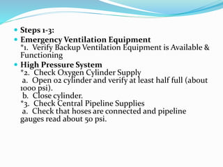
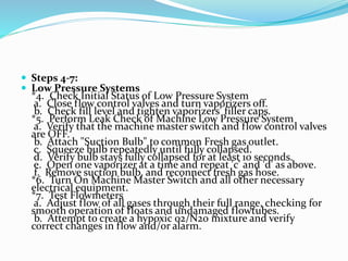
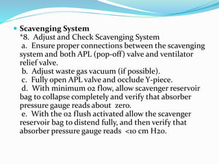
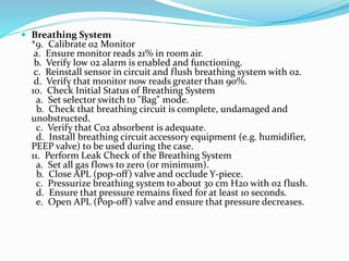
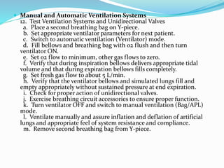
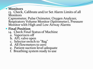
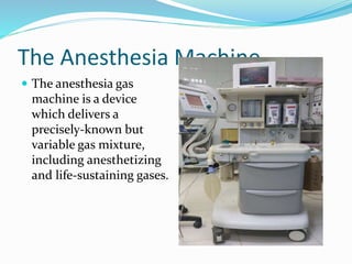
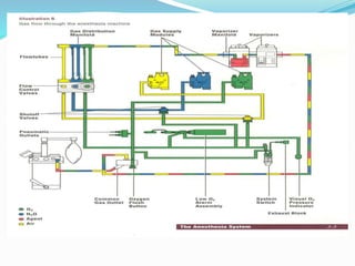
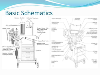
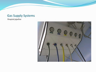
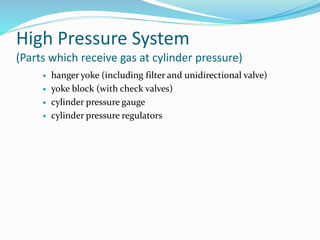
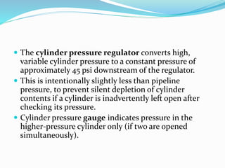
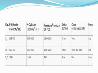
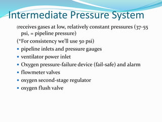
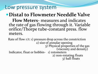
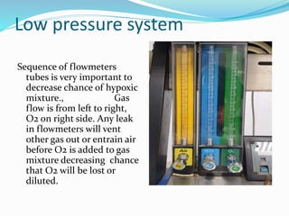
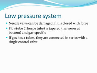
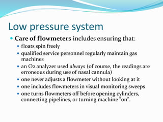
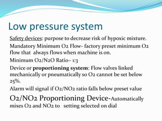
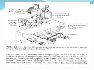
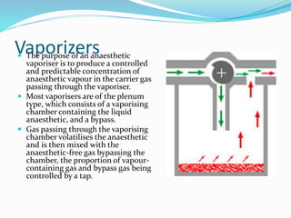
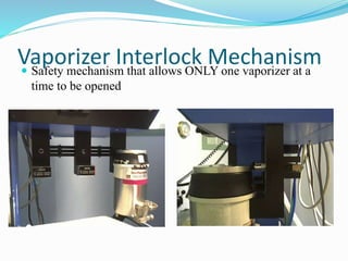
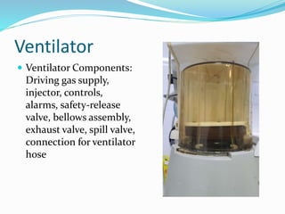
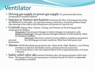
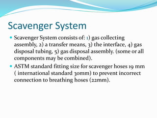
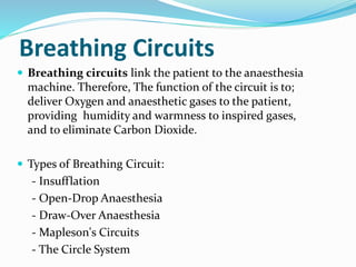
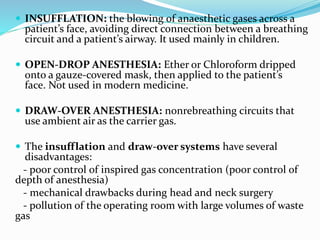
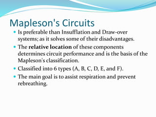
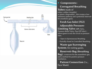
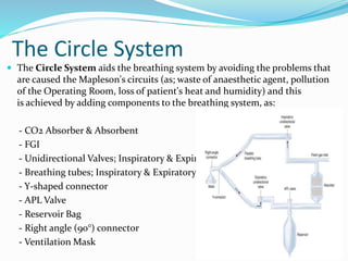
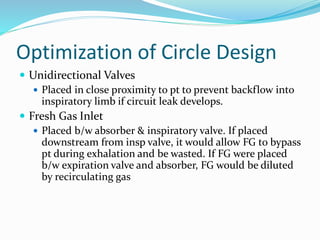
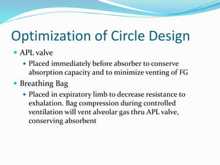
The document provides instructions for checking an anesthesia machine. It outlines 14 steps to check the emergency ventilation equipment, oxygen and gas supplies, low pressure and scavenging systems, breathing circuit, ventilation systems and monitors. Key checks include verifying backup ventilation, oxygen cylinder levels, gas pipeline pressures, checking for leaks in the low pressure and breathing systems, calibrating monitors, and ensuring the final status of the machine is safe. The checkout is recommended before each use to ensure the anesthesia machine is functioning properly and can deliver a safe gas mixture to patients.


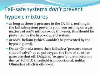
![Fail-safe systems don't prevent hypoxic
mixtures (Cont…)
Ohmeda uses a second-stage O2 pressure regulator
(ensures constant oxygen flowmeter input until supply
pressure is less than 12-16 psi). The oxygen ratio
monitor controller (ORM [newer] or ORMC, both by
Dräger) shuts off nitrous oxide when oxygen pressure
is less than 10 psi](https://image.slidesharecdn.com/myanesthesiamachine-230314124410-7f36f955/85/Anesthesia-Machine-pptx-31-320.jpg)


![ANESTHESIA_MACHINE-_PRESSURE_REDUCING_VALVES,_FLOWMETER_AND[1].pptx](https://cdn.slidesharecdn.com/ss_thumbnails/anesthesiamachine-pressurereducingvalvesflowmeterand1-250127121142-c2585726-thumbnail.jpg?width=640&height=640&fit=bounds)


