Use of Hydrogen in Fiat Lancia Petrol engine, Combustion Process and Determination of Optimum Valve Timing

To our path towards green economy, Hydrogen is often regarded to have a potential growth in the coming future. However, the high cost of operation of fuel cell has often been a setback. If we could make use of hydrogen gas as a fuel directly, the scope of development broadens. Owing to these aspects, this work primarily focuses on the simulation technique of an Internal Combustion Spark Ignition Engine powered by Hydrogen gas. The simulations of various stages have been carried out using the discrete approach, thereby investigating the pressures and temperatures at various instants in the cycle. For the relative performance discussion we have simulated the different cycles as ideal cycle, air fuel cycle and actual cycle. The resultant cyclic graph indicates various discrepancies between ideal, air fuel and actual cycle. This analysis serves as a tool for a better understanding of the variables involved and helps in optimizing engine design and fixing of various parameters, including the determination of valve timings. Besides this, backfire, is the commonly faced problem with the hydrogen engines. To reduce this effect, a fuel injectoris used for adding the gaseous fuel to the combustion chamber.

Recommended
Recommended
More Related Content
What's hot
What's hot (20)
Viewers also liked
Similar to Use of Hydrogen in Fiat Lancia Petrol engine, Combustion Process and Determination of Optimum Valve Timing
Similar to Use of Hydrogen in Fiat Lancia Petrol engine, Combustion Process and Determination of Optimum Valve Timing (20)
More from IOSR Journals
Recently uploaded
Recently uploaded (20)
Use of Hydrogen in Fiat Lancia Petrol engine, Combustion Process and Determination of Optimum Valve Timing
- 1. IOSR Journal of Mechanical and Civil Engineering (IOSR-JMCE) e-ISSN: 2278-1684,p-ISSN: 2320-334X, Volume 9, Issue 4 (Nov. - Dec. 2013), PP 43-49 www.iosrjournals.org www.iosrjournals.org 43 | Page Use of Hydrogen in Fiat Lancia Petrol engine, Combustion Process and Determination of Optimum Valve Timing Harsh Tamakuwala1) Dr. S. A. Channiwala2) 1 (Mechanical Engineering, National Institute of Technology, Surat, India) 1 (Mechanical Engineering,Professor, National Institute of Technology, Surat, India) Abstract: To our path towards green economy, Hydrogen is often regarded to have a potential growth in the coming future. However, the high cost of operation of fuel cell has often been a setback. If we could make use of hydrogen gas as a fuel directly, the scope of development broadens. Owing to these aspects, this work primarily focuses on the simulation technique of an Internal Combustion Spark Ignition Engine powered by Hydrogen gas. The simulations of various stages have been carried out using the discrete approach, thereby investigating the pressures and temperatures at various instants in the cycle. For the relative performance discussion we have simulated the different cycles as ideal cycle, air fuel cycle and actual cycle. The resultant cyclic graph indicates various discrepancies between ideal, air fuel and actual cycle. This analysis serves as a tool for a better understanding of the variables involved and helps in optimizing engine design and fixing of various parameters, including the determination of valve timings. Besides this, backfire, is the commonly faced problem with the hydrogen engines. To reduce this effect, a fuel injectoris used for adding the gaseous fuel to the combustion chamber. Keyword: Actual cycle, air fuel cycle, backfire, discrete approach, fuel injector, fuel cell, hydrogen, ideal cycle, spark plug, valve timings ,Fiat Lancia,inlet valve, exhaust valve, optimum valve timing . I. Introduction An intense research effort is on-going in the field of engines to develop new engines with improved efficiency and decreased harmful emission. Further, to overcome the high dependency of automobiles on the limited crude oil, huge focus is laid on the development of engines that are powered by alternate fuels, which can even reduce the rate of pollution in the world that is currently being done by the hydrocarbons. Amongst all, hydrogen, a fuel that powers the sun, is looking forward to run our vehicles too. The merits of using it as a fuel are immense, few of which includes it production from renewable energy sources, a better efficiency over petrol and harmless exhaust gases, mostly water vapour. To study different engines, computer based thermodynamic models have been developed which can predict the performance, avoiding the difficulties associated with the detailed experimental analysis.Simulation of ideal cycle involves much less complexities since the initial conditions are known. But it is quite clear that an ideal cycle cannot predict the exact conditions that an engine will face during its working period. An actual model incorporates equations,which need to be solved using the method of iterations. Two approaches can be followed for simulation of an IC engine- (i) The Differential Approach (ii) The Discrete Method. The first method involves solving of partial differential equations based on energy, mass and momentum conservation (1). The later model considers the calculations at each degree of crank rotation (or smaller) considering a few assumptions at the initial stage but by iterating, ultimately reaching the exactconditions inside the combustion chamber. This later approach is followed in this work and calculations are made which are discussed later in the section of tables. The graphical charts plotted later, provides a comparison of the actual cycle with the ideal and air fuel cycle. Throughout this present work, a single cylinder, four stroke spark ignition engine, with a hydrogen fuel injector, is used to illustrate all of the thermodynamic points to be made. The engine has a bore (B) of 73 mm diameter, stroke length(L) of 70 mm, flywheel of radius (r) 35 mm and connecting rod of length (l) 170 mm. Further the values presented here are for engine running at 1000 rpm. The compression ratio taken is 7.96 with a clearance volume of 4.2023 x 10⁻⁵ m3 . The variations of specific heats, enthalpy and equilibrium constants of different gases with temperature were obtained based on relationships established from JANAF tables. II. Mathematical Models The simulations of any engine is done and compared with the results of ideal cycle to get a clear idea of the cycle.
- 2. Use of Hydrogen in Petrol engine, Combustion Process and Determination of Optimum Valve Timing www.iosrjournals.org 44 | Page 2.1The Ideal Cycle&Air-fuel cycle The ideal cycle serves as a standard for comparison of operations of various cycles. In ideal cycle we have taken air as a working medium and a few standard assumptions for obtaining maximum achievable efficiency. Furthermore, by considering air-fuel cycle, we move a step closer towards actual analysis, since most variations as a function of temperature are taken into consideration into this calculation, expect for the friction and convective heat losses. Also the process of suction and exhaust is not taken into account in these two cycles. The unknown value of temperature (T) at different crank angles is calculated using below equation obtained by integrating the equation for entropy balance utilized only for air fuel analysis. 1 0 0 0 ln ln .... 1 V T R a b T t V t vwhere C a bT 2.2The Discrete Approachfor Actual Cycle In the present simulations, the governing parameters of the engine- pressure, temperature, volume and mass are calculated at each degree of crank rotation. In an actual cycle, the remains of exhaust gases have to be considered for simulation of suction process. However, the quantity of remaining exhaust gases and its temperature and pressure can be known only after the whole cycle is simulated. Hence here initially these parameters are assumed to simulate the processes of suction, compression, combustion, expansion and exhaust. The parameters obtained after exhaust are taken to iterate the cycle again. The detailed method of simulation of these processes is discussed in the following topics. Assumptions: In this work, the gas mixture has been considered as an ideal gas. Also, the losses in inlet and exhaust manifold are not considered. In combustion chamber the gases have been considered to have uniform temperature.Pre-ignition has not been considered and the combustion is considered to be occurring at constant volume.The wall temperature (Twall),convective heat transfer coefficient (H) and friction loss (Fq) is calculated using the following equations. 0.388 423 ... 2wallT K 1 07 2 2 2 8.5 10 ... 3 2 q mean T TBL F V v 0.2 0.8 0.55 0.8 1 10.013 ... 4 meanH B P T V 2.2.1 Suction The calculation of the process of suction begins with the assumption that the temperature remains constant during the specific degree of crank rotation. Based on this and assuming the values of mass, temperature and pressure of the exhaust gases we calculate the different parameters using the below mentioned equations. 0 0 1 1 ... 5 PV P V 1 .... 6atmP P P 1 2 ... 7d P velocity u C Where ρ is densitycalculated taking into consideration mass leaving or fresh air entering depending on the pressure difference. 1 ... 8 m Au t 1 0 .... 9mass m m m The calculations for mass fraction and gas constant are also done at the particular instant. Further, using the values of calculated mass, mass fraction and taking specific heats of each constituent as a function of temperature, obtained from JANAF Tables, We have than calculated the value of temperature by solving quadratic equation obtained by the energy conservation in flow process using the equation below, since its value changes due to exchange of mass.
- 3. Use of Hydrogen in Petrol engine, Combustion Process and Determination of Optimum Valve Timing www.iosrjournals.org 45 | Page 1 0 1 0 0 0 1 0 ; 0 2 ... 10 ; 0 o air p p new o p p new o p p air C T C T m C T m m mC T m C T mC T m Using the momentum and energy conservation law, the modified temperature can be calculated considering the losses occurring in friction and convection (q)which further can be used to find out modified pressure. These new values are used to iterate the suction process from the start. Generally, 2-3 iterations give a good level of accurate values. 2.2.2Compression 2.2.2.1 Compression prior to injection After the suction stroke, the calculations of compression begin by assuming adiabatic process and hence calculating the temperature T1 after each 10 rotation throughout the stroke. 1 1 .... 11d dT V T V The losses in compression follow same approach as in suction, thereby giving variation in temperature. Further,the new value of γ is calculated at an average temperature of corrected and initialones. Then using this value of γ we do good number of iterations to get the exact temperature. Pressure at this corrected temperature can be obtained easily by, .... 12d d d P V P V T T 2.2.2.2 Fuel injection Fuel injector is opened at a specific degree of crank rotation during compression and the process follows the one followed during suction. It has been started at 2800 and kept open till the required particular mass entersconsidering pre-ignition and turbulence factors. Inlet temperature of fuel is 300K. 2.2.2.3 Compression post injection After the injection of fuel the same process of compression is followed again, once the fuel injector is shut off. 2.2.3 Combustion The simulation of combustion involves complexities of solving seven equations to obtain moles of six products and the temperature after combustion. To solve these equations, the method of iteration has been used. These equations can be obtained as: The combustion equation yields three equations by mole comparison of H, O and N, where the reactant parameters-the temperature, pressure, moles and mass can be knownfromcompression stroke. 2 2 2 2 2 2 2 xH + yO + y'N aO +bN +cH + dH O+eOH+fNO 2 2 2 .... 13 2 ' 2b f ... 14 2 2 .... 15 x c d e y y a d e f The equilibrium constants can be expressed in terms of partial pressure as: 2 2 2 2 2 2 2 2 2 1 22 2 1 ... 16 ... 17 ... 18 H O OH H o H o NO N o P P k k P P P P P k P P Finally the energy balance on the reactant and product sides gives .... 19p j j r i i p r H n RT H n RT Thus, to solve these 7 equations, initially we can suppose a temperature and find out the values of the constants in equation (13) - (18). The values of x and y are determined from the mass and moles fractions. Then the obtained values are verified using equation (19). After multiple iterations, we have obtained the moles of the products and the temperature which can be used to find pressure by ideal gas equation.
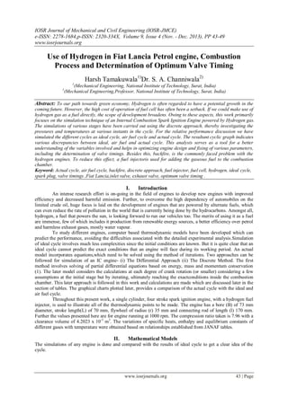
- 4. Use of Hydrogen in Petrol engine, Combustion Process and Determination of Optimum Valve Timing www.iosrjournals.org 46 | Page 0 0.0002 0.0004 0.0006 0 100 200 300 ExhaustValveArea (m2) θ 2.2.4 Expansion and Exhaust The simulation of expansion, after combustion, follows the same approach as done in the compression stroke 3.2.2. Similarly, using the equations and method of suction 3.2.1, we can simulate the exhaust to obtain the final pressure and temperature. This final temperature and pressure is used as initial data for suction to iterate the whole cycle repeatedly, until sufficient accuracy in values of these parameters are not obtained. 2.2.5 Area Planar of the inlet-exhaust openings Since the analysis is based onFiat Lanciaengine, in this work, for our simulation, we have taken the area of the openings of the valve, keeping the ascent and descent angle of both the valves as designed. Also the variations in the valve lift and area of opening of the valves has been taken as designed which is presented in the graph below. However due to large area of the opening the exhaust blow-down loss is high. Hence various simulations are run for different areas and finally reduced the area by 75% of the practical valves for appropriate suction and compression. 2.2.6 Determination of valve timings We analyzed different valve timings to fix an optimum value giving maximum efficiency. But the inlet and exhaust valve advance are mutually dependent. However, the changing in work done by the engine varies quite less with inlet advance, since the pressure during the inlet valve opening is quite less as compared to the exhaust valve opening, as observed from the table (3). We have, hence, initially fixed the inlet valve advance as 100 before TDC, as referred from V. Ganesan [3], to thereby determine the accurate valve timings for the exhaust valve. Now, using the previously fixed timings, we can finally obtain the same for the inlet valve considering maximum mass entry of Oxygen. The parameters for different valve timings have been noted in the table (6). According to the data of the engine valves, the inlet valve is kept open for 2100 and exhaust valve for 2400 of crank angle. III. Simulation results Table (a). Variations in Exhaust valve timings Exhaust Advance (Before BDC) Work Done (J) Efficiency (%) 40 483.95 39.506 35 484.379 39.541 30 499.18 40.75 25 483.915 39.503 20 482.905 39.42 Table (b). Variations in inlet valve timings InletAdvance (Before TDC) Amount of Oxygen entering (kg) (x 10e-4) 22 0.7978 16 0.8146 15 0.81476 14 0.8136 10 0.78677 0 0.0002 0.0004 0.0006 0 100 200 300 InletValveArea (m2) θ Figure 1: Inlet Valve Area vs θ Figure 2: Inlet Valve Area vs θ
- 5. Use of Hydrogen in Petrol engine, Combustion Process and Determination of Optimum Valve Timing www.iosrjournals.org 47 | Page Table 1.Suction Theta Volume (m3) (10e-5) Temperature (K) Pressure N/m2 (10e5) 1 42.050 510.1035 0.9934 2 42.130 511.1578 1.0264 180 33.4851 325.2976 0.9871 194 33.1433 325.2099 1.0020 195 33.0925 325.2101 1.0034 Table 2.Compression Theta Volume (m3 ) (10-5 ) Temperature (K) Pressure (10e5) 196 33.038 325.2066 1.0034 280 17.815 411.3374 2.32356 Mass before Injection 3.5622 x 10⁻⁴ 281 17.555 408.1219 2.4166 283 17.033 402.215 2.6071 285 16.512 396.9172 2.8089 287 15.992 392.1395 3.0233 289 15.475 387.8091 3.2511 291 14.960 383.8663 3.4937 Mass After Fuel is Injected 3.6496 x 10⁻⁴ 360 4.2024 622.6619 20.504 *** = Fuel Injector is kept open Table 3. After Combustion Parameters Compound Variables Moles O2 a 2.3966 x 10⁻⁸ N2 b 0.0095 H2 c 4.921 x 10⁻¹⁰ H2O d 0.0050 OH e 3.9899 x 10⁻⁹ NO f 4.32 x 10⁻⁵ Pressure 89.54 Temperature 3131 Table 4.Expansion Theta Volume (m3 ) (10e-5) Temperature (K) Pressure N/m2 (10e5) 361 4.2041 3130.674 89.49586 509 31.7668 1865.216 7.066 510 31.8742 1863.46 7.035 Table 5. Exhaust Theta Volume (m3) (10e- 4) Temperature (K) Pressure N/m2 (10e5) 511 31.9780 1863.46 7.035 715 4.2795 713.1197 0.979 716 4.2534 663.1463 0.9828 719 4.2073 550.5722 0.9911 720 4.2026 521.9448 0.9934
- 6. Use of Hydrogen in Petrol engine, Combustion Process and Determination of Optimum Valve Timing www.iosrjournals.org 48 | Page IV. Graphs
- 7. Use of Hydrogen in Petrol engine, Combustion Process and Determination of Optimum Valve Timing www.iosrjournals.org 49 | Page V. Interpretation The dependency of efficiency is quite low on inlet advance, compared to exhaust advance since the pressure is quite high at exhaust opening in contrast to the instant at inlet advance angle. By calculating efficiencies for various exhaust angle advance, maximum efficiency is found to be occurring at 5100 , resulting in optimized piston work against high cylinder pressure and loss of expansion stroke and is closed at 100 after TDC. At 1000 rpm and Ф=1, we selected -150 and 1950 of crank rotation for opening and closing of inlet valve to permit the maximum entry of O2 gas in enginesince inlet valve is designed to be kept open for 2100 . During the crank rotation angle of 2810 -2910 , there is rapid increase in pressure because of injected hydrogen in combustion chamber. For equivalence ratio equal to 1 the mass entry required is 8.74 x 10⁻⁶ kg and hence the fuel injector is kept open for 100 of crank rotation. At equivalence ratio 1, combustion of 1g of H2 produces 0.13334 g of NO and hence the %NO emission is 0.391% which is very less considering NO to be a dangerous emission. The work done in the actual cycle is 499.18 J/cycle and hence the efficiency of the cycle is 40.75% and the efficiency of ideal cycle is 56.25 % VI. Conclusions From the results of simulation, we obtained the efficiency of actual cycle 40.75% which is 72.39% of the ideal cycle when Exhaust valve advance is 300 and closes 100 after TDC. Inlet valve advance is 150 before TDC and closes at 195c of crank rotation.We have seen that the emission percentage of NO has been very less and here there is no emission of CO2 orCO and hence it is environment friendly. References [1] Books: Heywood J., Internal Combustion Engine Fundamentals, 1st Edition, Tata McGraw-Hill,USA, 1988, chap. 9-10. [2] Book: V. Ganesan, Internal Combustion engines. [3] Murat CINIVIZ, Hydrogen use in internal combustion engine:A Review Mechanical engineering department, Selcuk University, Konya Turkey, 21011 [4] http://kinetics.nisd.gov/janaf [5] Vikas Patel., Analysis of Hydrogen engine by differential and discrete approach, Ph.D Thesis, S. V. N.I.T, Surat, 2006 [6] Jose J Granda, Karl Sime, Computer Aided Modelling of Four Stroke Internal combustion engine, California State University, Sacramento [7] http://www.engr.colostate.edu [8] J.M.Gones Antunes, R Mikalsen, A. P. Roskilly, An experimental study of a direct injection compression ignition hydrogen engine, Sir Joseph Institute for Energy Research, Newcastle University, England U.K. [9] Probir Kumar Bose, Rahul Banerjee, and Madhujit Deb, Hydrogen and Diesel Combustion on a Single Cylinder Four Stroke Diesel Engine in Dual FuelMode with Varying Injection Strategies [10] VVN BHASKAR, Dr. R. HARI PRAKASH, Dr. B. DURGA PRASAD, HYDROGEN FUELLED IC ENGINE – ANOVERVIEW [11] “Simulation of Compression Ignition Engine Processes with Jatropha Bio-Diesel”, Presented & Published in the proceedings ofInternational Conf.on Bio-Fuels, Vision-2015, Oct. 13-15, 2006, Engg. College Bikaner, India. [12] B.Rajendra Prasath, E.Leelakrishnan, N. Lokesh, H. Suriyan, E. Guru Prakash, K. Omur Mustaq Ahmed Hydrogen Operated Internal Combustion Engines –ANew Generation Fuel Department of Automobile Engineering, Sriram Engineering College, Anna University Chennai, India.