![R.S. Mishra et al/ International journal of research in engineering and innovation (IJREI), vol 1, issue 2 (2017), 40-48
41
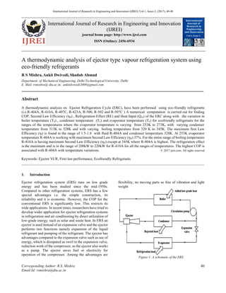
The inter-relation between the different parts can be
expressed by the fig. 1. Boiler used low grade energy to
produce vapours to be expanded inside the ejector. Without
a compressor can this system perform saving high grade
energy and cost.
1.1 Literature Review
Tischendorf et. al. [1] focused on the differences in energy
dissipation in each component compared to the the whole
ejector refrigeration cycle. With help of this analysis,
improvement of energetic efficiency by using an ejector
was set in relation to the potential improvement in
efficiency of other components such as heat exchangers.
The refrigerants R134a and R744 (CO2) were compared in
regard to the entropy production of the heat pump system.
Kshirsagar et. al [2] proposed a combined vapour
compression-ejector refrigeration system which used the
waste heat of condenser of simple vapour compression
system and this heat was utilized to drive the binary ejector
refrigeration system. Cooling effect produced by this
binary system considered as input to the cooling effect of
basic vapour compression system. They also investigated
the characteristics and the efficient design of the ejector to
improve ejector refrigeration systems. The computational
fluid dynamics (CFD) code, FLUENT, was employed to
predict the flow phenomena and performance of CPM and
CMA steam ejectors.
M. M. Rashidi et. al. [3] studied a combined power and
refrigeration cycle that combined the Rankine cycle and
the ejector refrigeration cycle and a solar energy heat
source was used. This combined cycle produced both
power output and refrigeration output simultaneously. The
effects of the evaporator temperature, turbine inlet and
outlet pressures on the thermal and the exergetic
efficiencies were investigated. Simulation results showed
that thermal and exergy efficiencies increase with
increasing evaporator temperature. In addition, it was
found that the increase in the turbine inlet and outlet
pressure leads to the increase in the first law efficiency and
reduction in the second law efficiency.
B. J. Huang et. al. [4] developed a high-performance solar
ejector cooling system using R141b as the working fluid.
Experimentally a COP of 0.5 for a single-stage ejector was
obtained for a cooling system at a generating temperature
of 90°C, condensing temperature of 28°C, and an
evaporating temperature 8°C. For solar cooling
application, an optimum overall COP obtained was around
0.22 at a generating temperature of 95°C, evaporating
temperature of 8°C and solar radiation at 700 Wm .
R.Khajuria et. al. [5] investigated the performance
analysis of ejector refrigeration system with R404A. The
ejector refrigeration system used exhaust emission of
automobile as thermal energy for providing heat to
generator. The result showed that system using R404A as
refrigerant can be used in the ejector refrigeration system
for area ratio 7.84. Also Cooling capacity of the system
increases with increase in evaporator temperature and
generator temperature.
J.Yu et. al. [6] proposed a new ejector refrigeration system
(NERS) with an additional liquid–vapor jet pump. The jet
pump decreased the backpressure of the ejector, and the
entrainment ratio and the coefficient of performance (COP)
was increased for NERS. Two refrigerants namely R134a
and R152a were considered. Calculations showed that
COP of NERS could be improved more effectively and that
happened at the cost of more pump work. The exergy of
the new system was higher.
Kashyap et. al. [7] developed a dimensional mathematical
model to analyse the performance ejector refrigeration
cycle with working fluid R410a and compared with
performance of R134a. The result showed that
performance of R134a was better than R410a for area ratio
5.64 and 7.84.
Jain A. et. al [8] used solar cooling with the help of an
ejector refrigeration system and did mainly two analysis in
this system. By doing the analysis, the result were shown
for the refrigerants under the steady state conditions. Z
Huifan et. al. [9] designed an experimental solar ejector
refrigeration setup using R-134a as working fluid. The
average daily COP was found to be 0.18, and the average
EER was up to 3.5.
There is a huge scope of studying different eco-friendly
refrigerants that can be used as the main working fluid in
the ERS. Different combinations of temperatures can be
observed in the cycle and for all the refrigerants. Variations
of the performance parameters against the temperature can
be obtained by the software simulations. The second law
efficiency is a measure of exergy destroyed during the
cycle. Different working fluids can be compared on that
basis too. An optimum combination of parameters should
be there for the best performance. After such analysis one
can think of modifying the system and enhance its capacity
to utilize the exergy available more efficiently.
Irreversibility can be reduced by using intra-cycle heat
transfer equipment so that the heat lost will be reduced by
this method.
1.2 Ejector Refrigeration System
The system can be inferred to fig.1 which has namely a
condenser, boiler, evaporator, ejector, flash chamber
(between evaporator and ejector), pumps and throttle
valves.](data:image/gif;base64,R0lGODlhAQABAIAAAAAAAP///yH5BAEAAAAALAAAAAABAAEAAAIBRAA7)
Recommended
Recommended
More Related Content
What's hot
What's hot (20)
Similar to Thermodynamic analysis of ejector VCR using eco-friendly refrigerants
Similar to Thermodynamic analysis of ejector VCR using eco-friendly refrigerants (20)
More from Husain Mehdi
More from Husain Mehdi (7)
Recently uploaded
Recently uploaded (20)
Thermodynamic analysis of ejector VCR using eco-friendly refrigerants
- 1. International Journal of Research in Engineering and Innovation (IJREI) Vol-1, Issue-2, (2017), 40-48 ____________________________________________________________________________________________________________________________ International Journal of Research in Engineering and Innovation (IJREI) journal home page: http://www.ijrei.com ISSN (Online): 2456-6934 ___________________________________________________________________________________ Corresponding Author: R.S. Mishra 40 Email Id: rsmishra@dtu.ac.in A thermodynamic analysis of ejector type vapour refrigeration system using eco-friendly refrigerants R S Mishra, Ankit Dwivedi, Shadab Ahmad Department. of Mechanical Engineering, Delhi Technological University, Delhi E. Mail. rsmishra@ dtu.ac.in, ankitdwivedi2008@gmail.com __________________________________________________________________________________ Abstract A thermodynamic analysis on Ejector Refrigeration Cycle (ERC), have been performed using eco-friendly refrigerants (i.e.R-404A, R-410A, R-407C, R-423A, R-500, R-502 and R-507C ) A numerical computation is carried out for finding COP, Second Law Efficiency (ηII) , Refrigeration Effect (RE) and Heat Input (Qin) of the ERC along with the variation in boiler temperature (Tb) , condenser temperature (Tc) and evaporator temperature (Te) for ecofriendly refrigerants for the ranges of the temperatures where the evaporator temperature is varying from 253K to 273K, with varying condenser temperature from 313K to 328K and with varying boiling temperature from 320 K to 345K. The maximum first Law Efficiency (ηI) is found in the range of 1.5-1.8 with fluid R-404A and condenser temperature 328K. At 253K evaporator temperature R-404A is working with maximum Second Law Efficiency (ηII) 37%. For the entire range of boiling temperature R-410A is having maximum Second Law Efficiency (ηII) except at 345K where R-404A is highest. The refrigeration effect is the maximum and is in the range of 200kW to 220kW for R-410A for all the ranges of temperatures. The highest COP is associated with R-404A with temperature variations. © 2017 ijrei.com. All rights reserved Keywords: Ejector VCR, First law performance, Ecofriendly Refrigerants ___________________________________________________________________________________________________ 1. Introduction Ejector refrigeration system (ERS) runs on low grade energy and has been studied since the mid-1950s. Compared to other refrigeration systems, ERS has a few special advantages i.e. the simple construction, its reliability and it is economic. However, the COP for the conventional ERS is significantly low. This restricts its wide applications. In recent times, researchers have tried to develop wider application for ejector refrigeration systems in refrigeration and air conditioning by direct utilization of low-grade energy, such as solar and waste heat. In ERS an ejector is used instead of an expansion valve and the ejector performs two functions namely expansion of the liquid refrigerant and pumping of the refrigerant. The ejector has advantages compared to the expansion valve such as use of energy, which is dissipated as swirl in the expansion valve, reduction work of the compressor, as the ejector also works as a pump. The ejector saves fuel or electricity for operation of the compressor. Among the advantages are flexibility, no moving parts so free of vibration and light weight Figure 1: A schematic of the ERS.
- 2. R.S. Mishra et al/ International journal of research in engineering and innovation (IJREI), vol 1, issue 2 (2017), 40-48 41 The inter-relation between the different parts can be expressed by the fig. 1. Boiler used low grade energy to produce vapours to be expanded inside the ejector. Without a compressor can this system perform saving high grade energy and cost. 1.1 Literature Review Tischendorf et. al. [1] focused on the differences in energy dissipation in each component compared to the the whole ejector refrigeration cycle. With help of this analysis, improvement of energetic efficiency by using an ejector was set in relation to the potential improvement in efficiency of other components such as heat exchangers. The refrigerants R134a and R744 (CO2) were compared in regard to the entropy production of the heat pump system. Kshirsagar et. al [2] proposed a combined vapour compression-ejector refrigeration system which used the waste heat of condenser of simple vapour compression system and this heat was utilized to drive the binary ejector refrigeration system. Cooling effect produced by this binary system considered as input to the cooling effect of basic vapour compression system. They also investigated the characteristics and the efficient design of the ejector to improve ejector refrigeration systems. The computational fluid dynamics (CFD) code, FLUENT, was employed to predict the flow phenomena and performance of CPM and CMA steam ejectors. M. M. Rashidi et. al. [3] studied a combined power and refrigeration cycle that combined the Rankine cycle and the ejector refrigeration cycle and a solar energy heat source was used. This combined cycle produced both power output and refrigeration output simultaneously. The effects of the evaporator temperature, turbine inlet and outlet pressures on the thermal and the exergetic efficiencies were investigated. Simulation results showed that thermal and exergy efficiencies increase with increasing evaporator temperature. In addition, it was found that the increase in the turbine inlet and outlet pressure leads to the increase in the first law efficiency and reduction in the second law efficiency. B. J. Huang et. al. [4] developed a high-performance solar ejector cooling system using R141b as the working fluid. Experimentally a COP of 0.5 for a single-stage ejector was obtained for a cooling system at a generating temperature of 90°C, condensing temperature of 28°C, and an evaporating temperature 8°C. For solar cooling application, an optimum overall COP obtained was around 0.22 at a generating temperature of 95°C, evaporating temperature of 8°C and solar radiation at 700 Wm . R.Khajuria et. al. [5] investigated the performance analysis of ejector refrigeration system with R404A. The ejector refrigeration system used exhaust emission of automobile as thermal energy for providing heat to generator. The result showed that system using R404A as refrigerant can be used in the ejector refrigeration system for area ratio 7.84. Also Cooling capacity of the system increases with increase in evaporator temperature and generator temperature. J.Yu et. al. [6] proposed a new ejector refrigeration system (NERS) with an additional liquid–vapor jet pump. The jet pump decreased the backpressure of the ejector, and the entrainment ratio and the coefficient of performance (COP) was increased for NERS. Two refrigerants namely R134a and R152a were considered. Calculations showed that COP of NERS could be improved more effectively and that happened at the cost of more pump work. The exergy of the new system was higher. Kashyap et. al. [7] developed a dimensional mathematical model to analyse the performance ejector refrigeration cycle with working fluid R410a and compared with performance of R134a. The result showed that performance of R134a was better than R410a for area ratio 5.64 and 7.84. Jain A. et. al [8] used solar cooling with the help of an ejector refrigeration system and did mainly two analysis in this system. By doing the analysis, the result were shown for the refrigerants under the steady state conditions. Z Huifan et. al. [9] designed an experimental solar ejector refrigeration setup using R-134a as working fluid. The average daily COP was found to be 0.18, and the average EER was up to 3.5. There is a huge scope of studying different eco-friendly refrigerants that can be used as the main working fluid in the ERS. Different combinations of temperatures can be observed in the cycle and for all the refrigerants. Variations of the performance parameters against the temperature can be obtained by the software simulations. The second law efficiency is a measure of exergy destroyed during the cycle. Different working fluids can be compared on that basis too. An optimum combination of parameters should be there for the best performance. After such analysis one can think of modifying the system and enhance its capacity to utilize the exergy available more efficiently. Irreversibility can be reduced by using intra-cycle heat transfer equipment so that the heat lost will be reduced by this method. 1.2 Ejector Refrigeration System The system can be inferred to fig.1 which has namely a condenser, boiler, evaporator, ejector, flash chamber (between evaporator and ejector), pumps and throttle valves.
- 3. R.S. Mishra et al/ International journal of research in engineering and innovation (IJREI), vol 1, issue 2 (2017), 40-48 42 Figure 2: Schematic of a typical two-phase ejector design [10] A typical ejector consists of a motive nozzle, a suction chamber, a mixing section, and a diffuser as shown in the fig 2. The ejector converts the internal energy and pressure of the motive fluid stream into kinetic energy. The motive nozzle is of a converging-diverging design allowing the jet exiting the nozzle to become supersonic. Depending on the state of the primary fluid, the flow at the exit of the motive nozzle might be two-phase. Flashing of the primary flow inside the nozzle might get delayed due to thermodynamic and hydrodynamic non-equilibrium effects. Figure 3: the schematic of the ERS High pressure refrigerant vapour is supplied to the nozzle from the boiler and it is expanded in the ejector. Here, the vapour originated from the evaporator is entrained with the high velocity jet and it is further compressed in the thermo- compressor. Now the kinetic energy of the mixture is converted into static pressure and mass is discharged to the condenser. The condensate refrigerant is returned to the boiler to be re-circulated. Here RE is the refrigeration effect, QIn is the heat input to the boiler and QC is the heat rejected in condenser.
- 4. R.S. Mishra et al/ International journal of research in engineering and innovation (IJREI), vol 1, issue 2 (2017), 40-48 43 2. Results & Discussions As mentioned earlier the variation of performance parameters such as COP, Second Law Efficiency (ηII), Refrigeration Effect (RE) and Heat Input (Qin) are studied with the operating temperatures in the boiler, the condenser and the evaporator through a computer simulation. The plots showing the results are as follows. Fig 4 shows that for the same range of boiling temperature R-423A and R- 500 show a decline in the COP with the increase in Tb. The COP obtained for these refrigerants is also less than 1 for most of the range, whereas R-407C is showing a flat result for COP near 1. R502 and R507A show a more or less flat variation from 1.2 to 1.4. For the most of the temperature range R410A is giving highest COP from 1.4 to 1.8. Figure 4: Variation of first law efficiency (COP) with boiler temperature (Tb) The refrigeration effect in fig 5 is showing similar variations as the COP. except the RE for R410A is far more than the rest of the refrigerants in the analysis for the entire range. Figure 5: Variation of Refrigeration effect (RE) with boiling temperature (Tb)
- 5. R.S. Mishra et al/ International journal of research in engineering and innovation (IJREI), vol 1, issue 2 (2017), 40-48 44 Figure 6: Variation of Second (Exergetic efficiency) with boiler temperature (Tb) It can be interpreted from the fig 6 that based on the exergy loss R410A is performing the best where the second law efficiency varies from 20% to 26%. Rest of the refrigerants show similar variation as they show with COP. Figure 7: Variation of heat supplied to the boiler with boiler temperature (Tb) The boiling temperature variation shows the least heat input required. For R502 the average heat input required is of a range of 100kW. Both R507A and R404A shows the similar starting heat input at 320K while for R404A it reduces quickly near 345K. From the fig 8 we can study the variation of COP with TC. Most of the refrigerants are showing a flat variation for the entire operating range. R423A provides the least COP given as .65 to .75 and R404A has the maximum in the range of 1.8 to 2.5. R410A has the next best performance with 1.45 to 1.75 throughout the condenser operation
- 6. R.S. Mishra et al/ International journal of research in engineering and innovation (IJREI), vol 1, issue 2 (2017), 40-48 45 . Figure 8: Variation of first Law Efficiency (COP ) with Condenser operating temperatures. (Tc) Fig 9 shows the requirement of heat input for the boiler for the chosen refrigerants. The heat input is low grade energy and instead of the high grade work it is used. So we get numerous options to arrange sources of for heat. Waste heat from several power generating cycles can be used as the source. The higher is the heat input the lower will be the COP of the cycle, so shows the fig 9 that the least heat input required is for R404A, for which with increase in the operating temperature of the condenser, the heat required is as low as 75kW. Although the trend is decreasing for all the working fluids. Figure 9: Variation of heat input required with Condenser temperatures.(Tc)
- 7. R.S. Mishra et al/ International journal of research in engineering and innovation (IJREI), vol 1, issue 2 (2017), 40-48 46 Figure 10: Variation of Exergetic efficiency with Condenser temperatures (Tc) Through fig 10 we can observe that R404A gives the best exergetic performance with the efficiency ranging from 25% to as high as 45%. Next best option is R410A with the maximum efficiency 30%. It can be seen that R502 and R507A are having results very close and similarly R500 and R407C are very close so these are replaceable fluids for the cycle. The evaporator temperature shows the required temperature to be developed. Here a 20K variation of operating temperature has been taken. The minimum temperature that has been chosen is -20°C and the COP variations for the refrigerants are given in the fig 11. At 253K it can be seen that R404A has a considerably high COP of 1.443 and at 273K it has 1.843. Over the entire range of temperature R410 has a flat range of COP as 1.3 to 1.4 Figure 11: Variation of first Law Efficiency (COP) with evaporator temperatures (Te )
- 8. R.S. Mishra et al/ International journal of research in engineering and innovation (IJREI), vol 1, issue 2 (2017), 40-48 47 The refrigeration effect is the highest for R410A which is 180kW at 253K to 210kW at 273K. Despite a better COP, R404A doesn’t provide a greater RE. R500 and R407C are almost overlapping similarly R502 and R507A. Figure 12: Variation refrigeration effect with evaporator temperatures (Te ) In fig 13 a variation for second law efficiency is shown. It can be seen that as the temperature increases in the evaporator exergy losses increase and the second law efficiency decreases. At 253K the efficiency is the best and it is of range of 38% for R404A and for R410A the efficiency is of a range of 34%. Figure 13: Variation of Exergetic efficiency with evaporator temperatures.
- 9. R.S. Mishra et al/ International journal of research in engineering and innovation (IJREI), vol 1, issue 2 (2017), 40-48 48 3. Conclusions The Numerical computation is carried out for variations of the performance parameters with the operating temperatures in the system. The following conclusions have been drawn. For the variations in the boiling temperature R410A has the best COP ranging from 1.4 to 1.8, also R410A has the best RE. The R410 has a exergetic efficiency ranging in 20% to 26% when the boiling temperature is ranging from 320K to 345K. R502 has the least heat input required for the operation of the cycle. R404A has the maximum in the range of 1.8 to 2.5 when condenser temperature is observed to be from 313K to 328K. With the view of operation of condenser its R404A that requires least heat input for operation, also 45% of second law efficiency is obtained for the same working fluid. R502 and R507A are having results very close and similarly R500 and R407C are very close so these are replaceable fluids for the cycle. At the least evaporator temperature 253K, R404A is having COP of 1.443 and RE is generated by R410A. Second law efficiency of 38% for R404A and for R410A 34% is observed. References [1] Christian Tischendorf , Denise Janotte , Ricardo Fiorenzano , Wilhelm Tegethoff ,” Investigation of Energy Dissipation in an Ejector RefrigerationCycle” Modelica Conference, Como, Italy, Sep. 20-22, 2009. [2] Suhas D Kshirsagar, M M Deshmukh [2013],” Thermal Design & Performance Of Combined Vapour Compression- Ejector Refrigeration System Using R600a “International Journal of Engineering Research and Applications Vol. 3, Issue 2, March -April, pp.1368-1380. [3] M. M. Rashidi, O. A. Bég a, A. Aghagoli,” Utilization of waste heat in combined power and ejector refrigeration for a solar energy source” Int. J. of Appl. Math and Mech. 8(17): 1-16, 2012. [4] B. J. Huang, J. M. Chang, V. A. Peterenko, K. B. Zhuk ,” A solar ejector cooling system using refrigerant R141b” Solar Energy Vol. 64, Nos 4–6, pp. 223–226, 1998. [5] Rohit Khajuria , Jagdev Singh , “Performance analysis of ejector refrigeration system with environment friendly refrigerant driven by exhaust emission of automobile” Advances in Applied Science Research, 2013, 4(5):232-237. [6] Jianlin Yu , Hua Chen, Yunfeng Ren, Yanzhong Li ,” A new ejector refrigeration system with an additional jet pump” Applied Thermal Engineering 26 (2006) 312–319. [7] Sandeep Kashyap, R.C. Gupta, “Theoretical study of ejector refrigeration system with working fluid R410a” International Journal of Engineering Science and Technology. [8] Aditya Jain, S.K.Agrawal, P.Pachorkar,” Steady-State Analysis of the Solar-Driven Ejector Refrigeration System Using Water, Methanol, Ammonia As A Refrigerant” International Journal of Emerging Technology and Advanced Engineering ,Volume 2, Issue 9, September 2012. [9] Zheng Huifan,Fan Xiaowei,Zhang Lihe ,” Study on the Hourly Performance of A Solar Driven Ejector Refrigerant System” The 2nd International Conference on Computer Application and System Modeling (2012). [10] Stefan Elbel, Predrag Hrnjak,” Ejector Refrigeration: An overview of historical and present developments with an emphasis on air conditioning applications” International Refrigeration and Air Conditioning Conference at Purdue, July 14-17, 2008.