Design For Accessibility: Getting it right from the start
385.full
1. Article
Bimodal vibration control of seismically
excited structures by the liquid column
vibration absorber
Tanmoy Konar and Aparna (Dey) Ghosh
Abstract
The possibility of controlling two modes of structural vibration due to earthquake excitation by considering the sloshing
action in the vertical limbs of the liquid column vibration absorber (LCVA) has been explored in this paper. The structure
has been modeled as a linear, viscously damped multi-degree-of-freedom (m.d.f.) system. The governing differential
equations of motion for the damper liquid and for the coupled structure-LCVA system have been derived from dynamic
equilibrium. The nonlinear orifice damping in the LCVA has been linearized by a stochastic equivalent linearization
technique. A displacement transfer function formulation for the structure-LCVA system has been presented.
The study has been carried out on a 2-d.f. example structure for which both the modes have significant contribution
to the total response. The performance of the LCVA has been evaluated in the frequency domain with the base
input characterized by a white noise power spectral density function and through a simulation study by subjecting the
example structure-LCVA system to a recorded accelerogram. The results are compared with that of the liquid column
damper and indicate superior performance of the LCVA. Furthermore, an LCVA has been designed for the example
structure.
Keywords
Bimodal vibration control, liquid column vibration absorber, power spectral density function, seismic vibration, simula-
tion, sloshing mode
Received: 14 June 2011; accepted: 10 October 2011
1. Introduction
The liquid column vibration absorber (LCVA) is a var-
iation of the conventional liquid column damper (LCD)
and a relatively recent type of liquid damper. Like the
LCD, the LCVA has liquid moving in a rigid U-shaped
container; however, unlike the LCD the LCVA has dif-
ferent cross-sectional areas in the vertical and horizon-
tal columns of the container. The natural frequency of
the LCVA depends not only on the length of the liquid
column but also on the area ratio, i.e. the ratio of the
cross-sectional areas of the vertical and the hori-
zontal columns. For the same mass ratio, a properly
designed LCVA can perform better than the LCD
(Chang and Hsu, 1998; Konar and Ghosh, 2010). The
LCVA also affords greater architectural adaptability.
Further, the cross-sectional area changes between the
vertical and horizontal columns of the LCVA induces a
transition effect within the damper liquid, which cause
some extra head loss in addition to the energy dissipation
due to the passage of the liquid through the orifice(s).
The LCVA was first proposed by Watkins (1991)
who carried out a series of laboratory tests on a
number of possible variations of the basic LCVA
system. Watkins and Hitchcock (1992) and Hitchcock
et al. (1997a) extended the study to a bi-directional
LCVA model, In the latter work, an equivalent solid
mass vibration absorber model of the LCVA was con-
sidered and the results were found to correspond well
Department of Civil Engineering, Bengal Engineering and Science
University, Howrah, India
Corresponding author:
Aparna (Dey) Ghosh, Department of Civil Engineering, Bengal
Engineering and Science University, Shibpur, Howrah, India
Email: aparnadeyghosh@gmail.com
Journal of Vibration and Control
19(3) 385–394
! The Author(s) 2012
Reprints and permissions:
sagepub.co.uk/journalsPermissions.nav
DOI: 10.1177/1077546311430718
jvc.sagepub.com
2. with the experimental results. Hitchcock et al. (1997b)
investigated the effect of the geometric configuration of
the LCVA, without orifice, on its natural frequency and
damping ratio. The effectiveness of the LCVA to miti-
gate wind-induced vibrations of structures has been
investigated by several researchers, for example Chang
and Hsu (1998), Chang and Qu (1998), Hitchcock et al.
(1999) and Samali et al. (2001, 2004) amongst others.
Wu et al. (2008) investigated the wind-induced interac-
tion between a tuned liquid column damper (TLCD)
with non-uniform cross-section, i.e. LCVA, and a
bridge deck in pitching motion. Kim et al. (2008) exam-
ined the performance of an LCVA installed in a 64-story
building for mitigation of wind-induced motion and
found that the LCVA increases the energy dissipation
capacity of the building significantly. Taflanidis et al.
(2005) studied the rotational vibration reduction capac-
ity of the LCD and the LCVA and aimed to find the
optimum design parameters of the dampers. Optimal
design parameters of LCVAs, were also studied by Wu
et al. (2009) for single-degree-of-freedom (s.d.f.) systems
subjected to harmonic type of wind loading and pre-
sented in the form of design tables. Chaiviriyawong
et al. (2007) investigated the effect of the variation in
the liquid velocity in the relatively large transition
zones between the vertical columns and the horizontal
column on the natural frequency of the LCD or LCVA.
Taflinidis et al. (2007) proposed a robust reliability
based design of the TLCD and LCVA under earthquake
excitation for systems that involve model uncertainty.
Control of seismically excited structures by the LCVA
was also studied by Konar and Ghosh (2010). The gen-
eral conclusion from these works is that the LCVA is a
very effective passive control device for flexible struc-
tures, with several advantages, both performance as
well as functional based, over the LCD.
In all the studies carried out on the LCD and LCVA
so far, the liquid motion considered is the oscillation of
the liquid column in the U-tube container. However,
when subjected to horizontal excitation, the liquid in
the vertical limbs of the damper will also be subjected
to sloshing. It has been reported (Chang and Hsu, 1998;
Konar and Ghosh, 2010) that LCVA performance
superior to that of the LCD may be achieved by
having the area ratio greater than unity. Moreover,
higher value of length ratio (i.e. the ratio of the hori-
zontal length to the effective length of the liquid
column) is desirable, which would lead to shallow
water depth in the vertical limbs of the damper.
Under these conditions, the sloshing action of the
liquid in the vertical limbs may not be insignificant.
In the normal design of the LCVA, the frequency of
the oscillating liquid in the damper is tuned to the fre-
quency of that mode of the structure which contributes
the maximum to the structural vibration, mostly the
fundamental frequency. Additional reduction in struc-
tural response may be obtained by considering the
sloshing of the LCVA liquid, the frequency of which
may be tuned to the frequency of the structure corre-
sponding to the mode which is the second highest con-
tributor to the concerned vibration.
Here, both the oscillation and the sloshing phenom-
enon of the liquid in the LCVA have been modeled and
their combined effectiveness to reduce the structural
response has been investigated. The governing differen-
tial equations for the liquid motions within the damper
container and that for the coupled LCVA-structure
system have been derived from dynamic equilibrium.
The flow of liquid in the LCVA has been taken as
unsteady and non-uniform. The nonlinear orifice
damping of the damper has been linearized by a sto-
chastic equivalent linearization technique. A transfer
function formulation in the frequency domain, relating
the structural displacement response to the input
ground acceleration, has been developed. The perfor-
mance of the LCVA has been evaluated both in fre-
quency domain and in time domain using an example
structure and has been compared with that of the LCD.
Then an attempt has been made to design the LCVA
for an example structure.
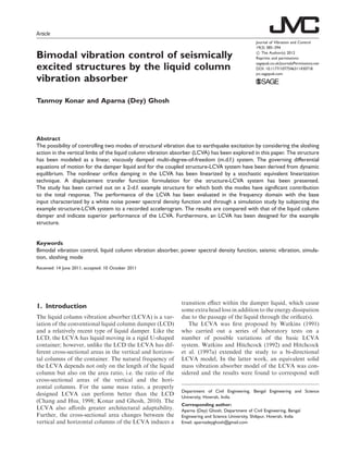
2. Modeling of the structure-LCVA
system
A linear, viscously damped, n-d.f structure with an
LCVA rigidly attached to the top mass of the structure,
subjected to horizontal ground acceleration, €z tð Þ, has
been investigated (see Figure 1(a)). The structural
parameters, such as mass matrix, stiffness matrix and
damping matrix are represented by M½ Š, K½ Š and C½ Š
respectively. The mass of the LCVA container is
assumed to be lumped with the mass of the nth
d.f. of
the structure. Figire 1b shows the model of the LCVA
alone in detail. The horizontal width of the LCVA, B,
denotes the center to center distance between the verti-
cal limbs of the damper. The vertical height of liquid, h,
is the distance measured from the central line of the
horizontal column to the still water level of the
LCVA. H indicates the length of the damper and ls
represents half the width of the vertical liquid
column. The depth of the horizontal limb of the
damper is dh. The mass density of the damper liquid
is . The coefficient of head loss, controlled by the
opening ratio of the orifice(s) and the geometry of the
damper, is denoted by . The cross-sectional areas of
the vertical and horizontal columns of the LCVA are
Av, and Ah respectively. To increase the effectiveness of
the LCVA, Av is greater than Ah, which will induce
sloshing in the vertical limbs of the damper. The por-
tions of the liquid, which are in the vertical limbs and
386 Journal of Vibration and Control 19(3)
3. above the center line of the horizontal column of the
LCVA, are considered to experience sloshing when sub-
jected to horizontal excitation and are indicated by the
hatched portions in Figure 1(b).
The fundamental sloshing modes of vibration in the
two vertical limbs are modeled by two equivalent s.d.f.
spring-mass-dashpot systems (see Veletsos and Tang,
1990) as shown in Figure 1(c). The liquid masses par-
ticipating in the fundamental sloshing modes for the
left and right limbs of the LCVA are denoted by m1
and m2 respectively. The corresponding stiffness and
damping are represented by k1, c1 and k2, c2 respec-
tively. Further, u1 tð Þ and u2 tð Þ are the displacement
coordinates of the equivalent s.d.f. systems representing
the sloshing of liquid in the left and right vertical col-
umns of the LCVA respectively. As the geometry of the
left and right vertical limbs of the LCVA are identical
and both are subjected to the same input excitation,
m1 ¼ m2 ¼ m, c1 ¼ c2 ¼ c, k1 ¼ k2 ¼ k ð1Þ
The expression for m as given by Housner (1957) is
as below.
m ¼ ms
1
3
ffiffiffi
5
2
r
ls
h
tanh
ffiffiffi
5
2
r
h
ls
!
ð2Þ
where, ms is the mass of the sloshing liquid in each limb
and given by
ms ¼ 2lsHh ð3Þ
KnCn
Mn
LCVA
xn(t)
y(t)
M1
K1C1
)(tz¨
x1(t)
Mj
KjCj
xj(t)
M2
K2C2
x2(t)
K3C3
Kj+1Cj+1
h
ls ls
H
Still water
level
Experience
sloshing
C of
horizontal limb
dh
B
L
Mn
k1
c1 m1
k2
c2 m2
u1(t) u2(t)
( )t
KnCn
K1C1
xn(t)
z¨
(a) (b)
(c)
Figure 1. (a) n-degree-of-freedom structure-liquid column vibration absorber model, (b) Model of the liquid column vibration
absorber, (c) Model of sloshing modes of vibration of liquid column vibration absorber.
Konar and Ghosh 387
4. Let x tð Þ
È É
denote the displacements along the d.f.s of
the structure relative to the ground and yðtÞ be the
change in elevation of the liquid column in the damper.
3. Formulation of transfer function
The equation of motion for the oscillating liquid
column of the LCVA may be derived by considering
the dynamic equilibrium of the liquid in the horizontal
limb of the LCVA. The different horizontal forces
acting on the liquid in the horizontal portion of the
LCVA are shown in Figure 2. The inertia force of
the liquid in the horizontal portion of the LCVA can
be expressed as,
F1 ¼ AhB €xnðtÞ þ r€yðtÞ þ €zðtÞ
È É
ð4Þ
where, r is the area ratio which is given by Av=Ahð Þ and
€xnðtÞ þ r€yðtÞ þ €zðtÞ
È É
, is the absolute acceleration of the
liquid in the horizontal portion of the damper.
The force due to head loss caused by the orifice and
sudden change in the cross-sectional area between ver-
tical and horizontal portion of the LCVA is given by,
F2 ¼
1
2
Ahr2
j _yðtÞj _yðtÞ ð5Þ
where, r_yðtÞ
È É
is the velocity of liquid in the horizontal
portion of the LCVA.
The hydrostatic pressure force from the left limb of
the damper on the horizontal portion may be written as,
F3 ¼ Ah h À yðtÞ
È É
g À €yðtÞ
È É
 Ã
ð6Þ
where, g is the acceleration due to gravity. Similarly the
hydrostatic pressure force from the right limb of the
damper on the horizontal portion can be expressed as,
F4 ¼ Ah h þ yðtÞ
È É
g þ €yðtÞ
È É
 Ã
ð7Þ
On consideration of the horizontal dynamic equilib-
rium of the liquid in the horizontal portion of the
LCVA, we get,
F1 þ F2 À F3 þ F4 ¼ 0 ð8Þ
which leads to the following expression,
AhLe €yðtÞ þ
1
2
Ahr2
_yðtÞ
_yðtÞ þ 2gAhyðtÞ
¼ ÀAhB €xnðtÞ þ €zðtÞ
È É
ð9Þ
where, Le denotes the effective length of the LCVA,
defined as,
Le ¼ Br þ 2hf g ð10Þ
An equivalent linear equation corresponding to
the nonlinear equation given by equation (9) may be
written as,
AhLe €yðtÞ þ 2AhCp _yðtÞ þ 2gAhyðtÞ
¼ ÀAhB €xnðtÞ þ €zðtÞ
È É
ð11Þ
where, Cp represents the equivalent linearized damping
coefficient which may be obtained by minimizing the
mean square value of the error incorporated due to
this linearization. Cp is expressed as
Cp ¼
r2
_y
ffiffiffiffiffiffi
2
p ð12Þ
where, 2
_y is the standard deviation of the liquid veloc-
ity, _y tð Þ, which is modeled as a zero mean stationary
Gaussian process. On normalizing equation (11) with
respect to AhLe we obtain,
€yðtÞ þ
2Cp
Le
_yðtÞ þ !2
l yðtÞ ¼ À €xnðtÞ þ €zðtÞ
È É
ð13Þ
where, !l ¼
ffiffiffiffiffiffiffiffiffiffiffiffi
2g=Le
p Ã
is the natural frequency of the
LCVA, i.e., the oscillating frequency of the liquid in
the LCVA and ¼ B=Le½ Š is the length ratio i.e., the
ratio of the length of the horizontal portion of the
LCVA to its effective length.
The force transmitted from the LCVA to the struc-
ture due to liquid oscillation may be expressed as,
Fos ¼ AhB €xnðtÞ þ r€yðtÞ þ €zðtÞ
È É
þ 2Avh €xnðtÞ þ €zðtÞ
È É
ð14Þ
The equations of motion for the masses of the s.d.f.
systems representing the fundamental sloshing modes
of the liquid in the left and right limbs of the damper
are given by
m1 €u1 tð Þ þ €xn tð Þ þ €z tð Þ
È É
þ c1 _u1 tð Þ þ k1u1 tð Þ ¼ 0 ð15Þ
m2 €u2 tð Þ þ €xn tð Þ þ €z tð Þ
È É
þ c2 _u2 tð Þ þ k2u2 tð Þ ¼ 0 ð16Þ
{ })()()( tz¨x¨ tÿrtn ++
F3 F4
F2F1
Figure 2. Forces acting on the liquid in the horizontal portion
of the liquid column vibration absorber.
388 Journal of Vibration and Control 19(3)
5. As the left and the right vertical limbs of the LCVA
are geometrically identical and both are subjected to
same base motion,
u1 tð Þ ¼ u2 tð Þ ¼ u tð Þ ð17Þ
With reference to equations (1) and (17), equa-
tions (15) and (16) reduce to
m €u tð Þ þ €xn tð Þ þ €z tð Þ
È É
þ c_u tð Þ þ ku tð Þ ¼ 0 ð18Þ
On normalizing equation (18) with respect to m,
we get,
€u tð Þ þ €xn tð Þ þ €z tð Þ
È É
þ 2
_u tð Þ þ
2
u tð Þ ¼ 0 ð19Þ
where,
and denote the frequency and damping ratio
of the equivalent s.d.f. systems.
The natural frequency of liquid sloshing in the fun-
damental mode has been expressed by Housner (1957).
Thus,
¼
ffiffiffi
5
2
r
g
ls
tanh
ffiffiffi
5
2
r
h
ls
!1=2
ð20Þ
The damping ratio is taken as 0.01 (Veletsos and
Tang, 1990).
The total force transmitted from the LCVA to the
structure due to the sloshing of liquid is given by,
Fsl ¼ c1 _u1 tð Þ þ k1u1 tð Þ þ c2 _u2 tð Þ þ k2u2 tð Þ
È É
ð21Þ
which may be simplified as,
Fsl ¼ 2 c_u tð Þ þ ku tð Þ
È É
ð22Þ
The equations of motion for the masses, M½ Š, of the
multi-d.f. system may be written as,
M½ Š €xðtÞ
È É
þ C½ Š _xðtÞ
È É
þ K½ Š xðtÞ
È É
¼ À M½ Š 1f g€zðtÞ þ f ðtÞ
È É
ð23Þ
Here, f ðtÞ
È É
¼ 0 :: :0 vðtÞ
È ÉT
denotes the inter-
active force between the structure and the damper with
vðtÞ being expressed as
v tð Þ ¼ 2 c_u tð Þ þ ku tð Þ
È É
À AhB €xn tð Þ þ r€y tð Þ
ÈÂ
þ€z tð Þ
É
þ 2Avh €xn tð Þ þ €z tð Þ
È ÉÃ
ð24Þ
As the structure is assumed to be classically damped,
it is possible to expand its response in terms of the
orthogonal mode shapes in the following way,
xðtÞ
È É
¼ ½ Š qðtÞ
È É
ð25Þ
where, ½ Š is the real valued modal matrix of the struc-
ture and qðtÞ
È É
is the vector of normal co-ordinates. On
using orthogonality relationships, the decoupled equa-
tion for the jth
mode of the structure is
€qj ðtÞ þ 2j!j _qj ðtÞ þ !2
j qj ðtÞ ¼ Àj €zðtÞ
þ jð Þ
È ÉT
f ðtÞ
È É
, for j ¼ 1, 2, . . . , n ð26Þ
where, jð Þ
È ÉT
is the transpose of the jth
mode shape and
j is the jth
modal participation factor given by
ð j Þ
È ÉT
M½ Š 1f g. Further, in equation (26), !j and j
denote the undamped natural frequency and damping
ratio in the jth
mode respectively. In equation (26),
jð Þ
È ÉT
f ðtÞ
È É
may be written as jð Þ
n vðtÞ
È É
, where jð Þ
n is
the nth
element of jð Þ
È É
. The Fourier transformation of
equation (26) leads to,
Q jð Þ
!ð Þ ¼ H jð Þ
!ð Þ ÀjA !ð Þ þ ’ jð Þ
n V !ð Þ
È É
,
for j ¼ 1, 2, . . . . . . : , n ð27Þ
where, H jð Þ
ð!Þ represents the modal transfer function
relating the displacement response of the s.d.f. system
in the jth
structural mode to the input ground acceler-
ation and may be expressed as,
H jð Þ
ð!Þ ¼
1
!2
j
À !2 þ 2ij!j!
,
for j ¼ 1, 2, . . . . . . : , n ð28Þ
In equation (27), Q jð Þ
ð!Þ, Vð!Þ and A !ð Þ represent
the Fourier transforms of the time dependent variables,
qj ðtÞ, vðtÞ and €zðtÞ respectively. The expression for Vð!Þ
is obtained by the Fourier transformation of equation
(24) and is given by,
V !ð Þ ¼ À AhB À!2
Xn !ð Þ À r!2
Y !ð Þ þ A !ð Þ
È ÉÂ
þ2Avh À!2
Xn !ð Þ þ A !ð Þ
È ÉÃ
þ2 i!c þ kð Þ U !ð Þ ð29Þ
where, Xnð!Þ, Yð!Þ and Uð!Þ are the Fourier trans-
forms of the corresponding time-dependent variables
xnðtÞ, yðtÞ and uðtÞ respectively.
The Fourier transformation of equation (13)
leads to,
Y !ð Þ ¼ H1 !ð Þ !2
Xn !ð Þ À A !ð Þ
È É
ð30Þ
where, H1ð!Þ is the transfer function relating the verti-
cal liquid displacement of the LCVA to the ground
acceleration and the expression is given by,
Konar and Ghosh 389
6. H1 !ð Þ ¼
1
!2
l À !2 þ 2Cp=Le
À Á
i!
ð31Þ
On taking the Fourier transformation of equation
(19), the following equation is obtained,
U !ð Þ ¼ H !ð Þ !2
Xn !ð Þ À A !ð Þ
È É
ð32Þ
where, Hð!Þ is the transfer function relating the dis-
placement of equivalent s.d.f. systems representing the
sloshing of liquid of the LCVA to the ground acceler-
ation and may be expressed as,
Hð!Þ ¼
1
2 À !2 þ 2i
!
ð33Þ
From equation (25) the displacement of the kth
d.f.
of the structure may be expressed in the frequency
domain as,
X Kð Þð!Þ ¼
Xn
j¼1
jð Þ
k Q jð Þ
ð!Þ, for k ¼ 1, 2, . . . . . . , n ð34Þ
Substitution of equations (27), (29), (30) and (32) in
equation (34) leads to the following linear, simulta-
neous equations which describe the displacements of
the d.fs of the structure in the frequency domain.
X Kð Þ !ð Þ À !2
Xn !ð Þ
È É Xn
j¼1
T jð Þ
kð Þ !ð Þ
¼ À
Xn
j¼1
’ jð Þ
kð ÞH jð Þ
!ð Þj þ T jð Þ
kð Þ !ð Þ
n o
#
A !ð Þ,
for k ¼ 1, 2, . . . : , n ð35Þ
where,
T jð Þ
kð Þ !ð Þ ¼ ’ jð Þ
kð ÞH jð Þ
!ð Þ’ jð Þ
n 2 H !ð Þ i!c þ kð Þ þ m0
Â
þAhrB!2
H1 !ð Þ
Ã
ð36Þ
In equation (36), m0 ¼
Pn
j¼1
Mj
#
represents the total
mass of the structure and ¼ BAh þ 2hAvð Þ=mo½ Š is
the mass ratio, defined as the ratio of the mass of the
liquid in the damper to that of the structure.
On solving the set of simultaneous equations given
by equation (35), the transfer functions, each relating
the displacement along a d.f. of the structure to the
ground acceleration can be obtained. If the earthquake
ground acceleration is characterized by a power spectral
density function (PSDF), then the PSDF of a response
quantity may be evaluated and the corresponding
root-mean-square (r.m.s.) value estimated (Newland,
1993).
4. Numerical study
4.1. Example structure and LCVA system
To demonstrate the effectiveness of the LCVA to con-
trol two modes of vibration of the structure, an exam-
ple structure should be so chosen such that two or more
modes participate significantly in the response of the
structure. Tapered buildings, which have more than
one mode contributing significantly to the horizontal
displacement response, may be considered for this pur-
pose. An example of this kind of tapered building is the
Transamerica building in San Francisco. The first two
frequencies of this pyramid-shaped building are
0.330 Hz and 0.616 Hz respectively (Stephen et al.,
1973). In this paper, a two-d.f. structure having the
same natural frequencies as the first two frequencies
of the Transamerica building is considered. The
masses lumped at the first and second story levels are
assumed to be 462.19 tons and 194.72 tons respectively.
The structural damping ratio is assumed to be 2%.
The LCVA parameters which are generally guided
by practical constraints like availability of space, load
carrying capacity of structure etc., are the mass ratio
() and length ratio (). The values of and for the
case under study here are taken as 1.5% and 0.7 respec-
tively. For this chosen value of the maximum value of
area ratio (r) is 1.425 (refer to equation (10)), which is
derived from the condition that the height of the liquid
in the vertical limbs (h) should not be negative. As has
been mentioned earlier, greater r leads to higher
response reduction. However, to maintain the
U-shape of the liquid h obviously has some positive
value and so a value of r lower than the optimum
value has to be considered. Considering the range
between 1.0 to 1.425, the value of r for this study has
arbitrarily been taken as 1.25. The liquid in the damper
is considered to be water.
4.2. Frequency domain study
The frequency domain study has been carried out on
the example structure-LCVA system described above.
The structure is considered to be subjected to an earth-
quake ground motion, characterized by a white noise
PSDF of intensity (So) equal to 100 cm2
/s3
. The modal
participation factors indicate that the predominant
mode in horizontal vibration is the first mode. As the
oscillating frequency of the water in the LCVA is lower
than the sloshing frequency of the water in the vertical
limbs of the LCVA, the former is tuned to the funda-
mental frequency of the structure with tuning ratio,
390 Journal of Vibration and Control 19(3)
7. [¼ !l=!s, i.e., the ratio of the oscillating frequency of
the liquid in the LCVA to the fundamental frequency
or first modal frequency of the structure (!s)]. The
sloshing frequency of the damper is tuned to the
second modal frequency of the structure with tuning
ratio equal to unity.
The optimum values of and
, are considered as
those which minimize the r.m.s. displacement of the top
mass of the structure. These are obtained here by eval-
uating the aforementioned response quantity as per the
formulation given in Section 3, for values of ranging
from 0.001 to 100 and
ranging from 0.75 to 1.1 for
each value of . For this particular example, the opti-
mum values of and
are respectively found to be 2.16
and 0.952.
In Figure 3, the displacement transfer functions for
the top mass of the structure without and with LCVA
have been presented, together with that obtained for the
structure with LCD instead of LCVA. In case of the
LCD, only the single frequency of the oscillating liquid
is considered, which is tuned to the fundamental struc-
tural mode with tuning ratio,
0
. The optimum values of
the head loss coefficient, 0
, and tuning ratio,
0
, for the
LCD, have been evaluated as 1.50 and 0.983 respec-
tively. The transfer function curves in Figure 3 clearly
indicate the tuning effect of the oscillating and sloshing
modes of the liquid in the LCVA on the two modes of the
structure, while the LCD affects only the first mode of
the structure. A considerable reduction of 39.70% in the
r.m.s. displacement response of the top mass of the
structure is achieved in case of the LCVA. For the
LCD, the corresponding reduction is 33.66%.
4.3. Simulation study
A time history analysis of the same example structure-
LCVA system, is conducted with a recorded accelero-
gram. The accelerogram considered is the recorded
N78E component of the Bhuj (2001) earthquake at
the Ahmedabad (23.03
N, 72.63
E) site. Integration
of the response of the structure-damper system in
time domain is done using the fourth-order Runge-
Kutta method. For simplicity, both the oscillating
mode as well as the sloshing mode have been tuned to
the structural modes with tuning ratio equal to unity.
The optimum value of is obtained by minimizing the
r.m.s. value of displacement of the top mass of the
structure and is found to be 8.20. The displacement
time histories of the top mass of the structure subjected
to the Bhuj excitation, without damper, with LCVA
and with LCD, have been plotted in Figure 4. The per-
centage response reductions of the structure-LCVA
system with respect to the structure alone case are
32.61% in the peak displacement, and 48.90% in the
r.m.s. displacement. The LCD, on the other hand, with
the same mass ratio ð Þ, length ratio () and tuning
ratio (
) as the LCVA, achieves 25.79% reduction
in the peak displacement response and 44.55% reduc-
tion in the r.m.s. displacement response of the same
structure.
0.0001
0.0010
0.0100
0.1000
1.0000
10.0000
0 1 2 3 4 5 6 7 8 9 10
ω (rad/s)
IH
(n)
(ω)I
without damper
with LCVA
with LCD
Figure 3. Displacement transfer function for the top mass of the structure for white noise input.
Konar and Ghosh 391
8. 5. Design of LVCA for example structure
In this section, an attempt has been made to design
the LCVA for the example structure considered in the
foregoing section. The seismic input is assumed to be
the recorded accelerogram of the Bhuj (2001) earth-
quake as considered earlier. The main aspect of the
design is to determine the geometric dimensions of
the LCVA for the mass of the liquid used in the
LCVA. The design has been carried out by keeping in
mind the geometric constraints in conjunction with
optimum response reduction. Based on the response
reduction required, availability of the space and prac-
tical feasibility, the mass ratio is considered. The load
carrying capacity of the structure should also be con-
sidered during the selection of mass ratio, especially if
the LCVA is to be installed in an existing structure.
As it is not practicable to go for a very high mass
ratio, ¼ 1.5% is adopted. As the total mass of the
structure is equal to 656,917 kg, the mass of water in
the damper, mw, equals 9853.755 kg. From the geomet-
ric constraint that the vertical height of the liquid in the
LCVA should be at least equal to the greater of half the
vertical depth of the horizontal column of the LCVA
and the maximum liquid displacement in the vertical
limbs, the length ratio () and the area ratio rð Þ are
considered as 0.5 and 1.25 respectively. By tuning the
oscillating frequency of the LCVA to the fundamental
frequency of the structure with tuning ratio equal to
unity, the effective length of the LCVA, Le, and the
horizontal width, B[ ¼ Le], are obtained as 4.562 m
and 2.281 m respectively. The vertical height of the
liquid in the LCVA, h [¼ (Le – Br)/2], is evaluated as
0.855 m. The horizontal cross-sectional area, Ah [¼ mw/
(B þ 2rh)] is obtained as 2.2295 m2
and the vertical
cross-sectional area, Av [¼ Ah r] is 2.7869 m2
. The
dimension ls of the sloshing liquid column is obtained
by tuning the sloshing frequency of the LCVA with the
second natural frequency of the structure and this
yields the value of ls as 0.939 m. Thus, the length of
the sloshing liquid column in the direction perpendicu-
lar to the direction of sloshing, H [¼ Av/ls] is 1.483 m
and the depth of the horizontal column of the LCVA,
dh [¼ Ah/H] is 1.503 m. The inner dimensions of the
LCVA in plan are obtained as 4.160 m  1.483 m.
The evaluation of the orifice opening ratio (¼ cross-
sectional area of the orifice/cross-sectional area of the
tube) is based on the optimum value of the head loss
coefficient, opt. opt is obtained by minimizing the r.m.s.
value of the tip structural displacement and the value is
7.70. Wu (2005) has provided an empirical formula
relating the head loss coefficient and the blocking
ratio, , from their experiments. The expression is
given by
¼ ðÀ0:6 þ 2:1 0:1
Þ1:6
ð1 À ÞÀ2
ð37Þ
For the case under study here, the solution of equa-
tion (37) for ¼ 7:7 leads to a blocking ratio of 0.4575.
Consequently, the opening of the orifice is obtained as
about 0.815 m. The maximum depth of the liquid is
1.831 m. In addition to this some free board should
be provided. Considering a free board of 0.269 m, the
total height of the LCVA is 2.10 m. Thus, a feasible
geometric configuration is obtained for the LCVA
(see Figure 5).
The performance of the LCVA designed for the
example structure is assessed through a simulation
Displacement(m)
0.20
0.15
0.10
0.05
0.00
–0.05
–0.10
–0.15
–0.20
0 10 20 30 40 50 60 70
Time (s)
80 90 100 110 120 130
Without damper
With LCD
With LCVA
Figure 4. Displacement time history of 2-degree-of-freedom system for Bhuj (2001) excitation.
392 Journal of Vibration and Control 19(3)
9. study with the recorded accelerogram of the Bhuj
(2001) earthquake as the seismic input. The displace-
ment responses of the top mass of the structure with
and without the designed LCVA are shown in Figure 6.
The incorporation of the LCVA achieves considerable
response mitigation, and it reduces the r.m.s. response
by 41.03% and the peak response by 20.84%.
6. Conclusions
In this paper, the sloshing of liquid in the vertical limbs
of the liquid column in the LCVA has been modeled
along with the oscillation of the liquid column for
bimodal vibration control of a structure modeled as a
linear, viscously damped m.d.f. system. The transfer
functions of the structural displacement responses
with LCVA, considering both sloshing and oscillating
liquid motions, to the input ground acceleration have
been formulated. The transfer function for the tip dis-
placement of an example two-d.f. structure, with and
without LCVA, indicates that control has been
achieved in both structural modes of vibration. The
reduction obtained in the response of the example
structure to white noise ground PSDF by the LCVA
–0.20
–0.15
–0.10
–0.05
0.00
0.05
0.10
0.15
0.20
0 10 20 30 40 50 60 70 80 90 100 110 120 130
time (s)
displacement(m)
without damper
with the designed
LCVA
Figure 6. Displacement time history of the example structure for Bhuj (2001) excitation.
Note: a) All dimensions are in mm.
b) The values indicated are the inner dimensions of the container.
1483
815
1503104
4160
4041878 1878
1607493
Figure 5. Detailing of the designed liquid column vibration absorber.
Konar and Ghosh 393
10. is greater than that by the LCD. A simulation study
using a real accelerogram yields similar results. Finally,
an LCVA has been designed for the example structure
subjected to a recorded accelerogram.
Funding
This research received no specific grant from any funding
agency in the public, commercial, or not-for-profit sectors.
References
Chaiviriyawong P, Webster WC, Pinkaew T and
Lukkunaprasit P (2007) Simulation of characteristics of
tuned liquid column damper using a potential-flow
method. Engineering Structures 29(1): 132–144.
Chang CC and Hsu CT (1998) Control performance of liquid
column vibration absorbers. Engineering Structures 20(7):
580–586.
Chang CC and Qu WL (1998) Unified Dynamic Absorber
Design Formulas For Wind-Induced Vibration Control Of
Tall Buildings. New York: John Wiley Sons Ltd.
Hitchcock PA, Kwok KCS, Watkins RD and Samali B
(1997a) Characteristics of liquid column vibration absor-
bers (LCVA)–I. Engineering Structures 19(2): 126–134.
Hitchcock PA, Kwok KCS, Watkins RD and Samali B
(1997b) Characteristics of liquid column vibration absor-
bers (LCVA)–II. Engineering Structures 19(2): 135–144.
Hitchcock PA, Glanville MJ, Kwok KCS, Watkins RD and
Samali B (1999) Damping properties and wind-induced
response of a steel frame tower fitted with liquid column
vibration absorbers. Journal of Wind Engineering and
Industrial Aerodynamics 83: 183–196.
Housner GW (1957) Dynamic pressures on accelerated fluid
containers. Seismological Society of America 47(1): 15–35.
Kim HJ, Kim WJ, Lee SG, Jo JS, Kim DK and Lee KJ (2008)
Mitigation of wind-induced vibration with liquid column
vibration absorber. Advances in Science and Technology
56: 259–264.
Konar T and Ghosh AD (2010) Passive control of seismically
excited structures by the liquid column vibration absorber.
Structural Engineering and Mechanics 36(5): 561–573.
Newland DE (1993) An Introduction to Random Vibrations,
Spectral and Wavelet Analysis. New York and London:
Longman, 73.
Samali B, Mayol E, Kwok KCS, Mack A and Hitchcock P
(2001) Damping enhancement of a 5 story benchmark
building using liquid column vibration absorbers. In
Proceedings of the First International Conference on Fluid
Structure Interaction, 26th–28th September 2001,
Halkidiki, Greece, pp. 235–244.
Samali B, Mayol E, Kwok KCS, Mack A and Hitchcock P
(2004) Vibration control of the wind-excited 76-story
benchmark building by liquid column vibration absorbers.
Journal of Engineering Mechanics 130(4): 478–485.
Stephen RM, Hollings JP and Bouwkamp JG (1973)
Dynamic behavior of multistory pyramid-shaped building.
Berkeley, Earthquake Engineering Research Center Report
EERC 73–17.
Taflanidis AA, Demos CA and George CM (2005) Optimal
design and performance of liquid column mass dampers
for rotational vibration control of structure under white
noise excitation. Engineering Structures 27: 524–534.
Taflanidis AA, Beck JL and Angelides DC (2007) Robust
reliability-based design of liquid column mass damper
under earthquake excitation using an analytical reliability
approximation. Engineering Structures 29: 3525–3537.
Veletsos AS and Tang Y (1990) Soil-structure interaction
effects for laterally excited liquid storage tanks. Earthquake
Engineering and Structural Dynamics 19: 473–496.
Watkins RD (1991) Tests on various arrangements of liquid
column vibration absorbers. Research report No R639,
School of Civil and Mining Engineering.
Watkins RD and Hitchcock PA (1992) Model tests on two-
way liquid column vibration absorber. Research report No
656, School of Civil and Mining Engineering.
Wu JC (2005) Experimental calibration and head loss predic-
tion of tuned liquid column damper. Tamkang Journal of
Science and Engineering 8(4): 319–325.
Wu JC, Wang YP, Lee CL, Liao PH and Chen YH (2008)
Wind-induced interaction of a non-uniform tuned liquid
column damper and a structure in pitching motion.
Engineering Structures 30(12): 3555–3565.
Wu JC, Chang CH and Lin YY (2009) Optimal designs for
non-uniform tuned liquid column dampers in horizontal
motion. Journal of Sound and Vibration 326: 104–122.
394 Journal of Vibration and Control 19(3)