1. Annu. Rev. Fluid Mech. 2002. 34:503–29
Copyright°c 2002 by Annual Reviews. All rights reserved
SYNTHETIC JETS
Ari Glezer1 and Michael Amitay2
1George W. Woodruff School of Mechanical Engineering, Georgia Institute of Technology,
Atlanta, Georgia 30332-0405; e-mail: ari.glezer@me.gatech.edu
2Aerospace, Transportation, and Advanced Systems Laboratory, Georgia Technical
Research Institute, Atlanta, Georgia 30332-0800; e-mail: michael.amitay@me.gatech.edu
Dedicated to Professor D.E. Coles,
who conceived synthetic shear flows.
Key Words synthetic jets, vortices, jet cross-flow interaction, turbulence,
boundary-layer separation, aerodynamic forces
n Abstract The evolution of a synthetic (zero-net mass flux) jet and the flow mech-anisms
of its interaction with a cross flow are reviewed. An isolated synthetic jet is
produced by the interactions of a train of vortices that are typically formed by alternating
momentary ejection and suction of fluid across an orifice such that the net mass flux is
zero.Aunique feature of these jets is that they are formed entirely from theworking fluid
of the flow system in which they are deployed and, thus, can transfer linear momentum
to the flow system without net mass injection across the flow boundary. Synthetic jets
can be produced over a broad range of length and timescale, and their unique attributes
make them attractive fluidic actuators for a number of flow control applications. The
interaction of synthetic jets with an external cross flow over the surface in which they
are mounted can displace the local streamlines and induce an apparent or virtual change
in the shape of the surface, thereby effecting flow changes on length scales that are one
to two orders of magnitude larger than the characteristic scale of the jets. This control
approach emphasizes an actuation frequency that is high enough so that the interaction
domain between the actuator and the cross flow is virtually invariant on the global
timescale of the flow, and therefore, global effects such as changes in aerodynamic
forces are effectively decoupled from the operating frequency of the actuators.
1. OVERVIEW
Jet-like flows having complex spatial and temporal characteristics can be engen-dered
in a quiescent medium (or in a cross flow) by the advection and interactions
of trains of discrete vortical structures (e.g., Saffman 1981). The hydrodynamic
impulse that is necessary to form each of these vortices is imparted at the flow
boundary by the momentary discharge of slugs of fluid through an orifice. The
flow typically separates at the edge of the orifice, and a vortex sheet is formed
and rolls into an isolated vortex that is subsequently advected away under its own
self-induced velocity. Depending on the flow symmetry and the repetition rate, the
dynamics and interactions of the vortical structures within a pulsed jet can lead to
0066-4189/02/0115-0503$14.00 503
Annu. Rev. Fluid Mech. 2002.34:503-529. Downloaded from www.annualreviews.org
by Universite De Poitiers on 09/08/12. For personal use only.
2. 504 GLEZER ¥ AMITAY
spatial evolution that is remarkably different from the evolution of a continuous
(conventional) jet having the same orifice and time-averaged flux of streamwise
momentum. Moreover, discrete vortical structures can also be formed within a
continuous jet by deliberate temporal modulation of its streamwise momentum
flux, which, depending on the degree and frequency of modulation, can lead to
radical modification of the unmodulated jet. For example, Lee & Reynolds (1985)
demonstrated that small changes in the azimuthal formation of successive vortex
rings in a circular jet can alter their trajectories and result in spectacular far-field
“bifurcation” or “blooming.”
“Synthetic” jet flows are similar to pulsed jets in that they are also produced by
the advection and interactions of trains of discrete vortical structures. However, a
unique feature of synthetic jets is that they are formed entirely from the working
fluid of the flow system in which they are deployed and, thus, can transfer linear
momentum to the flowsystem without net mass injection across the flowboundary.
The fluid that is necessary to synthesize the jet is typically supplied by intermittent
suction through the same flow orifice between consecutive ejections. Because the
characteristic dimensions of the ensuing jet scale with the orifice, it is possible,
in principle, to synthesize jets over a broad range of length scales [e.g., synthetic
jets having a nominal orifice dimension of 150 ¹m were fabricated using standard
silicon micromachining techniques by Coe et al. (1994, 1995), and more recently
Muller et al. (2001) reported microfabricated jet arrays].
The oscillating (time-reversed) pressure drop across an orifice that is neces-sary
to form a synthetic jet can be imposed by an acoustic field, provided that the
amplitude of the pressure oscillations is large enough to induce the time-periodic
roll-up and subsequent advection of discrete vortices. The impulse that is imparted
to each vortex has to be large enough to overcome the influence of both the orifice
image and the forces associated with the (reversed) suction flow. Ingard & Labate
(1950) used standing waves in an acoustically driven circular tube to induce an
oscillating velocity field in the vicinity of an end plate and observed the formation
of zero-net mass flux jets from opposing trains of vortex rings on both sides of
the orifice. In a later experiment, Lebedeva (1980) created a round jet with velo-cities
of up to 10 m/s, by transmitting high-amplitude sound waves through an ori-fice
placed at the end of a tube. In a related investigation, Mednikov & Novitskii
(1975) reported the formation of a jet without net mass flux and average streaming
velocities of up to 17 m/s, by inducing a low-frequency (10–100 Hz) oscillatory
velocity field at the end of a conical resonating tube driven by a piston and bellows
mechanism.
Streaming motions without mass addition can also be effected by the transmis-sion
of sound through the flow field (often referred to as acoustic streaming) or by
oscillating the boundary of a quiescent medium. Although these streaming flows
are produced without net mass flux, they are not typically accompanied by the
formation of discrete vortices that are inherent in the formation of synthetic jets by
fluid injection through an orifice. As noted by Lighthill (1978), the streaming mo-tions
induced by acoustic waves result from the dissipation of acoustic energy or
Annu. Rev. Fluid Mech. 2002.34:503-529. Downloaded from www.annualreviews.org
by Universite De Poitiers on 09/08/12. For personal use only.
3. SYNTHETIC JETS 505
the attenuation of the transmitted sound. Such attenuation can occur either within
the body of the fluid (i.e., away from solid surfaces) at very high frequencies or
owing to viscous effects near a solid boundary. Streaming motions associated with
moving (oscillating) solid boundaries have been the subject of a number of investi-gations,
most notably the time-harmonic oscillations of a cylinder normal to its axis
(e.g., Stuart 1966, Davidson & Riley 1972, Riley & Wibrow 1995). Davidson &
Riley demonstrated streaming velocities on the order of 1 cm/s inwater at a nominal
oscillation frequency of 45 Hz.
James et al. (1996) investigated the evolution of a synthetic round turbulent jet
that is formed in water without an orifice by a submerged oscillating diaphragm
that is flush mounted in a flat plate. These jets are produced without mass injection
normal to and at the center of the diaphragm and are comprised entirely from
radially entrained fluid. The jets are formed only when small clusters of cavitation
bubbles appear and subsequently collapse near the center of the diaphragm during
each oscillation cycle. The authors conjectured that the time-periodic formation of
these bubbles displaces vorticity from the actuator’s boundary layer and leads to
the formation of nominally axisymmetric turbulent vortices (e.g., Kovasznay et al.
1973) that coalesce to synthesize a turbulent jet. Similar to a conventional turbulent
round jet, the time-averaged width and the inverse of the centerline velocity of this
synthetic jet increase linearly with the distance from the actuator.
In recent years, plane and round synthetic jets that are formed by time-periodic
alternate ejection and suction of the working fluid through an orifice in the flow
boundary have been investigated both experimentally (Smith&Glezer 1997, 1998;
Smith et al. 1999; Mallinson et al. 1999; Crook et al. 1999, 2001; Rediniotis
et al. 1999; Chen et al. 2000; Muller et al. 2000, 2001) and numerically (Kral
et al. 1997; Rizzetta et al. 1998; Guo & Kral 2000). These investigations have
emphasized a compact flow generator in which the orifice forms one of the sur-faces
of an otherwise sealed shallow cavity where the flow is driven by the mo-tion
of a diaphragm (or a piston) that is built into one of the cavity walls. For a
given actuation input, the effectiveness of the flow generator can be maximized
when the diaphragm and cavity are driven at a coupled resonance that depends
on both the cavity flow (and geometry) and the structural characteristics of the
diaphragm.
The investigations of Smith&Glezer (1997, 1998) have shown that, near the jet
exit plane, the synthetic jet flow is dominated by the time-periodic formation, ad-vection,
and interactions of discrete vortical structures (e.g., vortex pairs or vortex
rings), which ultimately become turbulent, slow down, and lose their coherence.
Owing to the suction flow, the time-averaged static pressure near the exit plane of
a synthetic jet is typically lower than the ambient pressure and both the streamwise
and cross-stream velocity components reverse their direction during the actuation
cycle. The time-periodic reversal in flowdirection along the jet centerline (between
the blowing and suction strokes) leads to the formation of a stagnation point on
the centerline downstream of the orifice and confines the suction flow to a narrow
domain near the exit plane. These features as well as the celerity and characteristic
Annu. Rev. Fluid Mech. 2002.34:503-529. Downloaded from www.annualreviews.org
by Universite De Poitiers on 09/08/12. For personal use only.
4. 506 GLEZER ¥ AMITAY
length scale of the discrete vortices that form the jet can be varied over a broad
range by the amplitude and period of the diaphragm motion.
The interaction of a synthetic jet (or jet arrays) with an external cross flow
over the surface in which they are mounted can displace the local streamlines and
induce an apparent or virtual change in the shape of the surface and is, therefore,
of considerable interest for flow control applications. The control of aerodynamic
flows by modifying the apparent shape of aerosurfaces in order to prescribe the
streamwise pressure distribution and thereby influence their aerodynamic perfor-mance
is not new and was addressed in several investigations in the 1940s and
1950s. For example, Perkins & Hazen (1953) used a stationary trapped vortex to
alter the apparent local surface curvature and therefore the direction of the exter-nal
flow near the trailing edge of an airfoil to increase the lift at zero angle of
attack. In a recent investigation of the evolution of synthetic jets on the surface
of a two-dimensional cylinder, Honohan et al. (2000) demonstrated that when the
jets are operated on a timescale that is well below the characteristic timescale of
the base flow, the formation of a quasi-steady interaction domain near the surface
is accompanied by a more favorable pressure gradient. As a result, the surface
boundary layer downstream of this domain becomes thinner allowing the flow to
overcome stronger adverse pressure gradients and therefore delaying (or altogether
suppressing) flow separation.
The unique attributes of synthetic jets coupled with the development of actu-ators
that can be integrated into the flow surface without the need for complex
piping and fluidic packaging make them attractive fluidic actuators for control of
both external and internal flows. As noted above, apparent surface modification is
typically implemented by operating the jet actuator on timescales that are below
the characteristic timescale of the base flow. However, the unsteady effects of the
actuation can also be coupled to inherent instabilities of the base flow to affect
significant global modifications on scales that are one to two orders of magnitude
larger than the characteristic length scales of the jets themselves. The utility of
synthetic jets for flow control was demonstrated in the vectoring of conventional
jets in the absence of extended control surfaces by Smith & Glezer (1994, 1997)
and, in more detail, by Smith (1999). Since then, this approach to flow control has
been adopted in a number of other applications, including the modification of the
aerodynamic characteristics of bluff bodies (Amitay et al. 1997, 1998), control of
lift and drag on airfoils (Kral et al. 1997; Smith et al. 1998; Amitay et al. 1999,
2001; Seifert&Pack 1999), reduction of skin friction of a flat-plate boundary layer
(Lorkowski et al. 1997), mixing in circular jets (Davis&Glezer 1999), and control
of internal flow separation (Amitay et al. 2000) and of cavity oscillations (Fabris&
Williams 1999, Lamp & Chokani 1999).
The present review paper comprises two primary parts. In Section 2, the for-mation
and the near- and far-field evolution of isolated synthetic jets (i.e., in the
absence of a cross flow) are discussed. Section 3 focuses on the evolution of the
interaction domain between a synthetic jet and a cross flow on the surface of a
two-dimensional cylinder and the modification of the base flow.
Annu. Rev. Fluid Mech. 2002.34:503-529. Downloaded from www.annualreviews.org
by Universite De Poitiers on 09/08/12. For personal use only.
5. SYNTHETIC JETS 507
2. ISOLATED SYNTHETIC JETS
2.1. Jet Formation
An isolated synthetic jet in the absence of a cross flow is produced by the inter-actions
of a train of vortices that are typically formed by alternating momentary
ejection and suction of fluid across an orifice such that the net mass flux is zero.
Whereas the nominally axisymmetric (or two-dimensional) flowduring the suction
stroke may be thought of as similar to the flow induced by a sink that is coincident
with the jet orifice, the flow during the ejection stroke is primarily confined to a
finite narrow domain in the vicinity of the jet centerline. During the momentary
ejection, the flow separates at the sharp edges of the orifice and forms a vortex
sheet that typically rolls into a vortex (vortex rings or vortex pairs for circular or
two-dimensional orifices, respectively) that moves away from the orifice under its
own self-induced velocity (e.g., Auerbach 1987). The degree of interaction be-tween
the vortex and the reversed flow that is induced near the orifice by suction
of makeup fluid when the pressure drop across the orifice is reversed depends on
the strength (i.e., impulse) of the vortex and its distance from the orifice.
As noted in Section 1, synthetic jets are typically formed by imposing a time-periodic
alternating pressure drop across an orifice (e.g., by acoustic waves or by
the motion of a piston or a diaphragm). Recent investigations have employed a
variety of jet drivers including piezolectrically driven diaphragms (e.g., Smith &
Glezer 1997, 1998; Mallinson et al. 1999; Crook et al. 1999; Chen et al. 2000), elec-tromagnetically
driven pistons (e.g., Rediniotis et al. 1999, Crook &Wood 2001),
and acoustically driven cavities (e.g., Erk 1997, McCormick 2000, Kang et al.
2000). Crook et al. (1999) modeled the coupled structural and fluid characteristics
of a synthetic jet generator that employed a piezoelectrically driven diaphragm.
The flow was modeled using the unsteady Bernoulli equation, and the effects of
the orifice diameter and the cavity height on the jet flow were evaluated. Although
the agreement between the predicted and measured dependence of the centerline
velocity on orifice diameter and cavity height is poor, the trends are similar. More
recently, Chen et al. (2000) characterized piezoelectrically driven synthetic jet ac-tuators
using a variety of piezoceramic disc elements having different mechanical
properties and varying thickness and diameter.
The complex flow field within the actuator cavity has been primarily treated
numerically. For example, Rizzetta et al. (1998) used the unsteady compressible
Navier-Stokes equations for numerical simulations of both the flow within the
actuator cavity and the jet flow near the orifice where the time harmonic motion
is driven by a moving wall (opposite to the orifice). Two-dimensional simulations
were conducted for either a fixed Reynolds number or a fixed cavity height. During
the suction stroke, a counter-rotating vortex pair is formed at the inner edges of
the orifice, impinges on the opposite wall, and dissipates near the center of the
cavity (ostensibly owing to the injection of opposite sense vorticity from the wall
boundary layer) before the next ejection cycle begins. For a given Reynolds num-ber,
the strength of the vortex pairs that are produced on both sides of the orifice
Annu. Rev. Fluid Mech. 2002.34:503-529. Downloaded from www.annualreviews.org
by Universite De Poitiers on 09/08/12. For personal use only.
6. 508 GLEZER ¥ AMITAY
appears to increase with decreased cavity height (as was also confirmed in a later
investigation by Lee & Goldstein 2000). A comparison between time-averaged
velocity distributions downstream of the orifice of both two-dimensional and sep-arate
three-dimensional simulations and the earlier measurements of Smith &
Glezer (1997) yielded a reasonable agreement near the jet centerline.
In thework of Smith&Glezer (1998), a nominally high aspect ratio (AR D 150)
two-dimensional synthetic jet is formed in air through a rectangular orifice (0.5mm
wide) in a shallow (and otherwise sealed) cavity by piezoelectric diaphragms that
are mounted on one of the cavity walls (Figure 1a) and are driven at resonance
(nominally 1140 Hz). A Schlieren image in the x-y plane of the jet that extends
approximately through x=b D 70 (Figure 1b) shows a vortex pair that is formed
near the orifice as well as the outline of a turbulent jet farther downstream. Although
the vortex pair and the remainder of the ejected fluid appear to be laminar after
the roll-up is completed, the cores of the vortex pairs become unstable and begin
to break down to small-scale motions around t=T D 0:5 (i.e., at the beginning of
the suction flow). Similar to an isolated vortex ring (Glezer 1988), the onset of
small-scale transition appears to take place near the front stagnation point of the
vortex pair where the strain rates are high. Based on the Schlieren visualization,
the transition process seems to proceed toward the rear of the vortex and ultimately
progresses through the fluid stem behind it.
Axisymmetric vortex rings (e.g., Didden 1979, Glezer 1988) may be charac-terized
by two primary dimensionless parameters. The first parameter is the di-mensionless
“stroke” length L0=d(L0 D
R ¿
0 u0(t)dt, where u0(t) is the streamwise
velocity (averaged over the area of the orifice), ¿ is the time of discharge, and d is
the characteristic length scale of the orifice. The second parameter is the Reynolds
number based on the impulse (i.e., the momentum associated with the discharge)
and is given by ReI0
D I0=¹d, where I0 D ½
R ¿
0
R
A u20
(x; t)dA dt, where ½ and
¹ are the fluid density and viscosity, respectively. Alternative Reynolds numbers
may be defined based on the circulation of the ejected fluid or the time-averaged
orifice velocity during the ejection. For noncircular orifices, the aspect ratio of the
orifice may influence the out-of-plane distortion of the vortices and hence their
streamwise advection and evolution (e.g., Dhanak & Bernardinis 1981) and ul-timately
the streamwise variation of the jet cross section (e.g., Ho & Gutmark
1987). When the vortices are generated time-periodically to synthesize a jet, an
important formation parameter is the repetition rate or the formation frequency
f, where the dimensionless frequency F¤ D f I0=(½º2) is a measure of the total
impulse per unit time and thus may be used as a parameter that characterizes dif-ferent
jets according to their strength. Other formation parameters may include
the formation duty cycle (i.e., ¿=T) and an integral formation parameter that ac-counts
for different velocity programs during the ejection and suction strokes. The
characterization of the formation parameters of the jet is simplified when the jet
is driven time-harmonically, and the formation parameters depend primarily on
the frequency and amplitude of the driving mechanism (e.g., diaphragm or piston
motion) and cannot be varied independently.
Annu. Rev. Fluid Mech. 2002.34:503-529. Downloaded from www.annualreviews.org
by Universite De Poitiers on 09/08/12. For personal use only.
7. SYNTHETIC JETS 509
Some details of the formation of the jet vortices were studied by Rediniotis
et al. (1999) in a circular jet (D D 2 mm) driven by a shaker. For a given Reynolds
number (ReD D 200), the authors observed the formation of a jet for L0=D D 1.6
and St D 0:2 (based on the maximum exit velocity); while for L0=D D 0:16 and
St D 2, the ejected fluid was drawn back into the cavity during the suction stroke
and therefore no jet was formed. [In experiments on the formation of vortex rings
in the absence of suction, Didden (1979) noted that isolated vortex rings could
not be produced for L0=D < 0:4 over the same range of Reynolds numbers.]
In related flow-visualization experiments, Crook & Wood (2001) investigated the
formation and interaction of vortices within a round synthetic jet operating at
50 Hz (Figure 2). For four Reynolds numbers (between 660 and 2300, based on
the peak velocity at the orifice) and corresponding L0=D between 2.56 and 8.9,
the vortices increase in size, and there is virtually no interaction between successive
vortices. In fact, the turbulent vortices at ReD D 2300 resemble isolated turbulent
vortices, including the formation of secondary vortices within the wake, that were
observed by earlier investigators (e.g., Glezer 1988). However, for a low Reynolds
number (ReD D 330; L0=D D 1:28), the celerity of the successive vortices appears
to be low enough so that the motion is apparently affected by the buoyancy of the
tracer smoke particles.
2.2. Near-Field Evolution
It is clear that at least in the near field of the jet, its evolution depends critically on
the details of the formation and advection of the discrete vortices in the presence
of the time-periodic reversed flow. Smith & Glezer (1998) determined the celerity
Uc(x; t) of the vortex pairs (Figure 3a) from the time derivative of the phase-averaged
trajectories of the cores of a family of nominally two-dimensional vortex
pairs (for 1400 < I0=¹h < 30;000 and a fixed actuator frequency). The trajectories
of the vortex pairs appear to scale with L0, and they are made up of three distinct
domains that are characterized by substantial changes in the celerity. For 0:25 <
t=T < 0:5, the vortex pairs are nominally laminar and the celerity decreases like
(t=T )¡0:5 (a straight line segmentm D ¡0:5 is shown for reference). Based on flow
visualization, Smith & Glezer (1998) noted that the vortex pair begins to undergo
transition to turbulence approximately at the beginning of the suction cycle of the
actuator, which may in fact be triggered by core instabilities associated with the
reversal of the streamwise velocity near the exit plane. Following transition (0:5 <
t=T < 0:8), Uc(x; t) decreases like (t=T )¡2, which is faster than for the laminar
vortex pair and considerably faster than for an isolated turbulent vortex. The celerity
has a local minimum at t=T ¼ 0:8 and then increases like (t=T )2 until the vortex
pair becomes indistinguishable from the jet flow and its fluid effectively moves
with the mean flowof the jet. The authors noted that regardless of the total impulse,
no vortices are phase locked to the actuator signal much beyond t=T > 1:3.
In addition to the time-averaged centerline velocity Ucl(x) and the celerity, the
evolution of the jet near the exit plane may also be characterized by the magnitude
Annu. Rev. Fluid Mech. 2002.34:503-529. Downloaded from www.annualreviews.org
by Universite De Poitiers on 09/08/12. For personal use only.
8. 510 GLEZER ¥ AMITAY
Figure 3 (a) Variation of vortex-pair celerity with time. ReI0
D1;396 ( h), 3,171 (¤),
4,967 (§), 9,072 (4), 12,552 (r), 18,124 ( x), 20,761 (¥), 22,282 (¨), 27,025 (N), and
29,654 (H); (b) Mean centerline velocity (¤), celerity ( h), and residual velocity (}) for
ReI0
D18;124 (ReU0
D383). From Smith & Glezer (1998).
of the phase-averaged (relative to the actuation signal) residual centerline veloc-ity
between (i.e., before or after the passage of) successive vortices at a given
streamwise location. This residual velocity Ur (x) is, in part, a measure of the
time-invariant velocity of fluid that is entrained into the jet column by the suction
flow that is induced at the orifice. Figure 3b shows the streamwise variation of
Uc(x);Ur (x), and Ucl(x) in the near field (for ReI0
D 18;124) and shows that both
the celerity and the centerline velocity decrease substantially during transition to
turbulence (around x=b D 7). Furthermore, the celerity and the residual velocity
become equal to the time-averaged centerline velocity for x=b > 20. However,
the centerline velocity decreases like x¡0:58 (compared to x¡0:5 for conventional
two-dimensional turbulent jets) ostensibly as a result of the variation of the static
pressure in the vicinity of the orifice and the finite aspect ratio of the jet.
The time-periodic reversal in flow direction along the jet centerline during the
blowing and suction strokes leads to the time-periodic appearance of a stagnation
(saddle) point on the centerline (between the recent vortex and the jet exit plane) that
Annu. Rev. Fluid Mech. 2002.34:503-529. Downloaded from www.annualreviews.org
by Universite De Poitiers on 09/08/12. For personal use only.
9. SYNTHETIC JETS 511
Figure 4 Phase-averaged streamline maps computed (at t=T D 0:75) from particle
image velocimetry (PIV) data. f D 600 Hz, ReU0
D300, and L0=bD29:1.
moves along the centerline during the suction stroke. The presence of a stagnation
point in phase-averaged streamline maps of a two-dimensional jet (Figure 4) that
are computed from particle image velocimetry (PIV) data is shown by B.L. Smith
and A. Glezer (submitted). The stagnation point is located at x=b D 5 and the
stagnation streamlines on both sides of the stagnation point separate between the
flowthat is driven by the ejection stroke and the suction flow(toward the jet orifice).
The latter is restricted to the domain that is also bounded by the exit plane of the
jet and is nominally symmetric with respect to the jet centerline. The streamline
map also shows that the flow downstream of the branches of the stagnation point
on both sides of the centerline is directed toward the jet orifice and then turns
around in the streamwise direction near the cross-stream edges of the jet. These
authors also noted that the symmetry of the flow that is transported toward the
orifice during the suction stroke can be altered on either side of the jet center-line
by extending one of the edges of the jet orifice in the downstream direction
(the length of the extension is of the order of the orifice width) thus restricting the
suction flow on that side and increasing the flow rate on the opposite side of the jet
orifice. As shown by the authors, the ability to control the symmetry of the suction
flow plays an important role in the vectoring of conventional jets by synthetic jet
actuators.
2.3. Far-Field Evolution
The works of Smith & Glezer (1997) and Smith et al. (1999) in a two-dimensional
jet show that although cross-stream distributions of the time-averaged stream-wise
and cross-stream velocity components and the corresponding rms velocity
Annu. Rev. Fluid Mech. 2002.34:503-529. Downloaded from www.annualreviews.org
by Universite De Poitiers on 09/08/12. For personal use only.
10. 512 GLEZER ¥ AMITAY
fluctuations appear to collapse in the usual similarity coordinates, the streamwise
scaling of other variables (e.g., the centerline velocity, jet width, volume flow
rate, etc.) do not match corresponding scaling for conventional jets. For example,
whereas the width b of a two-dimensional synthetic jet varies like x0:88 (b / x for
a conventional two-dimensional jet), db=dx is almost twice as large as in conven-tional
jets at much higher Reynolds numbers (of order 104, e.g., Heskestad 1965).
Furthermore, even though the streamwise variation of the jet volume flow rate
dQ=dx is smaller than in conventional jets, the net entrained volume flow rate of
the synthetic jet within the domain x=b<80 is nearly 4Q0 (Q0 D U0b) and sub-stantially
larger than for conventional jets (e.g., Kotsovinos & Angelidis 1991).
The departure from conventional self-similarity is apparently associated with a
streamwise decrease in the jet’s momentum flux, which is typically assumed to be
an invariant of the flow for conventional self-similar two-dimensional jets. This
decrease in the momentum flux of synthetic jets is a result of the adverse stream-wise
pressure gradient near the jet orifice that is imposed by the suction cycle of
the actuator and is manifested by a time-averaged static pressure, which is lower
than the ambient.
In a related numerical investigation (using RANS) of an isolated two-dimensional
synthetic jet, Kral et al. (1997) considered a two-dimensional incom-pressible
synthetic jet flow where the unsteady flow from the harmonic motion of
the actuator was modeled with blowing/suction boundary condition (the simula-tion
did not take into account the details of the cavity flow). The numerical results
for the streamwise variation of the centerline velocity as well as cross-stream
distributions of the streamwise velocity were in good agreement with the earlier
measurements of Smith & Glezer (1997).
It appears that the far-field behavior of round synthetic jets is somewhat closer
40
to that of conventional (turbulent) round jets. For example, Mallinson et al. (1999,
2000) reported a good agreement between measured and computed streamwise
variation of the centerline and cross-stream velocity distributions and that the
centerline velocity decays like 1=x (as in conventional round jets) (Figure 5).
Muller et al. (2000, 2001) focused on the thrust produced by a synthetic round jet
over the range 200<ReI0 <2000. They showed that the jet performance depends
on L0=D and identified two flow regimes. For L0=D <3, the thrust increases like
Land is smaller than the momentum flux of the ejected fluid, ostensibly as a result
20
of the reingestion of some of the vorticity during the suction stroke. However, for
L0=D > 3, the thrust is proportional to Land is equal to the momentum flux
of the ejected fluid. These authors also showed that, unlike two-dimensional jets,
the entrainment rate of the round synthetic jet is comparable to a conventional
axisymmetric turbulent jet.
Velocity spectra of synthetic jets are characterized by the rapid streamwise at-tenuation
of spectral components above the formation frequency of the jet thus
indicating strong mixing and dissipation within the jet and reduction in the total
turbulent kinetic energy (Smith & Glezer 1998). Power spectra of the centerline
velocity of the two-dimensional jet in Figure 3 are shown in Figure 6a–c (measured
at x=b D 5.9, 19.7, and 177.2, respectively). Near the jet exit plane (Figure 6a),
Annu. Rev. Fluid Mech. 2002.34:503-529. Downloaded from www.annualreviews.org
by Universite De Poitiers on 09/08/12. For personal use only.
11. SYNTHETIC JETS 513
Figure 5 The streamwise variation of the jet centerline velocity (from Mallinson
et al. 1999). Experiments ( e), laminar computation (--), turbulent computation (—),
corrected turbulent computation (–²–).
the spectrum is dominated by the formation frequency and its higher harmonics
(hot-wire rectification within this domain also adds higher harmonics), whereas the
spectral distribution below the fundamental frequency is virtually featureless. The
harmonics of the formation frequency are rapidly attenuated with downstream dis-tance
and by x=b D 19.7; only the fundamental and its first harmonics are present,
and there is a significant increase in the magnitude of the spectral band below the
formation frequency. Therefore, following the time-harmonic formation of the dis-crete
vortex pairs, energy is transferred from these primary (“large-scale”) eddies,
which coalesce to form the jet, both to the mean flow and to smaller scales at which
dissipation ultimately takes place. It is remarkable that the spectral band below the
formation frequency (with the exception of a weak spectral band around 10 Hz)
remains featureless and shows no evidence of subharmonics of the formation fre-quency
(and thus of pairing interactions between the jet vortices). Subharmonic
frequencies were present in the DNS of a two-dimensional synthetic jet of Lee &
Goldstein (2000) who showed evidence of vortex pairing at low Reynolds num-bers
(based on the jet peak velocity). However, these authors noted that the pairing
interactions might have been the consequence of the closed streamwise-periodic
simulation domain.
A striking feature of the velocity spectra in Figures 6b,c is the rapid streamwise
attenuation of high spectral components indicating strong dissipation within the
synthetic jet and a reduction in the total turbulent kinetic energy. By x=b D 177
(Figure 6c), the nominal magnitude of the band f <100 Hz is comparable to the
corresponding band near the jet exit plane (suggesting energy transfer to the smaller
scales) and at the same time, the “rollover” frequency moves toward lower fre-quencies.
The spectral distributions in Figures 6b,c also include a relatively narrow
Annu. Rev. Fluid Mech. 2002.34:503-529. Downloaded from www.annualreviews.org
by Universite De Poitiers on 09/08/12. For personal use only.
12. 514 GLEZER ¥ AMITAY
Figure 6 Power spectra of the centerline velocity (Smith&Glezer 1998). Each curve
is successively displaced 7 decades: (a) x=b D 5.9, (b) 19.7, and (c) 177.2; ReU0
D383.
frequency band having a slope of approximately ¡5=3, suggesting the existence
of an inertial subrange, which is limited by the (global) low Reynolds number of
the flow. It is noteworthy that because the characteristic local (centerline) velocity
decreases with downstream distance the spectral peak at the formation frequency
actually shifts toward higher wave numbers where the dissipation ultimately takes
place.
3. INTERACTION OF SYNTHETIC JETS
WITH A CROSS FLOW
3.1. Global Effects
Some fundamental features of virtual aerodynamic modification of bluff bodies
are investigated in the flow around a circular cylinder in a uniform cross stream.
This base flow provides a unique opportunity to place the jet at various azimuthal
positions having different local pressure gradients and to investigate its global
effect on the flow field and the aerodynamic forces on the model. The interaction
between the jets and the cross flowover the cylinder model were first investigated in
a flow visualization study (Amitay et al. 1997) in a small, two-dimensional smoke
tunnel (ReD D4000) for a number of azimuthal jet positions (Figure 7a–d). The
Annu. Rev. Fluid Mech. 2002.34:503-529. Downloaded from www.annualreviews.org
by Universite De Poitiers on 09/08/12. For personal use only.
13. SYNTHETIC JETS 515
Figure 7 Smoke of the flow around a circular cylinder visualization: (a) baseline;
and (b) actuated: Á D0; ° D60± and (c) 180±, and (d ) Á D120±
; ° D180±.
12
center section of a cylinder model (D D 62 mm) is instrumented with a pair of
adjacent rectangular synthetic jet actuators (0.5 £ 140 mm) that are spaced 2.5
mmapart along the long side of their orifices and are flush with the cylinder surface
and collinear with its axis. The azimuthal jet location relative to the front stagnation
point ° is varied by rotating the cylinder around its axis and the actuation level
is characterized using the momentum coefficient CD I ¯¹ j =½0U2
¯0 D, where I j is
the time-averaged jet momentum per unit length during the outstroke and ½0 is the
free-stream fluid density.
The baseline flow (the flow is from left to right) is shown for reference in
Figure 7a and appears to separate at µ » 80± (for reference below, the streamwise
line of symmetry is denoted the x axis). When the jets are placed at D 60±
° (Figure 7b) and are operated in phase so that the combined Cis O(10¡3), the
¹ effect on the cross flow is manifested by a (relatively small) local deformation of
smoke streaklines above the top surface of the cylinder. Although the changes in the
external floware somewhat subtle, it is apparent that the separation point on the top
surface moves downstream and that the front stagnation point is displaced below
the x axis (i.e., toward the bottom of the cylinder). Other visualization images
show that the cross-stream symmetry of the cylinder wake can be substantially
altered when the jets are placed in the azimuthal domain 100±
± < ° < 180for
increased levels of C¹ (Amitay et al. 1997) and can induce the formation of two
uneven closed recirculating regions. When the jets are placed at ° D 180± and
Annu. Rev. Fluid Mech. 2002.34:503-529. Downloaded from www.annualreviews.org
by Universite De Poitiers on 09/08/12. For personal use only.
14. 516 GLEZER ¥ AMITAY
C¹ is increased to O(10¡1) (Figure 7c), the external flow appears to be almost
attached to the surface of the cylinder. Finally, in Figure 7d, the jets are still placed
at ° D 180±, but they are operated out of phase such that the bottom jet is leading
by 2¼=3. [As shown by Smith & Glezer (1998), Smith et al. (1999), and more
recently investigated numerically by Guo & Kral (2000), out-of-phase operation
of adjacent synthetic jets results in vectoring of the combined jet toward the jet that
is leading in phase.] The vectoring of the jets results in downward deflection of the
entire wake and a concomitant displacement of the front stagnation point, which
is qualitatively similar to classical flow visualization snapshots of the flow around
a spinning cylinder. The decrease and increase in the spacing between streaklines
above and below the cylinder, respectively, are indicative of a change in circulation
and generation of lift.
In larger-scale experiments, Williams et al. (1991) used time-harmonic bleed
out of a narrow spanwise slot in a cylindrical shell driven by an internal high-power
speaker [21;000<ReD <55;000 and 0:1< St <1:5, and a bleed coefficient
Cb DO(0:1)] to investigate the effect of the forcing frequency of unsteady bleed on
the pressure distribution around the cylinder where the azimuthal location of the
slot was varied upstream and downstream of separation. The most salient feature
of the actuated flow was a local variation in the azimuthal pressure distribution
(primarily downstream of the jet) that suggests an increase in lift (but in some cases
also an increase in form drag). Their data also suggest that when actuation was
applied near the location of separation (in the absence of actuation), the separation
point moved as far downstream as µ ¼ 120±. Williams et al. (1991) also reported
that the local minimum in the pressure coefficient downstream of the excitation slot
scaled with Cb (which is proportional to the conventional momentum coefficient
C¹), and that for a given bleed coefficient the effect of the excitation is essentially
independent of the forcing frequency.
Detailed azimuthal pressure distributions on the surface of the cylinder de-scribed
in connection with Figure 7 were measured by Amitay et al. (1997) in a
series of wind tunnel experiments at considerably higher Reynolds numbers (up to
131,000) but substantially lower levels of momentum coefficient [C¹ »O(10¡4)].
The actuation frequency is deliberately selected to be well above the natural shed-ding
frequency of the cylinder (typically St ¼ 0:2), and at ReD D75;500 (C¹ D
6 ¢ 10¡4) the actuation Srouhal number is approximately 2.5. The azimuthal dis-tributions
of the pressure coefficient Cp(µ) on the surface of the cylinder for the
baseline and actuated configurations at several actuator angles ° (each marked with
a dashed line) are shown in Figure 8a–c. At this level of C¹, the effect of the jets
on the pressure distribution is noticeable for° >15±. When ° D 45± (Figure 8a),
there is already a global change in Cp(µ) around most of the circumference of
the cylinder. The pressure coefficient decreases both upstream and downstream
of the actuator relative to the baseline flow between the front stagnation point,
and µ ¼ 120± (where the flow appears to separate) with a local minimum around
µ ¼ 75± indicating a nonzero lift force. Of particular note is the almost uniform
increase in the base pressure of the cylinder between the top and bottom separation
points indicating a decrease in pressure drag (see also Figure 9b). As ° is
Annu. Rev. Fluid Mech. 2002.34:503-529. Downloaded from www.annualreviews.org
by Universite De Poitiers on 09/08/12. For personal use only.
15. SYNTHETIC JETS 517
Figure 8 Azimuthal variations of Cp at ReD D 75,500 ( h) baseline and ( x) actuated.
The dashed lines mark the jet location: (a) ° D 45±, (b) 110±, and (c) 120±.
increased, the pressure on the top surface continues to decrease (when ° D 100±,
the pressure minimum almost reaches the potential flow value CpD ¡3) and the
separation point moves farther downstream (up to 125±). It is noted that similar
asymmetric pressure distributions were measured in the absence of actuation at
ReD D 360;000 (Shih et al. 1993) where the asymmetry resulted from one-sided
turbulent reattachment. At this Reynolds number, the flow apparently tends to be
bi-stable and may even exhibit hysteresis (Schewe 1983).
Annu. Rev. Fluid Mech. 2002.34:503-529. Downloaded from www.annualreviews.org
by Universite De Poitiers on 09/08/12. For personal use only.
16. 518 GLEZER ¥ AMITAY
Figure 9 Variations of (a) CL and (b) CDp with jet angle. ( h) ReD D 75;500; St D
2:6; (N) ReD D 75;500; St D 4:5; (¤) ReD D 131;000; St D 1:49.
Perhaps the most prominent feature in the pressure distributions when° > 100±
(Figures 8b,c) is the appearance of a local minimum in the static pressure on the
unactuated (lower) half of the cylinder upstream of the separation point, which
offsets the increase in lift. When ° D 110± (Figure 8b) the two pressure minima
and the rest of the pressure distributions on the top and bottom surfaces are almost
symmetric, indicating that at this actuator angle the lift is approximately zero.
As ° is further increased to 120± (Figure 8c) the pressure distribution upstream
of the actuator on the actuated side is almost indistinguishable from the pressure
distribution of the baseline flow. However, the suction induced by the jets in the
base region appear to delay separation on the opposite (bottom) half of the cylinder,
indicating a reversal in the direction of the lift force.
The variations of the lift coefficient CL and of the normalized increment in
(pressure) drag ˆC
Dp (ˆC
Dp
D CDpactuated
=CDpbaseline
¡ 1) with azimuthal jet position
are shown in Figure 9a,b, respectively for two Reynolds numbers and actuation
frequencies. At least for these experimental conditions, the distributions of CL
and ˆC
Dp appear to be only weakly dependent on the actuation frequency. At both
frequencies, ˆC
Dp decreases (i.e., a decrease in the pressure drag), whereas CL
increases with °. At ReD D75;000, the maximum lift coefficient is approximately
0.54, and at ReD D 131;000 the lift coefficient reaches a maximum of 0.93 [in
the experiments of Shih et al. (1993), at ReD D 360;000 the lift coefficient was
1.6]. As noted in connection with the pressure distribution in Figure 8c, the lift
Annu. Rev. Fluid Mech. 2002.34:503-529. Downloaded from www.annualreviews.org
by Universite De Poitiers on 09/08/12. For personal use only.
17. SYNTHETIC JETS 519
force reverses its direction for ° > 100± and ultimately vanishes at ° D 135±.
These measurements also showed that, for the range 60± ·° ·90±
;CL and ˆC
Dp
are relatively insensitive to variations in C¹ for C¹ >10¡4.
A localized delay of separation of a (tripped) turbulent boundary layer on the
surface of a circular cylinder (ReD D 550;000) downstream of a single round syn-thetic
jet (d D 1.2 mm) placed just upstream of the separation linewas investigated
by Crook et al. (1999). The jet was driven with and without amplitude modulation
(the modulation frequency was equal to the natural shedding frequency). Oil film
flow visualization indicated entrainment of the surrounding fluid toward the jet
actuator and a localized delay of separation. In a related investigation, Rediniotis
et al. (1999) used a two-dimensional tangential synthetic jet for delaying separa-tion
over a circular cylinder in a water tunnel (ReD D 6;600). By placing the jet
immediately downstream of the separation line (in the absence of actuation) and
operating it at near the natural unstable frequency of the separating shear layer,
the authors were able to delay separation and asserted that this delay was caused
by increased mixing within the cylinder boundary layer.
The modification of the aerodynamic forces on the cylinder is accompanied by
substantial changes in the structure of its wake, as may be inferred from represen-tative
measurements of the cross-stream distributions of the time-averaged stream-wise
velocity and the Reynolds stresses (Amitay et al. 1998) shown in Figure 10.
For the baseline configuration, the cross-stream distribution of the streamwise ve-locity
is reasonably symmetric about the streamwise axis (y=D D 0), indicating
that the lift coefficient is nearly zero. The effected lift and reduced pressure drag
are accompanied by a cross-stream displacement of the wake as a result of an in-duced
downwash (not shown) as well as a smaller velocity deficit within the wake
(Figure 10a). The actuation also results in substantial reduction of the turbulent
stresses across the entire wake (only u0v0 is shown in Figure 10b), which may be
attributed to the reduction in the scale of the shed vortices and enhanced dissipation
that is caused by direct coupling of the excitation to the small-scale motions in
the near wake (e.g.,Wiltse & Glezer 1998). As shown by the power spectra of the
streamwise velocity in Figure 11a, the actuation frequency of the jets is within the
dissipation range of the near wake flow and substantially higher than the natural
shedding frequency. Note that the distribution of u0v0 in the actuated flow is not
symmetric about the center of the wake and is somewhat higher on the (upper)
actuated side (Figure 10b). Similar measurements of the effect of actuation when
the cylinder’s upper and lower boundary layers are deliberately tripped (symmet-rically
at µ D §30±) show that the increase in lift and reduction in drag are also
accompanied by a substantial reduction in the turbulent stresses within the wake.
Power spectra of the streamwise velocity measured on both sides of the wake at
x=D D 1 and 3 where the streamwise velocity deficit is half the maximum deficit
are shown in Figures 11a,b, respectively. The spectra of the baseline flow are
dominated by a spectral peak at the (natural) shedding frequency (47 Hz), which
increases in amplitude between x=D D 1 and 3. In the presence of actuation,
the spectrum on the upper side of the wake includes a strong component at the
Annu. Rev. Fluid Mech. 2002.34:503-529. Downloaded from www.annualreviews.org
by Universite De Poitiers on 09/08/12. For personal use only.
18. 520 GLEZER ¥ AMITAY
Figure 10 The cross stream distributions of the mean streamwise velocity (a) and
the Reynolds stresses (b) at x/DD3 for ReDD75,500, C¹D6 ¢ 10¡4 and ° D 60±. ( h)
baseline and ( x) actuated.
actuation frequency (740 Hz), and the spectral peak at the shedding frequency and
all other spectral component belowthe actuation frequency are strongly attenuated,
suggesting enhanced transfer of energy from the large to small scales. On the
bottom (unactuated) side of the wake, the shedding frequency increases to 80 Hz
commensurate with the reduction in the cross-stream width of the wake. The
magnitudes of the spectral peak at the shedding frequency and all other spectral
components are smaller than in the baseline flow. At x=D D 3 (Figure 11b),
the spectral component at the actuation frequency vanishes and the spectra on
both sides of the wake are similar and include a spectral component at the higher
shedding frequency (80 Hz). Furthermore, these data indicate that the turbulent
kinetic energy throughout the entire spectrum of the actuated flow is lower on both
sides of the wake, suggesting enhanced dissipation.
3.2. The Interaction Domain
For a given formation frequency and in the absence of a global length scale, the
interaction domain between a synthetic jet and the cross flow near the jet orifice
scales with the momentum flux ratio and the jet width (Honohan et al. 2000).
Annu. Rev. Fluid Mech. 2002.34:503-529. Downloaded from www.annualreviews.org
by Universite De Poitiers on 09/08/12. For personal use only.
19. SYNTHETIC JETS 521
Figure 11 Power spectra measured at (a) x=D D 1 and (b) x=D D 3. The gray and black
lines represent the baseline and actuated cases, respectively.
Depending on the formation frequency, the local free-stream velocity, and the
dynamic pressure ratio between the jet and the cross flow, two distinct interaction
domain are observed. These interaction regions alter the flow above the surface of
the cylinder and thus its apparent aerodynamic shape. These regimes are mapped
in terms of the dynamic pressure ratio ( jet to cross flow) and the Strouhal number
(based on jet width and free-stream velocity) and are shownin Figure 12.For a given
dynamic pressure ratio, a closed recirculation region exists when the dimensionless
frequency is larger than a critical value, and discrete vortices exist when this
parameter is small. A dimensionless frequency ˆf that is given by the product of
the Strouhal number and the dynamic pressure ratio (Uj=U1)2 can be used as a
delimiter between the two flow regimes, for example, the dashed line in Figure 12
corresponds to ˆf D 0:1.
Some details of the interaction between a two-dimensional jet mounted on a
flat plate were investigated numerically by Palaniswamy (2001) in the vicinity of
the jet orifice. The jet is 2 mm wide, with peak orifice velocity of 45 m/sec, and the
speed of the uniform cross flow is 10 m/sec. The novel limited numerical scales
(LNS) approach is a hybrid between RANS and LES in which small-scale flow
features are resolved wherever computational grid is adequate and are diffused in
Annu. Rev. Fluid Mech. 2002.34:503-529. Downloaded from www.annualreviews.org
by Universite De Poitiers on 09/08/12. For personal use only.
20. 522 GLEZER ¥ AMITAY
Figure 12 Interaction domain map. (N) Discrete vortices, (¤) transitory,
( x) closed recirulation. Dashed line corresponds to ˆf D 0:1.
coarse parts of the mesh. Figure 13 presents a superposition of the velocity vector
field and a color raster plot of the spanwise vorticity at four phase points of the
actuation cycle. At the beginning of the ejection stroke (t=T D 0, Figure 13a),
a (CW) vortex from the previous vortex pair is visible downstream of the ori-fice
(note the vortex pair that forms inside the orifice during the suction stroke).
At t=T D 0:22 (Figure 13b), the vortex pair associated with the current ejec-tion
stroke is tilted in the streamwise direction (the CCW vortex appears to be
somewhat weaker ostensibly as a result of injestion of opposite-sense vorticity
from the upstream boundary layer). During the next suction stroke of the cycle
(Figure 13c), the vortex pair is removed from the orifice (their stems are drawn
into the cavity), and the CCW vortex begins to roll over the CW vortex and toward
the surface while it continues to weaken (and ultimately vanishes).
Distributions of the spanwise vorticity computed from several overlapping PIV
data sets that are acquired along the surface of the cylinder (spatial resolution
better than 0.15 mm) are shown in Figure 14 (ReD D 21;500). The time-averaged
vorticity in Figure14a shows that the baseline flow separates at µ ¼ 85±. Phase-averaged
vorticity maps in the presence of actuation (Figure 14b) show that the
jet’s vortex pairs interact with the wall boundary layer to form a train of clock-wise
(CW) vortical structures that are advected downstream, become weaker, and
disappear within 3–4 wavelengths of the excitation (¸ D 0:5U1= f ). These and
other data (e.g., Figure 13) indicate that the (upstream) counterclockwise(CCW)jet
Annu. Rev. Fluid Mech. 2002.34:503-529. Downloaded from www.annualreviews.org
by Universite De Poitiers on 09/08/12. For personal use only.
21. SYNTHETIC JETS 523
Figure 15 Boundary-layer displacement thickness ReD D21;500; ° D630;
C¹ D5:1£10¡2; ˆ f D 0:035. ( h) baseline, ( x) actuated.
vortex is accelerated above and around theCWvortex and rapidly weakens (within
one wavelength). The image of the time-averaged actuated flow (Figure 14c)
shows an interaction domain that protrudes into the cross flow above the edge
of the local boundary layer in the absence of actuation (also see Figure 15) and
ends approximately 2–3 ¸ downstream from the jet orifice followed by a thin-ner
downstream boundary layer compared to the baseline flow. The evolution
of the (time-averaged) boundary layer displacement thickness ±
¤ for the base-line
and actuated flows are shown in Figure 15. Within the interaction domain,
(60±
< µ < 80±), ±
¤ in the presence of actuation increases, reaches a local maxi-mum
immediately downstream of the jet, and then diminishes substantially, sug-gesting
the presence of a favorable streamwise pressure gradient. For µ > 80±
;
¤ begins to increase again, although at a lower streamwise rate than in the absence
of actuation, until separation occurs at µ D 110±.
±
Local changes in the time-averaged pressure field that are caused by the in-teraction
domain are computed from highly resolved PIV data sets. Figure 16
shows two streamlines having the same value of the stream function in the ab-sence
and presence of actuation superimposed with the vorticity distribution that
is associated with the interaction domain between the jet and the cross flow
(note the displacement of the streamline in the presence of actuation). The cor-responding
pressure distributions along the streamlines are shown in Figure 16b.
Annu. Rev. Fluid Mech. 2002.34:503-529. Downloaded from www.annualreviews.org
by Universite De Poitiers on 09/08/12. For personal use only.
22. 524 GLEZER ¥ AMITAY
Compared to the baseline flow, in the presence of actuation, the pressure along the
streamline is lower over the entire measurement domain, indicating an increase in
the velocity along the streamline. More significantly, within the azimuthal sector
that includes the interaction domain, there is a local minimum in the pressure dis-tribution
that indicates a significant favorable pressure gradient in the cross flow
above the interaction domain. The favorable gradient is followed by a small region
of weaker adverse pressure gradient, and finally, there is a slight favorable pressure
gradient through the rest of the domain. As shown in Figure 15, the alteration of the
streamwise pressure gradient results in a thinner boundary layer downstream of the
interaction domain, and as a result, the separation occurs farther downstream. It is
noted that Newman (1961) also reported a favorable pressure gradient downstream
of the line of reattachment in a separating wall jet.
In addition to the downstream displacement of the separation domain, the in-teraction
between the jet and the cross flow also has a profound effect on the sep-arated
shear layer. Figure 17 is a series of color raster plots of the time-averaged
Reynolds stresses. The most striking feature in this figure is the diminution in
magnitude of the Reynolds stresses within the separated shear layer as a result
of the actuation. These data also accentuate the interaction domain where the
largest contribution to the Reynolds stresses stems from the passage of the dis-crete
vortices that are induced by the jet (e.g., Figure 14). The reduction of the
Reynolds stresses within the separated shear layer of the actuated flow suggests
that the delay in separation is not merely the result of a transition to turbulence in
the surface boundary layer. Recent measurements have shown that the placement
of a passive obstruction on the surface (instead of the jet) having a characteristic
height h=D D 0:014 and a shedding frequency is similar to that of the jet and
yields a similar interaction domain and similar levels of Reynolds stresses within
the separating shear layer. Moreover, the cylinder lift and pressure drag associated
with the passive obstruction are the same as in the presence of the jet.
3.3. Dynamic Response to Pulse-Modulated Actuation
The actuation discussed in the previous section is applied at frequencies that are
typically higher than and decoupled from the “natural” unstable frequencies of the
base flow (e.g., the shedding frequency), and therefore, its effect may be thought
of as quasi-steady. In this section, we touch briefly on the transient effects of the
actuation to assess the characteristic time of change in the global aerodynamic
forces. Actuation is applied using pulse (top-hat) modulation of the actuator (res-onant)
waveform where the response time of the actuator itself is on the order of
one actuation period.
As shown in Section 3.1, actuation at ° D 45± results in a positive lift force
on the cylinder, which must be accompanied by a transient change in the vor-ticity
flux with a net increase in circulation that is associated with the shedding
of positive (CCW) vorticity. The measurements of Amitay et al. (1998) showed
that, after the onset of modulation, a strong CCW vortex followed by several
Annu. Rev. Fluid Mech. 2002.34:503-529. Downloaded from www.annualreviews.org
by Universite De Poitiers on 09/08/12. For personal use only.
23. SYNTHETIC JETS 525
Figure 18 The time response of (a) the phase-averaged
vorticity flux and (b) the incremental
change in circulation.
counter-rotating vortices is shed before the wake reaches a limit state that is char-acterized
by a narrower cross section and increased shedding frequency (from 50
to 80 Hz). A similar (but longer) train of counter-rotating vortices is shed fol-lowing
the termination of the modulation where the decrease in the lift force is
accompanied by a decrease in circulation.
The dynamic response of the lift force to pulse-modulated actuation is inferred
from the time rate of change of the (dimensionless) phase-averaged circulation
dh0i=d(t=T ) D
R 1
¡1hU=U0i¢hÄzU0=Did(y=D), which is estimated from (phase-averaged)
cross-stream vorticity flux (not accounting for contributions of the fluc-tuating
components). The incremental change in the circulation with respect to
the baseline flow ¡1h0i is subsequently computed by time integration (see Fig-ure
18). Prior to the onset of modulation, the vorticity flux of the baseline flow
exhibits weak oscillations that correspond to passage of counter-rotating wake
vortices (Figure 18a). Owing to the absence of a clear phase reference prior to
the application of actuation (the base flow is not locked to the actuation wave-form),
the magnitude of the change in the circulation during the passage of suc-cessive
pairs of counter-rotating wake vortices cannot be estimated from these
data.
Annu. Rev. Fluid Mech. 2002.34:503-529. Downloaded from www.annualreviews.org
by Universite De Poitiers on 09/08/12. For personal use only.
24. 526 GLEZER ¥ AMITAY
The onset and termination of the top-hat modulation are accompanied by brief
decaying oscillatory bursts of the vorticity flux at the nominal passage frequency
of the alternating CW and CCW vortices within the wake. These bursts represent
oscillatory flow around the entire cylinder as the circulation is adjusted. A compar-ison
of the bursts following the onset and termination of the modulation indicates
there are substantial differences in the characteristic decay times of the circulation
transients that are phase locked to the modulation, namely, 2–3 periods and approx-imately
15 periods of the “natural” shedding frequency, respectively. It appears that
the presence of the interaction domain between the jet and the cross flow leads to
stronger damping of global flowoscillations around the cylinder that are associated
with the changes (increase or decrease) in the overall aerodynamic forces.
4. CONCLUDING REMARKS
Much of the interest in synthetic jets stems from their potential utility for flow
control applications, specifically control of the performance of aerodynamic sur-faces
through fluidic modification of their apparent aerodynamic shape. As shown
in Section 3, the interaction domain between a synthetic jet and a cross flow over a
solid surface can lead to a local displacement of the cross flow and thereby induce
an “apparent” modification of the flow boundary and alter the local pressure and
vorticity distributions. Earlier investigations have shown that these attributes may
be exploited to modify or control the evolution of wall-bounded and free-shear
flows (e.g., flow separation, jet vectoring, vortex flows, etc.) on scales that are
one to two orders of magnitude larger than the characteristic length scale of the
jets themselves. Furthermore, active modification of the apparent shape of aero-dynamic
surfaces could enable the tailoring of the pressure gradient on existing
aerodynamic surfaces to overcome effects of adverse pressure gradients and local
separation, thereby enabling unconventional aerodynamic design approaches that
are driven primarily by mission constraints (e.g., payload, stealth, volume, etc.).
In that case, the compromised aerodynamic performance of such designs could
potentially be augmented by the use of apparent surface modification to maintain
acceptable aerodynamic performance.
An important issue in terms of control effectiveness is the characteristic time
scale of the actuation. Several investigations of the suppression of flow separation
on airfoils, for example, have emphasized actuation frequencies that can couple
directly to the instability mechanisms of the separating shear layer in order to
effect a Coanda-like reattachment. This approach relies explicitly on the narrow-band
receptivity of the separating shear layer to a control input that is effective
within a limited spatial domain (typically immediately upstream of separation)
where the excitation is applied at a frequency that is of the order of the unsta-ble
frequency of the base flow such that the excitation period nominally scales
with the time of flight over the length of the reattached flow. In contrast, recent
work (Smith et al. 1998, Amitay et al. 2001) demonstrated the utility of syn-thetic
jet actuators for suppression of separation at moderate Reynolds numbers
Annu. Rev. Fluid Mech. 2002.34:503-529. Downloaded from www.annualreviews.org
by Universite De Poitiers on 09/08/12. For personal use only.
25. SYNTHETIC JETS 527
[O(106)] using actuation frequencies that are at least an order of magnitude higher
than the characteristic (e.g., shedding) frequency of the airfoil. This approach em-phasizes
an actuation frequency that is high enough so that the interaction domain
between the actuator and the cross flow is virtually invariant on the global time
scale of the flow, and therefore, global effects such as changes in aerodynamic
forces are effectively decoupled from the operating frequency of the actuators. At
the same time, the broader control bandwidth can also be used to augment the
quasi-steady aerodynamic forces by exploiting a prescribed unsteadiness of the
separated flow domain using a temporally modulated actuation input to control
the rate of vorticity shedding into the wake.
ACKNOWLEDGMENTS
The authors gratefully acknowledge numerous important contributions by A.M.
Honohan, B.L. Smith (currently at Los Alamos National Laboratory), and M.A.
Trautman (currently at Intel Corporation) during the course of the work and the
preparation of the manuscript. This work has been supported in major part by
the Air Force Office of Scientific Research. Additional support was provided by
NASA Langley Research Center.
Visit the Annual Reviews home page at www.AnnualReviews.org
LITERATURE CITED
Amitay M, HonohanAM, Trautman M, Glezer
A. 1997. Modification of the aerodynamic
characteristics of bluff bodies using fluidic
actuators. 28th AIAA Fluid Dyn. Conf. 97-
2004, Snowmass, Colo.
Amitay M, Kibens V, Parekh DE, Glezer
A. 1999. Flow reattachment dynamics over a
thick airfoil controlled by synthetic jet actu-ators.
37th AIAA Aerosp. Sci. Meet. 99-1001,
Reno, Nev.
Amitay M, Smith BL, Glezer A. 1998. Aerody-namic
flow control using synthetic jet tech-nology.
36th AIAA Aerosp. Sci. Meet. 98–
0208, Reno, Nev.
Amitay M, Smith DR, Kibens V, Parekh DE,
Glezer A. 2001. Aerodynamic flow control
over an unconventional airfoil using syn-thetic
jet actuators. AIAA J. 39:361–70
Auerbach D. 1987. Experiments on the trajec-tory
and circulation of the starting vortex. J.
Fluid Mech. 183:185
Chen FJ, Yao C, Beeler GB, Bryant RG, Fox
RL. 2000. Development of synthetic jet ac-tuators
for active flow control at NASA Lan-gley.
AIAA Fluids Meet. 2000-2405, Denver,
Colo.
Coe DJ, Allen MG, Smith BL, Glezer A. 1995.
Addressable micromachined jet arrays. Tech-nical
Digest: TRANSDUCERS ’95. Stock-holm,
Sweden
Coe DJ, Allen MG, Trautman M, Glezer A.
1994. Micromachined jets for manipulation
of macro flows. Technical Digest: Solid-State
Sensor and Actuator Workshop, pp. 243–47
Crook A, Sadri AM, Wood NJ. 1999. The de-velopment
and implementation of synthetic
jets for control of separated flow. AIAA 17th
Appl. Aerodyn. Conf. 99-3176, Reno, Nev.
Crook A, Wood NJ. 2001. Measurements and
visualizations of synthetic jets. AIAA 39th
Aerosp. Sci. Meet. 2001-0145, Reno, Nev.
Davidson BJ, Riley N. 1972. Jets induced by
oscillatory motion. J. Fluid Mech. 53:287–
303
Annu. Rev. Fluid Mech. 2002.34:503-529. Downloaded from www.annualreviews.org
by Universite De Poitiers on 09/08/12. For personal use only.
26. 528 GLEZER ¥ AMITAY
Davis SA, Glezer A. 1999. Mixing control of
fuel jets using synthetic jet technology. AIAA
37th Aerosp. Sci. Meet. 99-0447, Reno, Nev.
Dhanak MR, Bernardinis B. 1981. The evolu-tion
of an elliptic vortex ring. J. Fluid Mech.
109:189–216
Didden N. 1979. On the formation of vortex
rings: rolling-up and production of circula-tion.
Z. Angew. Math. Phys. 30:101–6
Erk PP. 1997. Separation control on a post-stall
airfoil using acoustically generated pertur-bations.
PhD thesis. Tech. Univ. Berlin, Ger.
159 pp.
Fabris D, Williams DR. 1999. Experimental
measurements of cavity and shear layer re-sponse
to unsteady bleed forcing. AIAA 37th
Aerosp. Sci. Meet. 99-605, Reno, Nev.
Glezer A. 1988. The formation of vortex rings.
Phys. Fluids 31:3532–42
Guo D, Kral LD. 2000. Numerical simulation
of the interaction of adjacent synthetic jet ac-tuators.
AIAA Fluids 2000 Meet. 2000-2565,
Denver, Colo.
Heskestad G. 1965. Hot-wire measurements in
a plane turbulent jet. ASME J. Appl. Mech.
32:721–34
Ho CM, Gutmark E. 1987. Vortex induction
and mass entrainment in a small-aspect-ratio
elliptic jet. J. Fluid Mech. 179:383–405
Honohan AM, Amitay M, Glezer A. 2000.
Aerodynamic control using synthetic jets.
AIAA Fluids Meet. 2000-2401, Denver, Colo.
Ingard U, Labate S. 1950. Acoustic circula-tion
effects and the nonlinear impedance of
orifices. J. Acoust. Soc. Am. 22:211–19
James RD, JacobsJW, Glezer A. 1996.Around
turbulent jet produced by an oscillating di-aphragm.
Phys. Fluids 8:2484–95
Kang E, Breuer KS, Tan CS. 2000. Aero-dynamic
control using synthetic jets. AIAA
Fluids 2000 Meet. 2000-2232, Denver,
Colo.
Kotsovinos NE, Angelidis PB. 1991. The mo-mentum
flux in turbulent submerged jets. J.
Fluid Mech. 229:453–70
Kovasznay LSG, Fujita H, Lee RL. 1973. Un-steady
turbulent puffs. Adv. Geophys. 18B:
253–63
Kral LD, Donovan JF, Cain AB, Cary AW.
1997. Numerical simulation of synthetic jet
actuators. 28th AIAA Fluid Dyn. Conf. 97-
1824, Reno, Nev.
Lamp AM, Chokani N. 1999. Control of cavity
resonance using steady and oscillatory blow-ing.
AIAA 37th Aerosp. Sci. Meet. 99-0999,
Reno, Nev.
Lebedeva IV. 1980. Experimental study of
acoustic streaming in the vicinity of orifices.
Sov. Phys. Acoust. 26:331–33
LeeCY, Goldstein DB. 2000.Two-dimensional
synthetic jet simulation. AIAA Fluids Meet.
2000-0406, Denver, Colo.
Lee M, Reynolds WC. 1985. Bifurcating and
blooming jets. AFOSR Tech. Rep. TF-22
Lighthill J. 1978. Acoustic streaming. J. Sound
Vib. 61:391–418
Lorkowski T, Rathnasingham R, Breuer KS.
1997. Small-scale forcing of a turbulent
boundary layer. AIAA 28th Fluid Dyn. Conf.
97-1792
Mallinson SG, Hong G, Reizes JA. 1999. Some
characteristics of synthetic jets. AIAA 30th
Fluid Dyn. Conf. 99-3651, Norfolk, VA
Mallinson SG, Reizes JA, Hong G, Haga H.
2000. The operation and application of syn-thetic
jet actuators. AIAA Fluids Meet. 2000-
2402, Denver, Colo.
McCormick DC. 2000. Boundary layer separa-tion
with directed synthetic jets. AIAA 38th
Aerosp. Sci. Meet. 2000-0519, Reno, Nev.
Mednikov EP, Novitskii BG. 1975. Experimen-tal
study of intense acoustic streaming. Sov.
Phys. Acoust. 21:152–54
Muller MO, Bernal LP, Miska PK, Washa-baugh
PD, Chou TKA, et al. 2001. Flow
structure and performance of axisymmetric
synthetic jets. AIAA 39th Aerosp. Sci. Meet.
2001-1008, Reno, Nev.
Muller MO, Bernal LP, Moran RP, Washa-baugh
PD, ParvizBA, et al. 2000. Thrust per-formance
of micromachined synthetic jets.
AIAA Fluids Meet. 2000-2404
Palaniswamy S. 2000. Metacomp technologies.
AVIA Rep.
Perkins CD, Hazen D. 1953. Some recent
advances in boundary layer and circulation
Annu. Rev. Fluid Mech. 2002.34:503-529. Downloaded from www.annualreviews.org
by Universite De Poitiers on 09/08/12. For personal use only.
27. SYNTHETIC JETS 529
control. 4th Anglo-Am. Aeronaut. Conf.,
London, UK
Rediniotis OK, Ko J, YueX, Kurdila AJ. 1999.
Synthetic jets, their reduced order modeling
and applications to flow control. AIAA 37th
Aerosp. Sci. Meet. 99-1000, Reno, Nev.
Riley N, Wibrow MF. 1995. The flow induced
by the torsional oscillations of an elliptic
cylinder. J. Fluid Mech. 290:279–98
Rizzetta DP, Visbal MR, Stanek MJ. 1998.
Numerical investigation of synthetic jet flow-fields.
29th AIAA Fluid Dyn. Conf. 98-2910,
Albuquerque, New Mex.
Saffman PG. 1981. Dynamics of vorticity. J.
Fluid Mech. 106:49–58
Schewe G. 1983. On the forced fluctuations act-ing
on a circular cylinder in a cross flow from
sub-critical to a trans-critical Reynolds num-bers.
J. Fluid Mech. 133:265–85
Seifert A, Pack LG. 1999. Oscillatory control of
separation at high Reynolds numbers. AIAA
J. 37(9):1062–71
Shih WCL, Wang C, Coles D, Roshko A.
1993. Experiments on flow past rough circu-lar
cylinders at large Reynolds numbers. J.
Wind Eng. Ind. Aerodyn. 49:351–68
Smith BL. 1999. Synthetic jets and their in-teraction
with adjacent jets. PhD thesis. Ga.
Inst. Technol. 143 pp.
Smith BL, Glezer A. 1994. Vectoring of a high
aspect ratio air jet using zero-net-mass-flux
control jet. Bull. Am. Phys. Soc. 39:1894
Smith BL, Glezer A. 1997. Vectoring and
small-scale motions effected in free shear
flows using synthetic jet actuators. AIAA 35th
Aerosp. Sci. Meet. 97-0213
Smith BL, Glezer A. 1998. The formation
and evolution of synthetic jets. Phys. Fluids
31:2281–97
Smith BL, Trautman MA, Glezer A. 1999.
Controlled interactions of adjacent synthetic
jets. AIAA 37th Aerosp. Sci. Meet. 99-0669
Smith DR, Amitay M, Kibens V, Parekh DE,
Glezer A. 1998. Modification of Lifting body
aerodynamics using synthetic jet actuators.
36th AIAA Aerosp. Sci. Meet. 98-0209, Reno,
Nev.
Stuart JT. 1966. Double boundary layers in os-cillatory
viscous flow. J. Fluid Mech. 24:
673–87
Williams DR, Acharya M, Bernhardt J, Yang
PM. 1991. The mechanism of flowcontrol on
a cylinder with the unsteady bleed technique.
AIAA 29th Aerosp. Sci. Meet. 91-0039, Reno,
Nev.
Wiltse JM, Glezer A. 1998. Direct excitation
of small-scale motions in free shear flows.
Phys. Fluids 10(8):2026–36
Annu. Rev. Fluid Mech. 2002.34:503-529. Downloaded from www.annualreviews.org
by Universite De Poitiers on 09/08/12. For personal use only.
28. Figure 1 (a) Schematic diagram of a synthetic jet actuator and (b) Schlieren im-age
of a rectangular synthetic jet. ReI0
D18, 124 (ReU0
D383), bD0.5 mm, and fD
1140 Hz.
Annu. Rev. Fluid Mech. 2002.34:503-529. Downloaded from www.annualreviews.org
by Universite De Poitiers on 09/08/12. For personal use only.
29. Figure 2 The effects of ReD and orifice length on the vortices within a synthetic jet
(from Crook & Wood 2001). DD5 mm, and fD50 Hz.
Figure 13 Superimposed velocity vector field and vorticity field at different phases
during the actuation cycle (from Palaniswamy 2000).
Annu. Rev. Fluid Mech. 2002.34:503-529. Downloaded from www.annualreviews.org
by Universite De Poitiers on 09/08/12. For personal use only.
30. Figure 14 Normalized vorticity. ReDD21,500, ° D630,C¹D5.1£10¡2, ˆf D0.035.
(a) baseline; actuated: (b) phase locked and (c) time averaged.
Annu. Rev. Fluid Mech. 2002.34:503-529. Downloaded from www.annualreviews.org
by Universite De Poitiers on 09/08/12. For personal use only.
31. Figure 16 (a) Vorticity in interaction domain superimposed with streamlines of the
same streamfunction value: (- -) baseline and (—) actuated. (b) The pressure coefficient
along the streamline: ( e) baseline and (²) actuated.
0r
0r
Figure 17 Normalized Reynolds stresses, ReDD21,500. Baseline (left column)
and actuated (right column). CD5.1£10¡2, ° D630, f ˆD0.035. (a, d) uu¹=U2,
(b, e) u0
#u0
#=U2, and (c, f ) u0r
u0
#=U2.
Annu. Rev. Fluid Mech. 2002.34:503-529. Downloaded from www.annualreviews.org
by Universite De Poitiers on 09/08/12. For personal use only.
32. Annual Review of Fluid Mechanics
Volume 34, 2002
CONTENTS
FRONTISPIECE xii
MILTON VAN DYKE, THE MAN AND HIS WORK, Leonard W. Schwartz 1
G.K. BATCHELOR AND THE HOMOGENIZATION OF TURBULENCE,
H.K. Moffatt 19
DAVID CRIGHTON, 1942–2000: A COMMENTARY ON HIS CAREER AND
HIS INFLUENCE ON AEROACOUSTIC THEORY, John E. Ffowcs Williams 37
SOUND PROPAGATION CLOSE TO THE GROUND, Keith Attenborough 51
ELLIPTICAL INSTABILITY, Richard R. Kerswell 83
LAGRANGIAN INVESTIGATIONS OF TURBULENCE, P.K. Yeung 115
CAVITATION IN VORTICAL FLOWS, Roger E.A. Arndt 143
MICROSTRUCTURAL EVOLUTION IN POLYMER BLENDS, Charles L.
Tucker III and Paula Moldenaers 177
CELLULAR FLUID MECHANICS, Roger D. Kamm 211
DYNAMICAL PHENOMENA IN LIQUID-CRYSTALLINE MATERIALS,
Alejandro D. Rey and Morton M. Denn 233
NONCOALESCENCE AND NONWETTING BEHAVIOR OF LIQUIDS, G. Paul
Neitzel and Pasquale Dell’Aversana 267
BOUNDARY-LAYER RECEPTIVITY TO FREESTREAM DISTURBANCES,
William S. Saric, Helen L. Reed, and Edward J. Kerschen 291
ONE-POINT CLOSURE MODELS FOR BUOYANCY-DRIVEN TURBULENT
FLOWS, K. Hanjali´c 321
WALL-LAYER MODELS FOR LARGE-EDDY SIMULATIONS, Ugo Piomelli
and Elias Balaras 349
FILAMENT-STRETCHING RHEOMETRY OF COMPLEX FLUIDS, Gareth H.
McKinley and Tamarapu Sridhar 375
MOLECULAR ORIENTATION EFFECTS IN VISCOELASTICITY, Jason K.C.
Suen, Yong Lak Joo, and Robert C. Armstrong 417
THE RICHTMYER-MESHKOV INSTABILITY, Martin Brouillette 445
SHIP WAKES AND THEIR RADAR IMAGES, Arthur M. Reed and Jerome
H. Milgram 469
vi
Annu. Rev. Fluid Mech. 2002.34:503-529. Downloaded from www.annualreviews.org
by Universite De Poitiers on 09/08/12. For personal use only.
33. CONTENTS vii
SYNTHETIC JETS, Ari Glezer and Michael Amitay 503
FLUID DYNAMICS OF EL NI˜NO VARIABILITY, Henk A. Dijkstra and
Gerrit Burgers 531
INTERNAL GRAVITY WAVES: FROM INSTABILITIES TO TURBULENCE,
C. Staquet and J. Sommeria 559
INDEXES
Subject Index 595
Cumulative Index of Contributing Authors, Volumes 1–34 627
Cumulative Index of Chapter Titles, Volumes 1–34 634
ERRATA
An online log of corrections to the Annual Review of Fluid Mechanics chapters
may be found at http://fluid.annualreviews.org/errata.shtml
Annu. Rev. Fluid Mech. 2002.34:503-529. Downloaded from www.annualreviews.org
by Universite De Poitiers on 09/08/12. For personal use only.
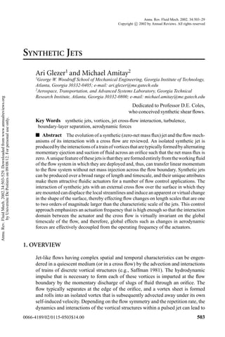
![504 GLEZER ¥ AMITAY
spatial evolution that is remarkably different from the evolution of a continuous
(conventional) jet having the same orifice and time-averaged flux of streamwise
momentum. Moreover, discrete vortical structures can also be formed within a
continuous jet by deliberate temporal modulation of its streamwise momentum
flux, which, depending on the degree and frequency of modulation, can lead to
radical modification of the unmodulated jet. For example, Lee & Reynolds (1985)
demonstrated that small changes in the azimuthal formation of successive vortex
rings in a circular jet can alter their trajectories and result in spectacular far-field
“bifurcation” or “blooming.”
“Synthetic” jet flows are similar to pulsed jets in that they are also produced by
the advection and interactions of trains of discrete vortical structures. However, a
unique feature of synthetic jets is that they are formed entirely from the working
fluid of the flow system in which they are deployed and, thus, can transfer linear
momentum to the flowsystem without net mass injection across the flowboundary.
The fluid that is necessary to synthesize the jet is typically supplied by intermittent
suction through the same flow orifice between consecutive ejections. Because the
characteristic dimensions of the ensuing jet scale with the orifice, it is possible,
in principle, to synthesize jets over a broad range of length scales [e.g., synthetic
jets having a nominal orifice dimension of 150 ¹m were fabricated using standard
silicon micromachining techniques by Coe et al. (1994, 1995), and more recently
Muller et al. (2001) reported microfabricated jet arrays].
The oscillating (time-reversed) pressure drop across an orifice that is neces-sary
to form a synthetic jet can be imposed by an acoustic field, provided that the
amplitude of the pressure oscillations is large enough to induce the time-periodic
roll-up and subsequent advection of discrete vortices. The impulse that is imparted
to each vortex has to be large enough to overcome the influence of both the orifice
image and the forces associated with the (reversed) suction flow. Ingard & Labate
(1950) used standing waves in an acoustically driven circular tube to induce an
oscillating velocity field in the vicinity of an end plate and observed the formation
of zero-net mass flux jets from opposing trains of vortex rings on both sides of
the orifice. In a later experiment, Lebedeva (1980) created a round jet with velo-cities
of up to 10 m/s, by transmitting high-amplitude sound waves through an ori-fice
placed at the end of a tube. In a related investigation, Mednikov & Novitskii
(1975) reported the formation of a jet without net mass flux and average streaming
velocities of up to 17 m/s, by inducing a low-frequency (10–100 Hz) oscillatory
velocity field at the end of a conical resonating tube driven by a piston and bellows
mechanism.
Streaming motions without mass addition can also be effected by the transmis-sion
of sound through the flow field (often referred to as acoustic streaming) or by
oscillating the boundary of a quiescent medium. Although these streaming flows
are produced without net mass flux, they are not typically accompanied by the
formation of discrete vortices that are inherent in the formation of synthetic jets by
fluid injection through an orifice. As noted by Lighthill (1978), the streaming mo-tions
induced by acoustic waves result from the dissipation of acoustic energy or
Annu. Rev. Fluid Mech. 2002.34:503-529. Downloaded from www.annualreviews.org
by Universite De Poitiers on 09/08/12. For personal use only.](data:image/gif;base64,R0lGODlhAQABAIAAAAAAAP///yH5BAEAAAAALAAAAAABAAEAAAIBRAA7)