
Recommended
More Related Content
What's hot
What's hot (20)
Similar to New microsoft power point presentation(1)
Similar to New microsoft power point presentation(1) (20)
More from HaseebAhmadChughtai
More from HaseebAhmadChughtai (19)
Recently uploaded
Recently uploaded (20)
New microsoft power point presentation(1)
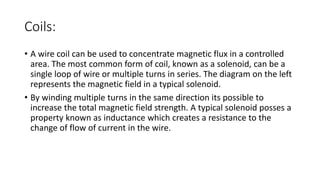
- 1. Coils: • A wire coil can be used to concentrate magnetic flux in a controlled area. The most common form of coil, known as a solenoid, can be a single loop of wire or multiple turns in series. The diagram on the left represents the magnetic field in a typical solenoid. • By winding multiple turns in the same direction its possible to increase the total magnetic field strength. A typical solenoid posses a property known as inductance which creates a resistance to the change of flow of current in the wire.
- 3. Bifilar coil • A bifilar coil is an electromagnetic coil that contains two closely spaced, parallel windings. In engineering, the word bifilar describes wire which is made of two filaments or strands. It is commonly used to denote special types of winding wire for transformers.
- 5. Description and applications: • Some bifilars have adjacent coils in which the convolutions are arranged so that the potential difference is magnified (i.e., the current flows in same parallel direction). Others are wound so that the current flows in opposite directions. The magnetic field created by one winding is therefore equal and opposite to that created by the other, resulting in a net magnetic field of zero (i.e., neutralizing any negative effects in the coil). In electrical terms, this means that the self-inductance of the coil is zero.
- 6. • A different type of bifilar coil is used in some relay windings and transformers used for a switched-mode power supply to suppress back-emf. In this case, the two wire coils are closely spaced and wound in parallel but are electrically isolated from each other. The primary coil is driven to operate the relay, and the secondary coil is short-circuited inside the case. When the current through the primary is interrupted, as happens when the relay is switched off, most of the magnetic energy is intercepted by the secondary coil which converts it to heat in its internal resistance. This is only one of several methods of absorbing the energy from the primary coil before it can damage the device (usually a vulnerable semiconductor) that drives the relay. The main disadvantage of this method is that it greatly increases the switching time of the relay.
- 7. • Bifilar coils impose an inductance in the common mode, but impose no inductance in the differential mode. Coils in such a combination are widely used to eliminate ingress or egress of common mode signals from electronic signalling circuits. This arrangement is used in transmission and reception magnetics of Ethernet cables[2] and conspicuously in the form of a ferrite bead clamped to the outside of USB, laptop power supply and HDMI cables.
- 8. Generation of voltage in Coil: • When a magnetic field penetrates a coil, the induced rotating electric field generates additive elementary voltages along the coil. Every turn in the coil receives the same voltage, we extract the power along the length of the coil, but we miss the power available in the area inside the coil !! To understand this, let’s examine the induced electric field:
- 11. • If we examine above Fig, which represents a single turn of the coil shown in Fig.1, we see that the magnetic field penetrates all of the area inside that ring. This magnetic field will be transformed to a voltage because it will drive a rotating electric field, this field is able to induce a voltage and this induced voltage will cause the current to flow due to the different of voltage between the two points A and B in Fig.1
- 12. The important, generally forgotten thing about the induced electric field, is its availability inside the coil as shown in following Fig:
- 13. • The induced electric field exists independent of the conducting loop. In other words, an induced electric field permeates all of the space within the region of the changing magnetic field, as indicated by the red field lines in above Fig. What about this field? It is wasted power. It is wasted power at point A, as well as all of the distance between the two points A and B. If we want to achieve power amplification we have to combine the magnetic field with the induced electric field in such a way as to conserve the non-conservative electric field! The induced rotating electric field will remain non-conservative but we could play with the induced voltage created by that field using a Tesla Bifilar Coil (“TBC”).
- 14. We need to extend the capacitive side of a Tesla bi-filar coil in order to benefit from the induced E field to a reasonable degree.