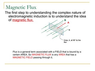
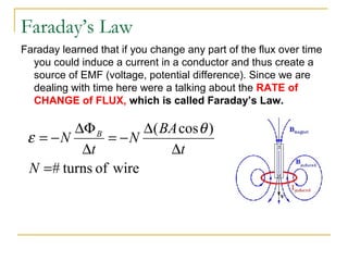
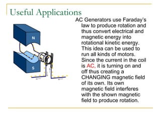
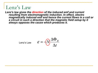
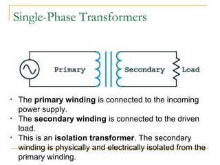
ElectroMagnetic Induction
Magnetic Induction
As the magnet moves back and forth a current is said
to be INDUCED in the wire.
Magnetic Flux
The first step to understanding the complex nature of
electromagnetic induction is to understand the idea
of magnetic flux.
Flux is a general term associated with a FIELD that is bound by a
certain AREA. So MAGNETIC FLUX is any AREA that has a
MAGNETIC FIELD passing through it.
A
B
Faraday’s Law
Faraday learned that if you change any part of the flux over time
you could induce a current in a conductor and thus create a
source of EMF (voltage, potential difference). Since we are
dealing with time here were a talking about the RATE of
CHANGE of FLUX, which is called Faraday’s Law.
wireofturns#
)cos(
=
∆
∆
−=
∆
∆Φ
−=
N
t
BA
N
t
N B θ
ε
Useful Applications
AC Generators use Faraday’s
law to produce rotation and
thus convert electrical and
magnetic energy into
rotational kinetic energy.
This idea can be used to
run all kinds of motors.
Since the current in the coil
is AC, it is turning on and
off thus creating a
CHANGING magnetic field
of its own. Its own
magnetic field interferes
with the shown magnetic
field to produce rotation.
Lenz’s Law
Lenz's law gives the direction of the induced emf and current
resulting from electromagnetic induction. In effect, electro
magnetically induced emf and hence the current flows in a coil or
a circuit in such a direction that the magnetic field setup by it
always opposes the cause which produces it.
t
N B
∆
∆Φ
−=εLenz’s Law
Inductance
 The ratio of magnetic flux to current is the
inductance.
 Inductance is measured in henry.
 1 H = 1 T m2
/ A
 More common, 1 H = 1 V / A / s
 The inductance can be derived for an ideal
solenoid.
I
L
Φ
=
l
rN
l
AN
L
22
0
2
0 πµµ
==
Induced EMF
 Faraday’s law gives the
magnitude of the induced
emf.
 Depends on rate of change
 The definition of inductance
gives a relationship between
voltage and current.
 More useful in circuits
 Inductive elements in a
circuit act like batteries.
 Stabilizes current
t
M
∆
∆Φ
−=ε
t
I
L
∆
∆
−=ε
Self Inductance
The property of the coil due to which it opposes the change of current flowing
through it is called self inductance
Suppose that we have a coil having N turns carrying a current I
That means that there is a magnetic flux through the coil
This flux can also be written as being proportional to the current
ILN B =Φ
with L being the self inductance having the same units as the mutual inductance
If the current changes, then the magnetic flux through the coil will also change,
giving rise to an induced emf in the coil
This induced emf will be such as to oppose the change in the current with its
value given by
dt
dI
L−=ε
If the current I is increasing, then
If the current I is decreasing, then
Self Inductance
There are circuit elements that behave in this manner and they are called
inductors and they are used to oppose any change in the current in the circuit
As to how they actually affect a circuit’s behavior will be discussed shortly
Self Inductance
Mutual Inductance
 The property of the coil due to
which it opposes the change of
current in neighboring coil is
called mutual inductance.
 The definition of inductance
applies to transformers.
 Mutual inductance vs self-
inductance
 Mutual inductance applies to
both windings.
AV∆
AN BN
R
t
NV M
BB
∆
∆Φ
−=∆ t
I
M
t
N M
B
∆
∆
=
∆
∆Φ
−=ε
Transformers
 A transformer is a device that changes ac electric power at
one voltage level to ac electric power at another voltage
level through the action of a magnetic field.
 There are two or more stationary electric circuits that are
coupled magnetically.
 It involves interchange of electric energy between two or
more electric systems
 Transformers provide much needed capability of changing
the voltage and current levels easily.
 They are used to step-up generator voltage to an appropriate
voltage level for power transfer.
 Stepping down the transmission voltage at various levels for
distribution and power utilization.
Transformers
Probably one of the greatest inventions of all time is the
transformer. AC Current from the primary coil moves quickly
BACK and FORTH (thus the idea of changing!) across the
secondary coil. The moving magnetic field caused by the
changing field (flux) induces a current in the secondary coil.
If the secondary coil has MORE turns
than the primary you can step up the
voltage and runs devices that would
normally need MORE voltage than
what you have coming in. We call this
a STEP UP transformer.
We can use this idea in reverse as well
to create a STEP DOWN transformer.
Single-Phase Transformers
• A transformer is a magnetically operated
machine.
• All values of a transformer are proportional
to its turns ratio.
Single-Phase Transformers
• The primary winding is connected to the incoming
power supply.
• The secondary winding is connected to the driven
load.
• This is an isolation transformer. The secondary
winding is physically and electrically isolated from the
primary winding.
Working of a transformer
1. When current in the primary coil
changes being alternating in
nature, a changing magnetic field
is produced
2. This changing magnetic field gets
associated with the secondary
through the soft iron core
3. Hence magnetic flux linked with
the secondary coil changes.
4. Which induces e.m.f. in the
secondary.
Single-Phase Transformers
• The isolation transformer greatly
reduces voltage spikes.
Single-Phase Transformers
• Each set of windings (primary and secondary) is formed from loops of wire
wrapped around the core.
• Each loop of wire is called a turn.
• The ratio of the primary and secondary voltages is determined by the ratio of
the number of turns in the primary and secondary windings.
• The volts-per-turn ratio is the same on both the primary and secondary
windings.
Constructional detail : Shell type
• Windings are wrapped around the center leg of a
laminated core.
Core type
• Windings are wrapped around two sides of a laminated square
core.
The Equivalent Circuit of a Transformer
The losses that occur in transformers have to be accounted for in any
accurate model of transformer behavior.
1. Copper (I2
R) losses. Copper losses are the resistive heating losses in the
primary and secondary windings of the transformer. They are proportional
to the square of the current in the windings.
2. Eddy current losses. Eddy current losses are resistive heating losses in
the core of the transformer. They are proportional to the square of the
voltage applied to the transformer.
3. Hysteresis losses. Hysteresis losses are associated with the
rearrangement of the magnetic domains in the core during each half-cycle.
They are a complex, nonlinear function of the voltage applied to the
transformer.
4. Leakage flux. The fluxes which escape the core and pass through only
one of the transformer windings are leakage fluxes. These escaped fluxes
produce a self-inductance in the primary and secondary coils, and the
effects of this inductance must be accounted for.
voltageload-no
voltageload-fullvoltageload-no
regulationVoltage
−
=






=
1
2
12
N
N
VV
p
s
p
s
N
N
V
V
=
Secondary voltage on no-load
V2 is a secondary terminal voltage on full load






−





=
1
2
1
2
1
2
1
regulationVoltage
N
N
V
V
N
N
V
Substitute we have
ECE 441 24
Voltage Regulation
% 100%
nl rated
rated
E V
reg per unit regulation
V
regulation per unit
−
= = − −
= − ×
Enl = no-load output voltage
Vrated = voltmeter reading at the output
terminals when the transformer is
supplying the rated apparent power
25
When the breaker is open, no current flows in Req,LS ,
jXeq,LS , or ZLOAD,LS , therefore
Vout = VLS = E’LS = Enl
26
With rated load on the secondary, E’LS = ILSZeq,LS + VLS
ILS = rated low-side current at a specified power factor
VLS = rated low-side voltage
Zeq,LS = equivalent impedance of the transformer
referred to the low-side
E’LS = no-load low-side voltage
Transformer Efficiency
Transformer efficiency is defined as (applies to motors, generators and
transformers):
%100×=
in
out
P
P
η
%100×
+
=
lossout
out
PP
P
η
Types of losses incurred in a transformer:
Copper I2
R losses
Hysteresis losses
Eddy current losses
Therefore, for a transformer, efficiency may be calculated using the following:
%100
cos
cos
x
IVPP
IV
SScoreCu
SS
θ
θ
η
++
=

Electromagnetic induction and transformer

  • 1.
  • 2.
    Magnetic Induction As themagnet moves back and forth a current is said to be INDUCED in the wire.
  • 3.
    Magnetic Flux The firststep to understanding the complex nature of electromagnetic induction is to understand the idea of magnetic flux. Flux is a general term associated with a FIELD that is bound by a certain AREA. So MAGNETIC FLUX is any AREA that has a MAGNETIC FIELD passing through it. A B
  • 4.
    Faraday’s Law Faraday learnedthat if you change any part of the flux over time you could induce a current in a conductor and thus create a source of EMF (voltage, potential difference). Since we are dealing with time here were a talking about the RATE of CHANGE of FLUX, which is called Faraday’s Law. wireofturns# )cos( = ∆ ∆ −= ∆ ∆Φ −= N t BA N t N B θ ε
  • 5.
    Useful Applications AC Generatorsuse Faraday’s law to produce rotation and thus convert electrical and magnetic energy into rotational kinetic energy. This idea can be used to run all kinds of motors. Since the current in the coil is AC, it is turning on and off thus creating a CHANGING magnetic field of its own. Its own magnetic field interferes with the shown magnetic field to produce rotation.
  • 6.
    Lenz’s Law Lenz's lawgives the direction of the induced emf and current resulting from electromagnetic induction. In effect, electro magnetically induced emf and hence the current flows in a coil or a circuit in such a direction that the magnetic field setup by it always opposes the cause which produces it. t N B ∆ ∆Φ −=εLenz’s Law
  • 7.
    Inductance  The ratioof magnetic flux to current is the inductance.  Inductance is measured in henry.  1 H = 1 T m2 / A  More common, 1 H = 1 V / A / s  The inductance can be derived for an ideal solenoid. I L Φ = l rN l AN L 22 0 2 0 πµµ ==
  • 8.
    Induced EMF  Faraday’slaw gives the magnitude of the induced emf.  Depends on rate of change  The definition of inductance gives a relationship between voltage and current.  More useful in circuits  Inductive elements in a circuit act like batteries.  Stabilizes current t M ∆ ∆Φ −=ε t I L ∆ ∆ −=ε
  • 9.
    Self Inductance The propertyof the coil due to which it opposes the change of current flowing through it is called self inductance Suppose that we have a coil having N turns carrying a current I That means that there is a magnetic flux through the coil This flux can also be written as being proportional to the current ILN B =Φ with L being the self inductance having the same units as the mutual inductance
  • 10.
    If the currentchanges, then the magnetic flux through the coil will also change, giving rise to an induced emf in the coil This induced emf will be such as to oppose the change in the current with its value given by dt dI L−=ε If the current I is increasing, then If the current I is decreasing, then Self Inductance
  • 11.
    There are circuitelements that behave in this manner and they are called inductors and they are used to oppose any change in the current in the circuit As to how they actually affect a circuit’s behavior will be discussed shortly Self Inductance
  • 12.
    Mutual Inductance  Theproperty of the coil due to which it opposes the change of current in neighboring coil is called mutual inductance.  The definition of inductance applies to transformers.  Mutual inductance vs self- inductance  Mutual inductance applies to both windings. AV∆ AN BN R t NV M BB ∆ ∆Φ −=∆ t I M t N M B ∆ ∆ = ∆ ∆Φ −=ε
  • 13.
    Transformers  A transformeris a device that changes ac electric power at one voltage level to ac electric power at another voltage level through the action of a magnetic field.  There are two or more stationary electric circuits that are coupled magnetically.  It involves interchange of electric energy between two or more electric systems  Transformers provide much needed capability of changing the voltage and current levels easily.  They are used to step-up generator voltage to an appropriate voltage level for power transfer.  Stepping down the transmission voltage at various levels for distribution and power utilization.
  • 14.
    Transformers Probably one ofthe greatest inventions of all time is the transformer. AC Current from the primary coil moves quickly BACK and FORTH (thus the idea of changing!) across the secondary coil. The moving magnetic field caused by the changing field (flux) induces a current in the secondary coil. If the secondary coil has MORE turns than the primary you can step up the voltage and runs devices that would normally need MORE voltage than what you have coming in. We call this a STEP UP transformer. We can use this idea in reverse as well to create a STEP DOWN transformer.
  • 15.
    Single-Phase Transformers • Atransformer is a magnetically operated machine. • All values of a transformer are proportional to its turns ratio.
  • 16.
    Single-Phase Transformers • Theprimary winding is connected to the incoming power supply. • The secondary winding is connected to the driven load. • This is an isolation transformer. The secondary winding is physically and electrically isolated from the primary winding.
  • 17.
    Working of atransformer 1. When current in the primary coil changes being alternating in nature, a changing magnetic field is produced 2. This changing magnetic field gets associated with the secondary through the soft iron core 3. Hence magnetic flux linked with the secondary coil changes. 4. Which induces e.m.f. in the secondary.
  • 18.
    Single-Phase Transformers • Theisolation transformer greatly reduces voltage spikes.
  • 19.
    Single-Phase Transformers • Eachset of windings (primary and secondary) is formed from loops of wire wrapped around the core. • Each loop of wire is called a turn. • The ratio of the primary and secondary voltages is determined by the ratio of the number of turns in the primary and secondary windings. • The volts-per-turn ratio is the same on both the primary and secondary windings.
  • 20.
    Constructional detail :Shell type • Windings are wrapped around the center leg of a laminated core.
  • 21.
    Core type • Windingsare wrapped around two sides of a laminated square core.
  • 22.
    The Equivalent Circuitof a Transformer The losses that occur in transformers have to be accounted for in any accurate model of transformer behavior. 1. Copper (I2 R) losses. Copper losses are the resistive heating losses in the primary and secondary windings of the transformer. They are proportional to the square of the current in the windings. 2. Eddy current losses. Eddy current losses are resistive heating losses in the core of the transformer. They are proportional to the square of the voltage applied to the transformer. 3. Hysteresis losses. Hysteresis losses are associated with the rearrangement of the magnetic domains in the core during each half-cycle. They are a complex, nonlinear function of the voltage applied to the transformer. 4. Leakage flux. The fluxes which escape the core and pass through only one of the transformer windings are leakage fluxes. These escaped fluxes produce a self-inductance in the primary and secondary coils, and the effects of this inductance must be accounted for.
  • 23.
    voltageload-no voltageload-fullvoltageload-no regulationVoltage − =       = 1 2 12 N N VV p s p s N N V V = Secondary voltage onno-load V2 is a secondary terminal voltage on full load       −      = 1 2 1 2 1 2 1 regulationVoltage N N V V N N V Substitute we have
  • 24.
    ECE 441 24 VoltageRegulation % 100% nl rated rated E V reg per unit regulation V regulation per unit − = = − − = − × Enl = no-load output voltage Vrated = voltmeter reading at the output terminals when the transformer is supplying the rated apparent power
  • 25.
    25 When the breakeris open, no current flows in Req,LS , jXeq,LS , or ZLOAD,LS , therefore Vout = VLS = E’LS = Enl
  • 26.
    26 With rated loadon the secondary, E’LS = ILSZeq,LS + VLS ILS = rated low-side current at a specified power factor VLS = rated low-side voltage Zeq,LS = equivalent impedance of the transformer referred to the low-side E’LS = no-load low-side voltage
  • 27.
    Transformer Efficiency Transformer efficiencyis defined as (applies to motors, generators and transformers): %100×= in out P P η %100× + = lossout out PP P η Types of losses incurred in a transformer: Copper I2 R losses Hysteresis losses Eddy current losses Therefore, for a transformer, efficiency may be calculated using the following: %100 cos cos x IVPP IV SScoreCu SS θ θ η ++ =