
Recommended
More Related Content
What's hot
What's hot (20)
Similar to 22564 emd 2.0 direct and bending
Similar to 22564 emd 2.0 direct and bending (20)
More from GovernmentPolytechni7
More from GovernmentPolytechni7 (14)
Recently uploaded
Recently uploaded (20)
22564 emd 2.0 direct and bending
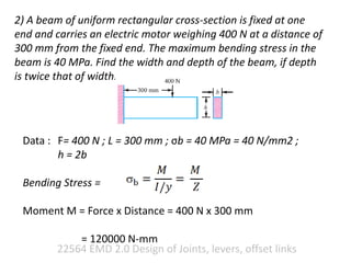
- 1. 22564 EMD 2.0 Design of Joints, levers, offset links 2) A beam of uniform rectangular cross-section is fixed at one end and carries an electric motor weighing 400 N at a distance of 300 mm from the fixed end. The maximum bending stress in the beam is 40 MPa. Find the width and depth of the beam, if depth is twice that of width. Data : F= 400 N ; L = 300 mm ; σb = 40 MPa = 40 N/mm2 ; h = 2b Bending Stress = Moment M = Force x Distance = 400 N x 300 mm = 120000 N-mm
- 2. 22564 EMD 2.0 Design of Joints, levers, offset links Section modulus of rectangular section is h = 2b Therefore b = 16.5 mm h = 2 x b = 2 x 16.5 = 33mm Neutral Axis Tensile stress Compressive stress
- 3. 22564 EMD 2.0 Direct & Bending Stresses Revision on Direct & Bending Stresses Consider a simple case shown in figure, axial force ‘F’ is subjected to tensile stress at point A and B A B F A B F e= eccentric distance Now again the Force ‘F’ is shifted with eccentric distance ‘e’, than the resultant stresses at point A and B is not only direct tensile but bending stress also.
- 4. 22564 EMD 2.0 Direct & Bending Stresses Revision on Direct & Bending Stresses Failure and stresses are shown in figure A B F e= eccentric distance Direct tension + Tension Bending Direct tension + Compression Bending
- 5. 22564 EMD 2.0 Direct & Bending Stresses Calculations of direct and bending Consider equal and opposite force ‘F’ as shown in figure A B F e= eccentric distance F F Two equal and opposite forces ‘F’ separated by distance ‘e’ creates a Moment, so equivalent figure can be A B Moment = F x e e= eccentric distance Force Total Stress = Direct Stress + Bending Stress t + b (Tensile + Tensile) t - b (Tensile + Compression)
- 6. 22564 EMD 2.0 Direct & Bending Stresses Revision on Direct & Bending Stresses Total Stress = Direct Stress + Bending Stress
- 7. 22564 EMD 2.0 Direct & Bending Stresses 1) A steel bracket is subjected to a load of 4.5 kN, as shown in Figure. Determine the required thickness of the section at A-A in order to limit the tensile stress to 70 MPa. Given Data : Force = 4.5 KN, Tensile stress = 70 Mpa
- 8. 22564 EMD 2.0 Direct & Bending Stresses t = Force / Area Area = 50 x t = 50t t = 4.5 x 1000 N / 50t = 90 / t bt = M / Z and bc = - M / Z Moment = F x e = 4.5 x 1000 x 50 = 225000 N-mm Z = b x h2 / 6 = t x 502 /6 = 416.67 t bt/c = 225000 / 416.67 t = 539.99/ t Neutral Axis t + bt t + bc
- 9. 22564 EMD 2.0 Direct & Bending Stresses t = 4.5 x 1000 N / 50t = 90 / t bt/c = 337500 / 16.67 t = 539.99 / t (Tensile + and Compression -) Maximum total stress = t + bt total = 70 Mpa = 90 / t + 539.99 / t t= 8.99 = 9mm Safe thickness = 9mm