Downloaded 224 times
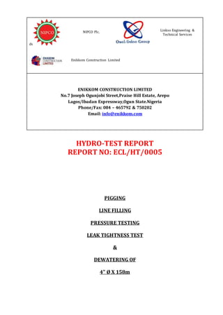
![The pump required for the operation must be rated to 1.25 times the expected backpressure. Therefore the
expected discharge pressure for the pump is approximately.
1.25 * 10.19 bar ≈ 12.74 bar
The discharge pressure rating for the pump recommended for this operation must be able to discharge at
a pressure capacity well above 12.74 bars.
The pig speed in a normal pigging operation should be within 0.5 – 1m/s if we assume a maximum pig speed
of 1m/s for this operation the equivalent flow rate would be = 8997/1 = 8997 s =2.5h
Flow rate = 649.481/2.5 = 4.32m3 /mins = 4.32*6.289= 27.01 BPM (1m3 = 6.289 Barrel)
Compressed Air Design
The pig speed should be between 2 – 8km for normal pig runs and 2 -4km/h for gauging plate runs while
using compressed air as a medium to propel the pig,
By assuming an average pig speed of 4km/h the air flow required
= (649.48 / 8,997) * 4,000 = 289 m3/h = V1
The required driving pressure when the pipeline is full of water must
Total Driving pressure required ≈ 12.74 bar = P1
Total Back pressure = 10.5 = P2
Using equation = P1*V1 = P2*V2
V2 = ( P1*V1 ) / P2 = ( 12.74 X 289 ) / 10.5
V2 = 350.65 m3/h
@ 1 m3 = 35.315 CFM
Compressed air requirement = 350 x 35.315 = 12,383ft3/h = 207 CFM
To give allowance for error in calculation 1.25 time the required air will be used = 259CFM
Therefore, a 650 CFM @ 15 Bar compressor should be adequate for the project. To achieve an 8km/hr pigging
speed a second compressor would be added while a third would be on standby for in case of breakdown.
The pig delivery time at average speed of 4-8km/hr ≈ less dawn 2 – 4 hours
1. HYDROSTATIC TEST PUMP DESIGN
The pressurizing pump required should be suitable to pressurize the test section at approximately 1 bar per
minute. The volume required to inject to give 1bar pressure can be estimated using the theoretical equation
for volume change ∆V per Pressure change ∆P for pipeline with liquid under pressures at constant
temperature, disregarding effects of air absorption or free air in the line. The Pressure-volume relationship
considering elastic strain in the pipe and Compressibility of the water is calculated thus
∆𝑉 = (
𝐷
𝐸 ∗ 𝑡
∗ ( 1 − 𝛾2) +
1
𝐵
) ∗ ∆𝑃 ∗ 𝑉
DV/DP = V * [(D/ (E * t) (1 – v²) + C]
Where,
dV = incremental volume in the same units as V
dP = incremental pressure, bar = 1
V = volume of the segment 1 = 649.481m3
V = volume of segment 2 = 200.75m3
V = Volume of the Segment 2 = 200.75m3](https://image.slidesharecdn.com/9220ad6e-2906-47a0-a50a-9b051f8f9a93-160624171217/85/Hydrotest-REPORT-FOR-4-158m-Line-8-320.jpg)
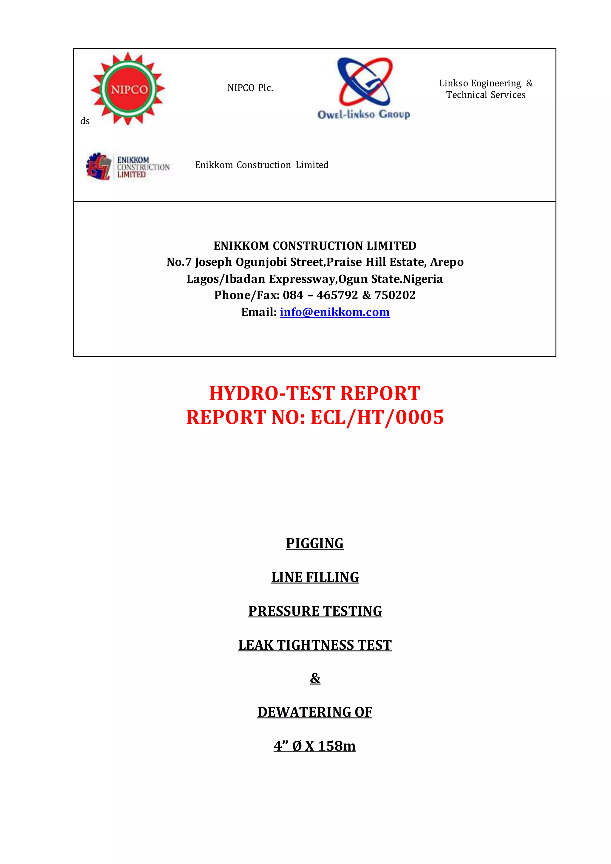
![D = Outside diameter (m), = 0.314m
E = Elastic modulus of steel pipe (psi) = 2.07 x 10*6
t = Wall Thickness of pipe (m)= 0.0095m
v = passion’s ratio steel pipe = 0.3
C = Bulk compressibility factor of liquid, per psi (the reciprocal of the bulk modulus)=
46.7 x 10*-6 bar
DV/DP = V * [(D/ (E * t) (1 – v²) + C]
DV/1 = 649.481 [0.314 / (2.07x10*6) x 0.0095) (1-0.09) + 46.7 x 10*-6]
= 649.481 [0.314/(14697)(0.91) +46.7x10*-6]
= 649.481 [0.314/13374.27)
DV = 0.02m3/min
The test pump required for this project should be capable of pumping at approximately 0.3m3 per minute at
the required test pressure.
Theoretically pressurizing the system from zero to test pressure should be directly proportional to inject
volume as calculated above, due to the pipeline profile air entrapment is expected, careful estimation of the
air entrapment would be carried out and fillingprocess would be done with high sealing pig to reduce air
entrapment in the test system.
Pipe Drying
Most of the data uses for this estimate are theoretical but in the final analysis allowance would be given for
practical field situation.
The air dew point inside the pipeline is assumed to be the same as pipe wall temperature at 15degree C
therefore, the moisture content of the air estimated on I-X graph = Xm = 12.8 g/m3.
Dry air system temperature at Outlet (-30 degrees Centigrade dew point) Xout = 0.33 g/m3
The system flow rate Vr is design for 1180 m3/h (expected compressed air capacity equivalent to what air
dryer can handle @ required departing pressure of 0.5 – 1bar pigging pressure)
N.B – The capacity can be adjusted on the field depending on field criteria and client interest)
The moisture removal capacity of the dry air system Vm =
Vm = Vr (Xm-Xout) /1000
Vm = 1180 (12.8-0.33)/1000 = 14.72 kg/h
The expected remaining water in the pipeline after successful dewatering, assuming a water film of 0.1 mm.
Remaining water = W= 3.14/4(D12-D22)*L*1000
W = 3.14/4(0.3142- 0.2952)* 8.997*1000 = kg water
=0.00908 x 8997
= 82 kg of water
The total drying time for this project T:
T = W/Vm
T = 82 / 61.85 = 5.57 hours](https://image.slidesharecdn.com/9220ad6e-2906-47a0-a50a-9b051f8f9a93-160624171217/85/Hydrotest-REPORT-FOR-4-158m-Line-9-320.jpg)


This hydro-test report summarizes the pressure testing of a 4" diameter and 158m long gas pipeline. Key details include: - Water will be used to fill, flush, and pressure test the pipeline at 147 bar, which is 150% of the design pressure of 98 bar. - Calculations are provided to determine the volume of water needed, expected back pressures, and pump requirements. Factors like elevation changes, pipe dimensions, and friction losses are accounted for. - Test equipment will be calibrated and certified. Instruments will monitor and record pressure and temperature during the test. - The pipeline will be isolated and prepared, then filled and pressure tested. Any leaks will be repaired before re-


