1. STRATEGIC BUSINESS UNIT FOR HYDRO STATIC TEST (H.T.B.U)
H.T.B.U
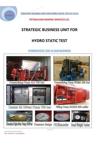
PETROLEUM MARINE SERVICES CO.
STRATEGIC BUSINESS UNIT FOR
HYDRO STATIC TEST
HYDROSTATIC TEST IS OUR BUSINESS
U
Page1
ASSISTANT GENERAL MGR
ENG. ZAKARIA EL-GHARABAWI
2. STRATEGIC BUSINESS UNIT FOR HYDRO STATIC TEST (H.T.B.U)
H.T.B.U
Abstract
U
As the company technical capabilities have grown significantly since PMS was
established in 2001, Hydro test department established at 2007 a proposal of a business
unit is made here-by to open a new market in favor of our company. A Strategic
Business Unit, SBU, can constitute a smaller part of a company with competitors different
from those of the parent company providing extra income to it. SBU can handle the
operations performed as part of the pre-commissioning of the Offshore Pipeline which
U U
include the Following activities:
x Test procedure
x Flooding,
x Cleaning,
x Gauging,
x Pressurization
x Completion of Testing
x Depressurization
x Leak test
x Dewatering
x Test Records
x RE-instatement
The technical resources, hydro test equipments, previous projects and
engineering expertise that are contained in skillful different major engineers
optimize the success of this SBU that can be extended afterwards providing a
growing income with the least expenditures.
Page2
ASSISTANT GENERAL MGR
ENG. ZAKARIA EL-GHARABAWI
3. STRATEGIC BUSINESS UNIT FOR HYDRO STATIC TEST (H.T.B.U)
H.T.B.U
Table of Contents
U
1. Introduction.............................................................................................................................................................................4
2. Human Resources .............................................................................................................................................................5
3. Hydro test Equipment.......................................................................................................................................................6
3.1 Pumps working with Engine driven.........................................................................................................6
3.2 Pumps working with Air driven...................................................................................................................7
4. Instrument…………………………………………………………………………………………………………...…….......................8
5.1 Daily Rate for Hydro Test Crew …….……………………………………......................................……...…….......….9
5.2 Daily Rate for Hydro Test Equipment…….…………………………………………...……..…...............................9
6.General preparation……………………………………………………………………………………………………...…....…10
6.1 Instruments.............................................................................................................................................................10
6.2 Cleaning, Gauging Acceptance …………………………………….….….…………………...............….10
6.3 Cleaning and Gauging Operations......................................................................................................10
6.3.1 Pig Arrangement ……………………………………………………….………………………….....………..….…10
6.3.2 Sequence ……………………………………………………………….………..….……………………………......….11
6.3.3 Stuck Pig Contingency Procedure……………..……….……………….…………………................….14
7. Pressure TEST PROCEDURE……………………………………………………………………………………….……….…...15
7.1 Introduction………………………………………….…………………………….….………………………….…..…….15
7.2 Piping System Pressure Test Sequence………………………………………………..…………........….15
7.3 Pressurization ……………………………….………………………………..………………………………….....….….15
7.4 Stabilization............................................................................................................................................................17
7.5 hold period………………………………………………………….……………………………….……………..…....….17
7.6 Acceptance/ Completion..........................................................................................................................17
7.7 Air Volume Content Calculation…………………………….………………...……………………....…..….19
7.8 Depressurization…………………………………………….……………………………………….………….....….…20
8. Risk assessment (HEALTH, SAFETY AND ENVIRONMENT)……………..…………………….. ...…..…...21
U U
8.1 MANAGEMENT OF CHANGE…………………………………………………..….……………………… ...……22
8.2 Preparation for Testing.....................................................................................................................................22
8.3 Checking Of Equipment And Instrumentation...............................................................................22
8.4 BARRIERS AND SIGNS…………………………………………………..……….….……………..………… ….....….22
9.1 Project Carried Out By Hydro test Department In A.R.E …………....………..........………...........…...23
9.2 Project Carried Out By Hydro test Department In KSA……………....……………...................….........25
10. Expected Project During 2010 / 2011 Inside Egypt................................................................................26
11. Calculation Sheets........................................................................................................................................................27
12. Pipeline Pigging General Arrangement……………………………………..………………………….....…..….29
13. Pipeline Dewatering General Arrangement………………….…………………….……………….....…...….36
14. Filling Equipment General Arrangement…………………………………………………………….. . .…....…38
15. Test Equipment General Arrangement……………………………….…………………………………..............40
16. Records & Documentation and Calibration Certificate………………..........................................…42
Page3
ASSISTANT GENERAL MGR
ENG. ZAKARIA EL-GHARABAWI
4. STRATEGIC BUSINESS UNIT FOR HYDRO STATIC TEST (H.T.B.U)
H.T.B.U
1. Introduction
U
PMS company hydrostatic test department capabilities cover two interrelating domains
pigging and hydrostatic test. This know-how encourages us to make a strategic
planning to create a business unit that has already its product to give and market that
need this service.
The engineers can perform all needed calculations for the pigging and which include
the Following activities:
x Test Requirements
U
Pressure testing shall be carried out in accordance with the requirements of specification.
Pressure Piping includes all piping designed to convey or contain process or utility fluids
Test sections documentation shall contain isometrics of piping system diagram (P&ID)
U
x Test media
For hydrostatic testing of piping system, test medium shall be used as per SAES
(Saudi Aramco engineering standards)
x Test Duration
U
Test Pressure shall be held for a minimum period of one (2) hour to enable thorough
inspection of the piping system of piping components for leaks. (As per SEAS)
x Preparation For Testing
All joints in a test shall be accessible during test and shall not be painted, insulated or
otherwise covered unit satisfactory of testing in accordance with specification.
x Test Equipments
U
Pressure required all Pressure gauges and chart recorders shall have been calibrated
current calibration certificates.
x Completion of Testing
Pressure test be considered complete when:
All defective welds, materials, flange leaks, valve gland leaks or other such
Defects have been corrected and accepted by the owner’s representative.
All documentation and test section information is complete and accepted by owner’s
Representative.
x Test Records
U
Records for piping which require that pressure be held for a specified period of time shall
Include any corrections of test Pressure due to temperature variations between the start
and finish of the test.
x Re-instatement
After successful completion of Pressure testing, the system shall be returned to a
state of commissioning readiness.
x Test Procedure
U
Page4
ASSISTANT GENERAL MGR
ENG. ZAKARIA EL-GHARABAWI
5. STRATEGIC BUSINESS UNIT FOR HYDRO STATIC TEST (H.T.B.U)
H.T.B.U
2. Human Resources
U
The following is a summary of the number of Engineers, Mechanical and Electrical
Technical of the Hydro Static Test Department.
2.1 ENGINEERS
NO. NAME JOP DESCRIPTION
1 ZAKRYIA EL-GHARABAWi ASSISTANT GENRAL MGR
2 MOHAMED HELMY EL SAYED Sector head
3 TAMER SABER GNEIDY HYDROTEST ENGINEER
4 MOSTAFA HAMED GASER HYDROTEST ENGINEER
5 MOHAMED EL-HABASHY HYDROTEST ENGINEER
6 MOHAMED KAMEL EL-SAKHAWY HYDROTEST ENGINEER
7 MOHAMED EL-SAID ALY HYDROTEST ENGINEER
8 EL-SAID SHAWKY EL-SAID HYDROTEST ENGINEER
9 MOTAZ AHMED FATHY HYDROTEST ENGINEER
10 MOHAMED ABD-ELGHANY MOHAMED HYDROTEST ENGINEER
2.2 Technical
NO. NAME JOP DESCRIPTION
1 KMAL BSHR MOHAMED SUPERVISOR
2 MOHAMED MAHMOUD SHOUKRY SUPERVISOR
3 AMR RAMDAN MOHAMED MECHANCAL Technical
4 ISLAM MOHAMED EL-NAGAR MECHANCAL Technical
5 AHMED MOHAME HEBALA Electrical Technical
6 HASSAN AHMED ABD EL-RHMAN MECHANCAL Technical
7 FATHY ABD EL-MNEM MECHANCAL Technical
8 MOHAMED ABD EL-RHEIM Electrical Technical
9 AHMED MOHAMED HUSSIEN MECHANCAL Technical
10 MAHMOUD MOHAMED DIAB MECHANCAL Technical
11 MOHAMED MORSY MOHAMED MECHANCAL Technical
12 AHMED MOHAMED ABD EL-KADER MECHANCAL Technical
13 ARFA EL-SAYED ABD ALLA MECHANCAL Technical
14 MOHAMED FAKRY HGAZY MECHANCAL Technical
15 MOHAMED ASSAM ABRHAIM Electrical Technical
Page5
ASSISTANT GENERAL MGR
ENG. ZAKARIA EL-GHARABAWI
6. STRATEGIC BUSINESS UNIT FOR HYDRO STATIC TEST (H.T.B.U)
H.T.B.U
3. HYDRO TEST Equipment
U
3.1 Pumps working with Engine driven.
U
Max.Q Max. P
Model Equip. description Serial
- l/min bar
D 300 /200-500 Holland Special Pumps BV Unit
600 m³/hr 10 bar HSP200-500 Centrifugal Pump
NT855-G6 1
Cummins engine
CPL:1381
D 300 /200-500 Holland Special Pumps BV Unit
600 m³/hr 10 bar HSP200-500 Centrifugal Pump
NT855-G6 2
Cummins engine
CPL:1381
UP to 700 Gardner Denver Pressurizing
300 l/min TX 450SB
bar Pump 3
6135HF485 John Deer Diesel Engine
Woma Pumps
U
2 X 858 40 bar 400ARP - P75 Woma - Filling Pump 40 bar
(102m³/h) 4
TAD940VE Volvo Penta Engine
2X10¹⁷ 60 bar 700ARP - P75 Woma - Filling Pump
(122m³/h) 5
TAD943VE Volvo Penta Engine
457(27m³/h) 240 bar 400ARP - P65 Woma-Pressurizing Pump
6
TAD943VE Volvo Penta Engine
509(30m³/h) 300 bar 550ARP - P70 Woma - Diesel driven
7
TAD1252VE Volvo Penta Engine
Filling Pumps
U
1200 M³/hr 13 bar 250 LNN-47 FILLING PUMP
KTA19-M3 8
Cummins engine
CPL:4150
1200 M³/hr 13 bar 250 LNN-47 FILLING PUMP
9
KTA19-M3 Cummins engine
Portable Break FILLING PUMPS
U
55 M٣/hr 1D81Z Break Tank Filling PUMP (1)
10
Hatz ENGINE
55 M٣/hr 1D81Z Break Tank Filling PUMP (2)
11
Hatz ENGINE
NFT-100-315/310 Break Tank Filling PUMP (3)
12
150 M³/hr 3 F3L 912 DEUTZ DIESEL ENGINE
NFT-100-315/310 Break Tank Filling PUMP (4)
13
150 M³/hr 3 F3L 912 DEUTZ DIESEL ENGINE
Page6
ASSISTANT GENERAL MGR
ENG. ZAKARIA EL-GHARABAWI
7. STRATEGIC BUSINESS UNIT FOR HYDRO STATIC TEST (H.T.B.U)
H.T.B.U
3.2 Pumps working with Air driven.
U
Max.air
pressure Max.Q Max. P
Model Equip. description Serial
max. flow - l/min bar
rate
U Air Driven Pumps
0.5 650 DSF-100 Haskel 1
1 350 DSF-60 Haskel 2
1000 bar
10 D14SFD - 125 Haskel 3
10 700 bar D14SFD - 315 Haskel 4
10 L/MIN D14SFD-125
Haskel
8.6 bar
700 bar 5
14 cu m/hr
10 L/MIN D14SFD-125 two pumps on one Skid
1 L/MIN 350 bar ASF-60 Haskel 6
Page7
ASSISTANT GENERAL MGR
ENG. ZAKARIA EL-GHARABAWI
8. STRATEGIC BUSINESS UNIT FOR HYDRO STATIC TEST (H.T.B.U)
H.T.B.U
4. Instrument:
U
There are many instruments using during hydrostatic test such as Dead Weight Testers,
Pressure & temp. Recorder, pressure gauges, high pressure hoses, fitting and valves
Max. P
Model Equip. description Serial
bar
Dead Weight Testers
U
AMETEK
0-10000psi Dead Weight Tester 1
D14SFD - 315
Budenberg 80HP Dead Weight Tester 2
Pressure Recorders
U
Pressure &
400 bar & 100 Cº PT-12-T 1
temp. Recorder
Pressure &
400 bar & 100 Cº PT-12-T 2
temp. Recorder
Pressure &
400 bar & 100 Cº PT-12-T 3
temp. Recorder
Pressure &
400 bar & 100 Cº PT-12-T 4
temp. Recorder
Pressure &
0 : 30 bar &100 Cº PT-12-T 5
temp. Recorder
0-250 bar Fox Boro Pressure Recorder 6
Page8
ASSISTANT GENERAL MGR
ENG. ZAKARIA EL-GHARABAWI
9. STRATEGIC BUSINESS UNIT FOR HYDRO STATIC TEST (H.T.B.U)
H.T.B.U
5. Daily Rate for Hydro Test Crew :-
U
1- LABOURS
U
Daily Rate 12 Hr/Day
ITEM DESCRIPTION QTY
($ )/ DAY
1 -: LABOURS
U
1-2 Operator(12 Hours / day ) 1 300
2-2 Engineer 1 500
5.2 Daily Rate for Hydro Test EQUIPMENT:-
U
Daily Rate 24 Hr/Day
ITEM DESCRIPTION QTY
($ )/ DAY
2-1 FILLING PUMP 600 M٣/HR 1 1600
2-2 Pressurizing pump (700 BAR) 1 1700
2-3 filter 50 micron 1 150
2-4 Chemical injection pumps 1 250
2-5 Pressure relief valve 1 30
2-6 Dead weight tester 1 100
2-7 Pressure gauge 1 10
2-8 Temperature recorder(24 HOURS) & Pressure 1 100
2-9 flow meter 1 30
Page9
ASSISTANT GENERAL MGR
ENG. ZAKARIA EL-GHARABAWI
10. STRATEGIC BUSINESS UNIT FOR HYDRO STATIC TEST (H.T.B.U)
H.T.B.U
6. General preparation
¾ Vents shall be installed at high points.
¾ Testing shall be carried out in the presence of the Owner’s Representative. Records
of all pressure tests shall be maintained.
6.1 Instruments
¾ Pressure gauges
¾ Pressure recorder
¾ Temperature recorder
¾ Dead weight tester and or,
¾ Crystal pressure gauge
6.2 Cleaning, Gauging Acceptance
The quantity of construction debris between the scrapers shall show a reducing
trend in volume during scraper recovery. Cleaning of the pipeline shall be done to
level matching the client request and specifications. Gauging of the pipeline shall
be achieved when the gauge plate is recovered without evidence of damage. If
the gauge plate is damaged, a technical evaluation and discussion shall be
undertaken onsite between Company and Contractor representatives to agree the
actions to be taken
6.3 Cleaning and Gauging Operations
6.3.1 Pig Arrangement
Pigs will be inserted in the lay down heads according the bellow schematic (lay
down head fabrication details)
LAYDOWN / SUBSEA LAUNCHER (Offshore)
. o Pig #1 - Bi-Di Cleaning / Brush pig c/o Pinger.
. o Pig #2 - Bi-Di Cleaning / Brush pig c/o Pinger
. o Pig #3- Bi-Di Magnetic pig c/o Pinger.
. o Pig #4- Bi-Di Magnetic pig c/o Pinger.
. o Pig #5 - Bi-Di Gauging pig c/o Pinger.
P a g e 10
ASSISTANT GENERAL MGR
ENG. ZAKARIA EL-GHARABAWI
11. STRATEGIC BUSINESS UNIT FOR HYDRO STATIC TEST (H.T.B.U)
H.T.B.U
6.3.2 Sequence
Upon completion of all preparation works the Pipeline will be ready for the
commencement of cleaning, gauging operations as the following :
1. Issue a Permit to start rig up the equipment on the barge deck.
2. Barriers and signs shall be erected on a safe distance (5 meters).
3. Connect suction hoses between the suction pumps and suitable sea suction level.
4. Connect discharge hoses from pump output to the collecting manifold.
5. Connect the chemical tanks through the suction hoses to the chemical pumps and
connect the delivery hoses (1/2” hoses) to the collecting manifold through ½"
needle valves for the chemicals.
6. Connect the filling hoses to the lay down head first valve (2" ball valve) for adding
the front water for lubricating and cleaning.
7. Divers shall connect and secure the filling hoses and open the 2" valve on the pig
launcher.
8. The onshore team will prepare drain hoses which shall be connected and secured
to the pig receiver drain valves to the evaporation pond.
9. After finishing all the previous preparations the onshore team and offshore team will
communicate to confirm that the system is ready to begin activities.
10. Before sending the pig train, an initial batch of clean, filtered but chemically
untreated seawater corresponding to 200 linear meters (114.239 m3) of the line
section shall be pumped in front of the first cleaning pig for lubrication and cleaning
the pipe of foreign materials.
11. After confirming that the added volume is in the pipeline by the flow meter reading.
12. Stop the filling pumps in order to connect the hoses for launching the first pig.
13. Divers to connect and secure the filling hoses and open the 6” ball valve (LBV-1) on
the pig launcher located behind the first pig.
14. Start launching the first cleaning/brush pig with Pinger (pig # 1) into the 36” pipeline
and observe the launching pressure.
15. Pumping a batch of clean, filtered and chemically treated seawater corresponding
200 linear meters of the line section (114.239 m3) shall be introduced behind the first
cleaning pig.
16. After confirming that the added volume is in the pipeline by the flow meter reading
17. Stop the filling pumps in order to attach the hoses for launching the second
cleaning brushes pig.
18. Divers to connect and secure the filling hoses and open the proponent valve
(LBV-2).
19. Start launching the second cleaning / brush pig (pig #2) into the pipeline while
observing the launching pressure.
20. Pumping a batch of clean, filtered and chemically treated seawater corresponding
to200 linear meters of the line section((114.239 m3))shall be introduced behind the
cleaning pig to launch the second cleaning brush pig.
21. After confirming that the added volume is in the pipeline by the flow meter reading
22. Stop the filling pumps in order to attach the hoses for launching the third bi-
directional magnetic pig with Pinger.
P a g e 11
ASSISTANT GENERAL MGR
ENG. ZAKARIA EL-GHARABAWI
12. STRATEGIC BUSINESS UNIT FOR HYDRO STATIC TEST (H.T.B.U)
H.T.B.U
23. Divers to connect and secure the filling hoses and open the proponent valve
(LBV-3) .
24. Start launching the third bi-directional magnetic pig (pig # 3) into the pipeline.
25. Pumping a batch of clean, filtered & treated seawater corresponding 200
linear meters of the line section((114.239 m3)) shall be introduced behind the pig to
launch the third bi-directional magnetic pig.
26. After confirming that the added volume is in the pipeline by the flow meter reading.
27. Stop the filling pumps in order to connect the hoses for launching the third bi-
directional magnetic pig.
28. Diver to connect and secure the filling hoses and open the proponent valve (LBV-4).
29. Start launching the fourth bi-directional magnetic pig (pig #4) into the pipeline.
30. Pumping a batch of clean, filtered and chemically treated seawater corresponding
200 linear meters of the line section ((114.239 m3)) shall be introduced behind the pig
to launch the fourth bidirectional magnetic pig.
31. After confirming that the added volume is in the pipeline by the flow meter reading.
32. Stop the filling pumps in order to connect the hoses for launching the fifth bi-
directional gauging pig.
33. Divers to connect and secure the filling hoses and open the proponent valve
(LBV-5).
34. The pipeline shall be gauged to ensure that pipeline is free of defects.
35. The gauging pig shall be identical to the cleaning pigs and shall include an
aluminum gauging plate; each gauging plate shall be 6 mm thick. The leading
edge shall be chamfered 45o to half the plate thickness. The gauging plate
diameter shall be 97% of, or 25 mm less than, the minimum pipeline inside diameter,
whichever is the greater.
36. The gauging pig like the all previous pigs shall be equipped with pig locator (Pinger)
since the location of stuck pigs is of paramount importance, the use of best available
pig location equipment shall be a priority.
37. A gauging plate identification number shall be stamped on the aluminum plate and
the number recorded prior to introducing the gauging pig into the pipeline.
38. Run the gauging pig equipped with gauging plate through the pipeline. Company
Site Representative will witness the removal of gauging pig from the temporary
receiving; any signs of damage shall be analyzed and reported to Company Site
Representative.
39. A deformed, bent or severely nicked plate shall not be acceptable. If any, proceed
immediately with locating any defects in the pipeline after the company site
representative judge of the level of damage to the gauging plate, this may require a
second gauge.
40. Gauging plate shall become the property of Company and shall be delivered to
Company upon completion of gauging operations.
41. Contractor shall submit to Company for approval a report on gauging pig runs and
gauging plate Condition at the completion of gauging pig run.
42. Start launching the gauging pig (pig # 5) into the pipeline.
43. Recommence pumping to launch the Gauging and the whole Pig train.
44. Inform the offshore operator on the vessel at the pipeline end that the Pig train (5 bi-
directional pigs) has been launched.
P a g e 12
ASSISTANT GENERAL MGR
ENG. ZAKARIA EL-GHARABAWI
13. STRATEGIC BUSINESS UNIT FOR HYDRO STATIC TEST (H.T.B.U)
H.T.B.U
45. The gauging pig will be sent using a volume equal to 104% of the total pipeline fill
(including the patches between the pigs ), the last 100% of this flooding water will be
chemically treated water.
46. Continue to flood the pipe section until the 5th pig has been received onshore in
the receiver.
47. The pigging operation will be carried out in controlled manner to maintain the pig
train speed between minimum 0.3 m/s and not exceeding 2 m/s.
48. Communication between the offshore team and the onshore team shall be
continued during the whole operation.
49. When the seawater stopped to expel from the drain hose on receiving head and
minor pressure rise shall be indicated on the pressure gauge on the barge so the
onshore team announce to the offshore team that one or more of the pigs have
been arrived.
50. Pumping shall be continued, in order to preserve a constant a pig speed so the
onshore team shall check the arrival by using the Pinger receiver.
51. Log the arrival time of Pigs, Operator to check the actual / expected arrival time.
52. Then shut down the filling and suction pumps.
53. Disconnect filling hose from filling inlet valve, close and plug the inlet valve
54. Log the following records at (30) minute intervals:
54.1. Pipeline pressure during the whole pigging operations
54.2. Flow rate (Flow meter readings)
54.3. Cumulative volume ( pig Position )
54.4. Filling water temperature
54.5. The Pigs position and velocity will be computed from the flow meter readings.
All the recorded data will be logged in the reports attached in the appendices and
shall be signed by the client and delivered after finishing the operations.
55. After confirming the arrival of all pigs, The pigs recovery will be done mechanically
and no wash out during the recovery as following steps and attached drawings :
55.1. Open the receiving head gate to recover the Pigs.
55.2. Pulling method (such as Air tugger or other available method on site, Etc.)
to pull the pigs out of the receiver.
55.3. Holder on support.
55.4. A wire or rope will be attached to the pig pad eye and start pulling out
and receiving it on the holder which shall be positioned on a support to be
at the same level of the pulling line.
55.5. The recovery of the pigs shall photo recorded and checked by the
company site representative to ensure that no broken pieces or missing
parts.
55.6. The collected dirt in front of the last pigs recovered shall be checked and
analyzed to check the level of the cleanliness, acceptance which shall be
as per company specifications.
55.7. Extra care will be taken on removing the Gauging Pig to ensure no damage
occurs to the gauging plate.
P a g e 13
ASSISTANT GENERAL MGR
ENG. ZAKARIA EL-GHARABAWI
14. STRATEGIC BUSINESS UNIT FOR HYDRO STATIC TEST (H.T.B.U)
H.T.B.U
56. Contractor and Company onshore Site Representatives will witness the removal
of gauging pig from the temporary receiving head; any signs of damage shall be
analyzed and reported to Company Site Representative.
57. After successful cleaning / gauging operations and being accepted by
Company Site Representative, retrieve the filling system and prepare the pipeline
for hydrostatic testing operations.
6.3.3 Stuck Pig Contingency Procedure
1-Should any of the pigs become stuck or passing along the pipeline, pigging
operations shall be stopped per client request and locate the blocked pig(s)
and/or line damage and report the results to Company Site Representative.
2-Contractor shall carry out any necessary remedial action then the pipeline shall
be flooded, cleaned and re-gauged which shall be started from the onshore
side.
The following plan will be followed to define the cause of obstruction:
3.1 A diving support vessel will be deployed over the pigs’ locations and divers
will confirm the position subsea using diver held Pinger receiver and visually
inspect the pipe for any damage.
3.2 If any damage is observed, remedial action will be carried out.
3.3 Mobilizing the necessary equipment to the shore or preparing the offshore
to launch new pigs for cleaning and re-gauging.
3.4 If no damage found, trials to push out the stuck pig(s) will be done by increasing the
water flow and monitor the result by increasing the volume behind the pig which will
increase the back pressure which shall be enough to be used to move out the stuck pig
from its position (Water Hammering Techniques).
3.5 Otherwise, a Foam pig shall be launched from the onshore temporary pig
receiver at the pipeline start up point using compressed air.
3.6 Stuck Pig and /or pigs should be pushed back to the lay down pig
launching head at KP28.
4-Gauge plate will be inspected in presence of Company Site Representative.
5-If gauge plate is damaged, a new pigging operation will be carried out with a new
gauging plate
P a g e 14
ASSISTANT GENERAL MGR
ENG. ZAKARIA EL-GHARABAWI
15. STRATEGIC BUSINESS UNIT FOR HYDRO STATIC TEST (H.T.B.U)
H.T.B.U
7. RESSURE TEST PROCEDURE
7.1 Introduction
¾ The hydro testing shall be performed for the piping system loops. The testing head
shall be located as injection Point (lowest point at). The vents located at highest
points as mentioned before in the description.
¾ The test pressure (TP) shall be according to the table of line information.
¾ PMS shall submit pressurization / temperature charts prepared for the test to
Company Site Representative for approval before commencing the test.
¾ Flooding and venting for purpose of testing shall be performed in a manner that
minimizes air inclusion in the piping system.
¾ All fittings, hoses and valves used during testing shall be capable for pressurization
exceeding the maximum test pressure and the pressurizing pump shall be capable
of testing. Pressure range exceeding test pressure by at least 20%.
7.2 Piping System Pressure Test Sequence
Upon completion of all preparation works, securing the plant site so the piping system
will be ready for the commencement of pressure testing operations as the following:
Open the valves on testing head.
¾ Open the venting points to allow water / air expel until the system topping up.
¾ Start-up the filling pumps and begins topping up the system from testing head whilst
venting.
¾ Allow water to expel from the venting points until no further entrapped air is
observed (complete stream of water), and close the vent points and then stop
pumping.
¾ Inform the Company Site Representative that system is topped up and ready for the
pressure testing operation and then obtain permission to commence.
¾ Thereafter open instruments valve and start the system pressurization.
7.3 Pressurization
Pressurization shall be carried out in the presence of the Company Site Representative.
The pressure rise will be gradual and under control to allow time for material to strain
and for personal to check for leaks.
P a g e 15
ASSISTANT GENERAL MGR
ENG. ZAKARIA EL-GHARABAWI
16. STRATEGIC BUSINESS UNIT FOR HYDRO STATIC TEST (H.T.B.U)
H.T.B.U
7.3.1 Pressure test using Sea Water as a test medium:
¾ Pressurize up to 25% at (1) bar/minute, and stop to carry out air inclusion test.
¾ Pressurize up to 50% of test pressure at (1) bar/minute, and stabilize for (10)
minute and check any visual leak
¾ Pressurize up to 70% of test pressure at (1) bar/minute, and stabilize for (10)
minutes check any visual leak.
¾ Pressurize up to 90% of test pressure at (1) bar/minute, and stabilize for (10)
minutes check any visual leak.
¾ Pressurize up to 100% of test pressure at (0.1) bar/minute, stop and
commence stabilization period.
note: while operation is RUNNING, if there is any leak appears:-
¾ Stop pressurizing pump immediately, Depressurize the system to
atmospheric pressure.
¾ Looking for any leakage from testing connections by visual detection
and elimination.
¾ Inform the Company Site Representative that the leak is over and
ready to commence.
7.4 Stabilization :-
¾ When the test pressure is attained, the pressurizing pump will be
stopped. The system is allowed to stabilize for a period of not less than
(30) minutes.
7.5 hold period :-
¾ 1-The test pressure will be held without additional pumping for a
minimum period of (24) hours.
¾ During the test period, the following parameters shall be recorded:-
¾ Time
¾ Pipeline Pressure
¾ Ambient temperature (every ½ hour)
¾ Water pressure and temperature (continuously and every ½ hour)
¾ 2- The pressure and temperature recorders shall be started with the
charts in a real time orientation for continuous record throughout the
test, from commencement of pressurization to final accepts of test.
P a g e 16
ASSISTANT GENERAL MGR
ENG. ZAKARIA EL-GHARABAWI
17. STRATEGIC BUSINESS UNIT FOR HYDRO STATIC TEST (H.T.B.U)
H.T.B.U
7.6 Acceptance/ Completion
¾ Upon completion of the pipeline hydrostatic testing and being
accepted by Company Site
¾ Representative, in written approval.
¾ 1- At any certain time during the hold period if any pressure drop
below the hydrostatic test
¾ pressure noticed, the reduction in pressure shall be accounted for by
temperature fluctuations
¾ As per allowed pressure drop tolerances. Calculation sheet and graphs
for estimate pressure
¾ Change due to the temperature change attached in the appendices.
¾ 2- The pressure test shall be considered successful when the pressure
has been held for 24 hours
¾ with no signs of leakage and the pressure variation is within ± 0.2% of
the test pressure in
¾ Accordance with DNV-OS-F101 section 9 O 500. (Kindly refer to the
calculation sheet
¾ attached in the appendices)
¾ 3- The pressure variation due to temperature variation formula is as
follow:
W d –
P a g e 17
ASSISTANT GENERAL MGR
ENG. ZAKARIA EL-GHARABAWI
18. STRATEGIC BUSINESS UNIT FOR HYDRO STATIC TEST (H.T.B.U)
H.T.B.U
P a g e 18
ASSISTANT GENERAL MGR
ENG. ZAKARIA EL-GHARABAWI
19. STRATEGIC BUSINESS UNIT FOR HYDRO STATIC TEST (H.T.B.U)
H.T.B.U
7.7 Air Volume Content Calculation
¾ The air content of the filled line shall be determined by recording the
quantity of water(V1) that was
¾ used to generate a pressure rise of (P1).then measured quantity (V1)
should be compared to the
¾ theoretical one (VP)
¾ The theoretical quantity of water which used to generate the pressure
rise shall be according to the
¾ following formula: (Kindly refer to the calculation sheet attached in the
appendices)
sW s / W
Where :-
P a g e 19
ASSISTANT GENERAL MGR
ENG. ZAKARIA EL-GHARABAWI
20. STRATEGIC BUSINESS UNIT FOR HYDRO STATIC TEST (H.T.B.U)
H.T.B.U
7.8 Depressurization:-
¾ Start to depressurize the line after the data and information from the
test has been approved.
¾ Depressurization of the pipeline shall be performed as a controlled
operation, normally at a rate 1 Bar / Minute until the pressure has been
reduced to 40% of the test pressure. Then depressurization should
continue at a rate of less than 2 bars per minute to a hydrostatic head
, and will be recorded.
After that, after reaching to zero bars, close all valves on testing and venting
head, and then disconnect all hoses, equipment and instruments.
P a g e 20
ASSISTANT GENERAL MGR
ENG. ZAKARIA EL-GHARABAWI
21. STRATEGIC BUSINESS UNIT FOR HYDRO STATIC TEST (H.T.B.U)
H.T.B.U
8. HEALTH, SAFETY AND ENVIRONMENT
The safety of personnel is of importance during all operations and related
activities. All safety precautions shall be taken to minimize the risk to all Personnel
involved. It is the responsibility of the supervisor as well as the individual to ensure that
the following points are considered prior to commencement of activities:
¾ Ensure that all equipment is in good condition and suitably maintained.
¾ Ensure good housekeeping to avoid unnecessary trip hazards.
¾ Check if personnel require any further training prior to commencing activities.
¾ Ensure all personnel have the correct PPE.
¾ Check if manual handling is necessary or can be avoided.
¾ Ensure installation of any screens or barriers for the protection of others if
Necessary.
¾ Ensure availability and accessibility of first aid facilities.
¾ Ensure all equipment is certified in accordance with Company, Contractor and
PMS HSE requirements.
¾ Ensure availability of data sheets on site.
¾ Provide checklist procedure covering all operational activities.
¾ Ensure attendance of all relevant personnel at the toolbox talk prior to the
commencement of work and at the beginning of each shift.
¾ Ensure completion and availability of work permit.
¾ Prior to any system being worked on (pressurized), all non-essential personnel will
be removed from the cordoned area.
¾ Once the system is under pressure, only authorized personnel will be allowed to
enter the cordoned area for flange inspections and such like.
A copy of the risk assessment shall be attached to the permit to work and discussed
at the beginning of each shift to ensure personnel are aware of risks and limitations.
P a g e 21
ASSISTANT GENERAL MGR
ENG. ZAKARIA EL-GHARABAWI
22. STRATEGIC BUSINESS UNIT FOR HYDRO STATIC TEST (H.T.B.U)
H.T.B.U
8.1 MANAGEMENT OF CHANGE :-
¾ Any work arising that requires a change to organization, personnel, systems,
process /method, procedures, products, materials or laws and regulations shall be
subject to the process of re-evaluation and approval in strict accordance with the
relevant project specifications / HSE requirements. Any change resulting from the
above shall be incorporated in the procedures and risk assessed accordingly.
8.2 Preparation For Testing :-
¾ Prior to arrival at the work site(s) all PMS personnel shall attend the Company HSE
induction course.
¾ Once on site the PMS Representative shall ensure that all personnel comply with
requirements of Company regarding reporting, safety and attendance at any
briefing and meetings where their presence is required.
¾ Upon completion of the relevant induction training, the personnel will be post at
plant sites to keep the test area clear of all people not concerned with the test
and start to rig up the equipments.
¾ Check the isolation of the equipments not adequate for test pressure (according
to the PID and the description of equipment rig up for each loop).
¾ There are an additional bleeding and isolating valves
¾ Test manifold to be with pressure test diagram.
8.3 CHECKING OF EQUIPMENT AND INSTRUMENTATION
¾ The PMS Representative shall be responsible for ensuring that the equipment and
instrumentation that is delivered to the site is in accordance with the equipment
and instrument lists.
¾ PMS Representative shall also check and ensure that all relevant equipment have
satisfactory Certification.
¾ Instrumentation will be calibrated by a certified company.
8.4 BARRIERS AND SIGNS
¾ The PMS Representative shall agree with the Site Safety Officer the positions of a
safe boundary for each operation and the positions in which signs are to be
placed. Barrier tape / bunting and warning signs shall mark the agreed boundary.
No work other than that controlled by the PMS Representative shall be allowed within
the define boundary during operations for which PMS is responsible. Entry of
unauthorized personnel shall be prohibited. PMS personnel shall patrol and monitor the
cordoned boundary during operations to prevent the entry of unauthorized personnel
and the commencement of other work.
P a g e 22
ASSISTANT GENERAL MGR
ENG. ZAKARIA EL-GHARABAWI
23. STRATEGIC BUSINESS UNIT FOR HYDRO STATIC TEST (H.T.B.U)
H.T.B.U
9. Project Carried Out By Hydro test Department In A.R.E
Duration Marine unit/barge Equipment Project name S/N
1-FILLING PUMP 40 BAR
2- FILLING PUMP 60 BAR GUPCO
3- PRESSURIZING PUMP 300 BAR TART
FROM
4- AIR DRIVEN PUMP (HASKEL) 350BARC/W BEACH PALL PIPE 1
1/7/2007 P.M.S 11
PRESSURE/ TEMPERATURE RECORDER 20
TO +
DEAD WIEGHT TESTER PRESSURE GUAGE 40KM
1/9/2007 O NSHORE SIT
5- FILLING PUMP CONTAINER
1-FILLING PUMP 40 BAR
2- FILLING PUMP 60 BAR
3- PRESSURIZING PUMP 300 BAR
DURING
4- AIR DRIVEN PUMP (HASKEL) 350BARC/W RASHPETCO
JANUARY PMS MAYO 2
PRESSURE/ TEMPERATURE RECORDER P1
2008
DEAD WIEGHT TESTER PRESSURE GUAGE
1-FILLING PUMP 40 BAR
2- FILLING PUMP 60 BAR
PORT SAID 3- PRESSURIZING PUMP 300 BAR
FROM JUNE ON SHORE 4- AIR DRIVEN PUMP (HASKEL) PETROBEL
TO OCTOBER + 350BARC/W DENNIS 3
2008 PMS Mayo PRESSURE/ TEMPERATURE RECORDER PIPES
DEAD WIEGHT TESTER PRESSURE GUAGE
1-FILLING PUMP 40 BAR
2- FILLING PUMP 60 BAR
3- PRESSURIZING PUMP 240 BAR
FROM MAY PMS MAYO 4- AIR DRIVEN PUMP (HASKEL) RASHPETCO
TO JUNE 350BARC/W P2 4
2008 PRESSURE/ TEMPERATURE RECORDER
DEAD WIEGHT TESTER PRESSURE GUAGE
1- AIR DRIVEN PUMP (HASKEL)
300BARC/W
DURING PRESSURE/ T EMPERATURE RECORDER GUPCO
JANUARY TIM BARGE DEAD WIEGHT TESTER PRESSURE GUAGE MORGAN 36 5
2008 P/F
P a g e 23
ASSISTANT GENERAL MGR
ENG. ZAKARIA EL-GHARABAWI
24. STRATEGIC BUSINESS UNIT FOR HYDRO STATIC TEST (H.T.B.U)
H.T.B.U
9.1 Project Carried Out By Hydro test Department In A.R.E
Duration Marine unit/barge Equipment Project name S/N
1-FILLING PUMP 40 BAR
2- FILLING PUMP 60 BAR
3- PRESSURIZING PUMP 300 BAR
FROM
PMS 11 4- AIR DRIVEN PUMP (HASKEL) NORTH SINA
JANUARY
PMS 17 350BARC/W PETROLUEM
TO JUNE
PMS MAYO PRESSURE/ TEMPERATURE RECORDER COMPANY 6
2008
DEAD WIEGHT TESTER PRESSURE GUAGE
5- FILLING PUMP CONTAINER
FROM 1- AIR DRIVEN PUMP (HASKEL)
JANUARY 350 BAR C/W
TO APRIL C – MASTER GUPCO
PRESSURE/ TEMPERATURE RECORDER
2008 SAQQARA 7
DEAD WIEGHT TESTER PRESSURE GUAGE
1- AIR DRIVEN PUMP (HASKEL)
350 BAR C/W GENERAL
DURING
PRESSURE/ TEMPERATURE RECORDER PETROLUEM
OCTOBER 8
PMS 17 DEAD WIEGHT TESTER PRESSURE GUAGE COMPANY
2008
PIPE 11
1- AIR DRIVEN PUMP (HASKEL)
FROM MARCH 350 BAR C/W PETROBEL
2008 TO PRESSURE/ TEMPERATURE RECORDER 9
MACOBRE 12 PIPE 6 8
JANUARY 2009 DEAD WIEGHT TESTER PRESSURE GUAGE
GENERAL
DURING 1- TEST PUMP 25 BAR C/W PETROLUEM
JULLY 2-PRESSUR GAUGE PRESSURE COMPANY
2008 PMS 17 TEMPERATURE RECORDER AMER 5 10
P/F
1- AIR DRIVEN PUMP (HASKEL)
AHMED
FROM 350BARC/W
JACK UP
OCTOBER 2-PRESSURE/ TEMPERATURE RECORDER GUPCO
BARGE
TO DEAD WIEGHT TESTER PRESSURE GUAGE SAQQARA 11
NOVEMBER2008 3- FILLING PUMP CONTAINER
P a g e 24
ASSISTANT GENERAL MGR
ENG. ZAKARIA EL-GHARABAWI
25. STRATEGIC BUSINESS UNIT FOR HYDRO STATIC TEST (H.T.B.U)
H.T.B.U
9.2 Project Carried Out By Hydro test Department In KSA
Duration Marine unit/barge Equipment Project name S/N
1-FILLING PUMP 40 BAR
2- FILLING PUMP 60 BAR
3- PRESSURIZING PUMP 300 BAR
FROM 4- AIR DRIVEN PUMP (HASKEL) 350BARC/W
NOVEMBER2008 PRESSURE/ TEMPERATURE RECORDER ARAMCO
1
TILL NOW DEAD WIEGHT TESTER
PRESSURE GUAGE
5- FILLING PUMP CONTAINER
1-FILLING PUMP 40 BAR
2- FILLING PUMP 60 BAR
3- PRESSURIZING PUMP 300 BAR
4- AIR DRIVEN PUMP (HASKEL) 350BARC/W KHAFJI JOIN
FROM JANUARY
PRESSURE/ TEMPERATURE RECORDER VENTURE
2009 TILL NOW 2
DEAD WIEGHT TESTER KJO
PRESSURE GUAGE
5- FILLING PUMP CONTAINER
FROM DECGMBER
Subcontractor SAQA SAbESCO
2008 TO P.M.S 11 PIP6 24 3
PMS SUPERVISION ONLY
JANUARY 2009
P a g e 25
ASSISTANT GENERAL MGR
ENG. ZAKARIA EL-GHARABAWI
26. STRATEGIC BUSINESS UNIT FOR HYDRO STATIC TEST (H.T.B.U)
H.T.B.U
ARAMCO PROJECT PIPE LINES CURRY OUT BY PMS HYDROSTATIC TEST CREW DURING 2009:
1- ARAMCO ( KSA ) BERRI OIL FIELD
Test
Code Pipe Line Location Diameter Length Duration
Pressure
1 Berri TP-3 to Berri 194 24 inch 5.58 KM 2009 4200 PSI
2 Berri 194 to Berri TP1 24 inch 9.57 KM 2009 4200 PSI
3 Berri 142 to Berri 119 12 inch 3.6 KM 2009 4200 PSI
4 Berri DS203 to valve skid 12 inch 3.47 KM 2009 4200 PSI
2- ARAMCO ( KSA ) SAFANIYA OIL FIELD
Test
Code Pipe Line Location Diameter Length Duration
Pressure
1 SFNY 900 to SFNY TP-17 24 inch 8.6 KM 2009 4200 PSI
2 SFNY 666 to SFNY TP-17 24 inch 11 KM 2009 4200 PSI
P a g e 26
ASSISTANT GENERAL MGR
ENG. ZAKARIA EL-GHARABAWI
27. STRATEGIC BUSINESS UNIT FOR HYDRO STATIC TEST (H.T.B.U)
H.T.B.U
ARAMCO PROJECT PIPE LINES CURRY OUT BY PMS HYDROSTATIC TEST CREW DURING FROM
27/3/2010 TO 12/9/2010 :
1-ARAMCO ( KSA ) ZULUF OIL FIELD
Test
Code Pipe Line Location Diameter Length Duration
Pressure
1 Zulf TP-5 to Zulf 360 16 inch 5.6 KM 2010 4200 PSI
2 Zulf TP-3 to Zulf 282 16 inch 5.6 KM 2010 4200 PSI
3 Zulf TP-6 to Zulf 51 16 inch 1.2 KM 2010 4200 PSI
4 Zulf TP-6 to Zulf 380 16 inch 4.9 KM 2010 4200 PSI
5 Zulf TP-6 to Zulf 390 16 inch 4.9 KM 2010 4200 PSI
6 Zulf TP-4 to Zulf TP-7 30 inch 5.6 KM 2010 3800 PSI
2- ARAMCO ( KSA ) MARJAN OIL FIELD
Test
Code Pipe Line Location Diameter Length Duration
Pressure
1 MAHRA 24 to MRJN TP-8 16 inch 800 M 2010 4200 PSI
2 MRJN TP-6 to MRJN 105 16 inch 3.1 KM 2010 4200 PSI
3 MRJN TP-5 to MRJN 255 16 inch 2.3 KM 2010 4200 PSI
4 MRJN TP-4 to MRJN 240 16 inch 8.4 KM 2010 4200 PSI
P a g e 27
ASSISTANT GENERAL MGR
ENG. ZAKARIA EL-GHARABAWI
28. STRATEGIC BUSINESS UNIT FOR HYDRO STATIC TEST (H.T.B.U)
H.T.B.U
P a g e 28
ASSISTANT GENERAL MGR
ENG. ZAKARIA EL-GHARABAWI
29. STRATEGIC BUSINESS UNIT FOR HYDRO STATIC TEST (H.T.B.U)
H.T.B.U
P a g e 29
ASSISTANT GENERAL MGR
ENG. ZAKARIA EL-GHARABAWI
30. STRATEGIC BUSINESS UNIT FOR HYDRO STATIC TEST (H.T.B.U)
H.T.B.U
P a g e 30
ASSISTANT GENERAL MGR
ENG. ZAKARIA EL-GHARABAWI
31. STRATEGIC BUSINESS UNIT FOR HYDRO STATIC TEST (H.T.B.U)
H.T.B.U
P a g e 31
ASSISTANT GENERAL MGR
ENG. ZAKARIA EL-GHARABAWI
32. STRATEGIC BUSINESS UNIT FOR HYDRO STATIC TEST (H.T.B.U)
H.T.B.U
Al-KHAFJI PROJECT PIPE LINES CURRY OUT BY PMS HYDROSTATIC TEST CREW
DURING FROM 01/01/2010 TO 23/9/2010 :
x PMS Crew Carry Out Hydrostatic Test Required For All Loops On
Al-KHAFJI Platforms (Y2-B ) ( Y4 ) ( Y1-B ) AND ( Y3 )With different Pressure
Test ( Form 27 Bar To 70 Bar )
x PMS Hydro Test Engineering Supervision of Per Commissioning Of The
Pipe lines Detailed Below for Hydrostatic test Carry Out By B.J Co.
P a g e 32
ASSISTANT GENERAL MGR
ENG. ZAKARIA EL-GHARABAWI
33. STRATEGIC BUSINESS UNIT FOR HYDRO STATIC TEST (H.T.B.U)
H.T.B.U
10. Expected Project During 2010 / 2011 Inside Egypt
Projects Expected in Egypt During 2010/2011
Expected Start
No Project Name Expected days Marine Unit Specification Notes
days
Denise - B- 2010 Leak Test Press.=157 bar
1 15 From 31/10/2010 Mayo
Test 16 16 6.5 Km
From 5/12/2010 To T.P.=35 BAR
2 Petrobel 10 7 PMS 17 Cost Plus
22/2/2010 2.56Km
From 5/12/2010 To T.P.=35 BAR
3 Petrobel 14 7 PMS 17 Cost Plus
22/2/2010 0.6Km
From 5/12/2010 To T.P.=35 BAR
4 Petrobel 18 7 PMS 17 Cost Plus
22/2/2010 1.1Km
Test Press.=160 bar
5 ABU QIR Petroleum 12 10 /9/2010
P/L 12 4.7 Km
6 ABU QIR Petroleum 10 25 P/L 10 17Km
Al Amal Petroleum
7 16 P/L 24 16.34km
Company 24
Al Amal Petroleum
8 10 P/L 4 16.34km
Company 4
Al Amal Petroleum
9 7 P/L 8 1.232km
Company 8
10
P a g e 33
ASSISTANT GENERAL MGR
ENG. ZAKARIA EL-GHARABAWI
34. STRATEGIC BUSINESS UNIT FOR HYDRO STATIC TEST (H.T.B.U)
H.T.B.U
11.Calculation sheets
P a g e 34
ASSISTANT GENERAL MGR
ENG. ZAKARIA EL-GHARABAWI
35. STRATEGIC BUSINESS UNIT FOR HYDRO STATIC TEST (H.T.B.U)
H.T.B.U
11.1Calculation sheets Included Items:
x Main Pipe Line Data
x Flow Measurement
x Volume To Pressurize
The incremental volume of water added, divided by the
P
incremental change in pressure is represented by V
.
P
x Temperature and Pressure Relationship By T
x Air volume of Content
x Dewatering Operation
P a g e 35
ASSISTANT GENERAL MGR
ENG. ZAKARIA EL-GHARABAWI
36. STRATEGIC BUSINESS UNIT FOR HYDRO STATIC TEST (H.T.B.U)
H.T.B.U
12.Pipeline pigging
General Arrangement
P a g e 36
ASSISTANT GENERAL MGR
ENG. ZAKARIA EL-GHARABAWI
37. STRATEGIC BUSINESS UNIT FOR HYDRO STATIC TEST (H.T.B.U)
H.T.B.U
P a g e 37
ASSISTANT GENERAL MGR
ENG. ZAKARIA EL-GHARABAWI
38. STRATEGIC BUSINESS UNIT FOR HYDRO STATIC TEST (H.T.B.U)
H.T.B.U
P a g e 38
ASSISTANT GENERAL MGR
ENG. ZAKARIA EL-GHARABAWI
39. STRATEGIC BUSINESS UNIT FOR HYDRO STATIC TEST (H.T.B.U)
H.T.B.U
P a g e 39
ASSISTANT GENERAL MGR
ENG. ZAKARIA EL-GHARABAWI
40. STRATEGIC BUSINESS UNIT FOR HYDRO STATIC TEST (H.T.B.U)
H.T.B.U
P a g e 40
ASSISTANT GENERAL MGR
ENG. ZAKARIA EL-GHARABAWI
41. STRATEGIC BUSINESS UNIT FOR HYDRO STATIC TEST (H.T.B.U)
H.T.B.U
P a g e 41
ASSISTANT GENERAL MGR
ENG. ZAKARIA EL-GHARABAWI
42. STRATEGIC BUSINESS UNIT FOR HYDRO STATIC TEST (H.T.B.U)
H.T.B.U
P a g e 42
ASSISTANT GENERAL MGR
ENG. ZAKARIA EL-GHARABAWI
43. STRATEGIC BUSINESS UNIT FOR HYDRO STATIC TEST (H.T.B.U)
H.T.B.U
13. Pipeline Dewatering
General Arrangement
P a g e 43
ASSISTANT GENERAL MGR
ENG. ZAKARIA EL-GHARABAWI
44. STRATEGIC BUSINESS UNIT FOR HYDRO STATIC TEST (H.T.B.U)
H.T.B.U
P a g e 44
ASSISTANT GENERAL MGR
ENG. ZAKARIA EL-GHARABAWI
45. STRATEGIC BUSINESS UNIT FOR HYDRO STATIC TEST (H.T.B.U)
H.T.B.U
14.Filling Equipment
General Arrangement
P a g e 45
ASSISTANT GENERAL MGR
ENG. ZAKARIA EL-GHARABAWI
46. STRATEGIC BUSINESS UNIT FOR HYDRO STATIC TEST (H.T.B.U)
H.T.B.U
P a g e 46
ASSISTANT GENERAL MGR
ENG. ZAKARIA EL-GHARABAWI
47. STRATEGIC BUSINESS UNIT FOR HYDRO STATIC TEST (H.T.B.U)
H.T.B.U
15.Test Equipment
General Arrangement
P a g e 47
ASSISTANT GENERAL MGR
ENG. ZAKARIA EL-GHARABAWI
48. STRATEGIC BUSINESS UNIT FOR HYDRO STATIC TEST (H.T.B.U)
H.T.B.U
P a g e 48
ASSISTANT GENERAL MGR
ENG. ZAKARIA EL-GHARABAWI
49. STRATEGIC BUSINESS UNIT FOR HYDRO STATIC TEST (H.T.B.U)
H.T.B.U
16.Records and
Documentation
P a g e 49
ASSISTANT GENERAL MGR
ENG. ZAKARIA EL-GHARABAWI
50. STRATEGIC BUSINESS UNIT FOR HYDRO STATIC TEST (H.T.B.U)
H.T.B.U
P a g e 50
ASSISTANT GENERAL MGR
ENG. ZAKARIA EL-GHARABAWI
51. STRATEGIC BUSINESS UNIT FOR HYDRO STATIC TEST (H.T.B.U)
H.T.B.U
P a g e 51
ASSISTANT GENERAL MGR
ENG. ZAKARIA EL-GHARABAWI
52. STRATEGIC BUSINESS UNIT FOR HYDRO STATIC TEST (H.T.B.U)
H.T.B.U
P a g e 52
ASSISTANT GENERAL MGR
ENG. ZAKARIA EL-GHARABAWI
53. STRATEGIC BUSINESS UNIT FOR HYDRO STATIC TEST (H.T.B.U)
H.T.B.U
P a g e 53
ASSISTANT GENERAL MGR
ENG. ZAKARIA EL-GHARABAWI
54. STRATEGIC BUSINESS UNIT FOR HYDRO STATIC TEST (H.T.B.U)
H.T.B.U
P a g e 54
ASSISTANT GENERAL MGR
ENG. ZAKARIA EL-GHARABAWI
55. STRATEGIC BUSINESS UNIT FOR HYDRO STATIC TEST (H.T.B.U)
H.T.B.U
P a g e 55
ASSISTANT GENERAL MGR
ENG. ZAKARIA EL-GHARABAWI
56. STRATEGIC BUSINESS UNIT FOR HYDRO STATIC TEST (H.T.B.U)
H.T.B.U
P a g e 56
ASSISTANT GENERAL MGR
ENG. ZAKARIA EL-GHARABAWI
57. STRATEGIC BUSINESS UNIT FOR HYDRO STATIC TEST (H.T.B.U)
H.T.B.U
P a g e 57
ASSISTANT GENERAL MGR
ENG. ZAKARIA EL-GHARABAWI
58. STRATEGIC BUSINESS UNIT FOR HYDRO STATIC TEST (H.T.B.U)
H.T.B.U
P a g e 58
ASSISTANT GENERAL MGR
ENG. ZAKARIA EL-GHARABAWI
59. STRATEGIC BUSINESS UNIT FOR HYDRO STATIC TEST (H.T.B.U)
H.T.B.U
P a g e 59
ASSISTANT GENERAL MGR
ENG. ZAKARIA EL-GHARABAWI
60. STRATEGIC BUSINESS UNIT FOR HYDRO STATIC TEST (H.T.B.U)
H.T.B.U
P a g e 60
ASSISTANT GENERAL MGR
ENG. ZAKARIA EL-GHARABAWI
61. STRATEGIC BUSINESS UNIT FOR HYDRO STATIC TEST (H.T.B.U)
H.T.B.U
P a g e 61
ASSISTANT GENERAL MGR
ENG. ZAKARIA EL-GHARABAWI
62. STRATEGIC BUSINESS UNIT FOR HYDRO STATIC TEST (H.T.B.U)
H.T.B.U
P a g e 62
ASSISTANT GENERAL MGR
ENG. ZAKARIA EL-GHARABAWI
63. STRATEGIC BUSINESS UNIT FOR HYDRO STATIC TEST (H.T.B.U)
H.T.B.U
P a g e 63
ASSISTANT GENERAL MGR
ENG. ZAKARIA EL-GHARABAWI
64. STRATEGIC BUSINESS UNIT FOR HYDRO STATIC TEST (H.T.B.U)
H.T.B.U
P a g e 64
ASSISTANT GENERAL MGR
ENG. ZAKARIA EL-GHARABAWI
65. STRATEGIC BUSINESS UNIT FOR HYDRO STATIC TEST (H.T.B.U)
H.T.B.U
P a g e 65
ASSISTANT GENERAL MGR
ENG. ZAKARIA EL-GHARABAWI
66. STRATEGIC BUSINESS UNIT FOR HYDRO STATIC TEST (H.T.B.U)
H.T.B.U
P a g e 66
ASSISTANT GENERAL MGR
ENG. ZAKARIA EL-GHARABAWI
67. STRATEGIC BUSINESS UNIT FOR HYDRO STATIC TEST (H.T.B.U)
H.T.B.U
P a g e 67
ASSISTANT GENERAL MGR
ENG. ZAKARIA EL-GHARABAWI
68. STRATEGIC BUSINESS UNIT FOR HYDRO STATIC TEST (H.T.B.U)
H.T.B.U
P a g e 68
ASSISTANT GENERAL MGR
ENG. ZAKARIA EL-GHARABAWI
69. STRATEGIC BUSINESS UNIT FOR HYDRO STATIC TEST (H.T.B.U)
H.T.B.U
P a g e 69
ASSISTANT GENERAL MGR
ENG. ZAKARIA EL-GHARABAWI
70. STRATEGIC BUSINESS UNIT FOR HYDRO STATIC TEST (H.T.B.U)
H.T.B.U
P a g e 70
ASSISTANT GENERAL MGR
ENG. ZAKARIA EL-GHARABAWI