SlideShare a Scribd company logo
1 of 63
Download to read offline
HYDRAULIC BOTTLE
JACK
MADDA WALABU UNIVERSITY
ABEL SEYOUM
MACHINE DESIGN PROJECT 1
Design of hydraulic bottle jack
2 | P a g e
ABEL SEYOUM
CESR/0038/09
SUBMITTED TO MR ABEBE.M
SUBMITION DATE APRIL/18/2019
Design of hydraulic bottle jack
3 | P a g e
Contents
List of figures.................................................................................................................................................5
Abstract.........................................................................................................................................................6
CHAPTER ONE ...............................................................................................................................................8
Introduction...............................................................................................................................................8
1.1 Background...............................................................................................................................8
1.2 introduction.....................................................................................................................................9
1.3 Problem statement...................................................................................................................14
Objectives............................................................................................................................................14
1.4 Significance of the object........................................................................................................15
1.5 Scope and Limitation ..............................................................................................................15
1.6 Methodology...........................................................................................................................15
CHAPTER TWO ........................................................................................................................................18
Literature review.....................................................................................................................................18
2.1 Literature Review..........................................................................................................................18
2.2 Previous works..............................................................................................................................18
2.3 conclusion and recommendation...................................................................................................19
CHAPTER THREE..........................................................................................................................................20
Conceptual Design ..................................................................................................................................20
3.1 Concept Generation......................................................................................................................20
3.2 Material Selection.........................................................................................................................21
2 Material selection for the piston head ............................................................................................26
3.3. Conceptual Design .......................................................................................................................32
CHAPTER FOUR ...........................................................................................................................................33
4 DETAIL DESIGN.....................................................................................................................................33
4.1 Position analysis (Geometry Analysis) ..........................................................................................33
4.2 Force Analysis................................................................................................................................35
4.3Velocity Analysis ............................................................................................................................37
4.4 Component design........................................................................................................................38
CHAPTER FIVE .............................................................................................................................................55
Design of hydraulic bottle jack
4 | P a g e
5. CONCLUSION.......................................................................................................................................55
5.1 Result ............................................................................................................................................55
5.2 Recommendation..........................................................................................................................58
References ..................................................................................................................................................59
Appendex A.................................................................................................................................................60
Design of hydraulic bottle jack
5 | P a g e
List of figures
working principle of lever_______________________________________________________________________11
hydraulic bottle jack section view ________________________________________________________________11
Hydraulic bottle jack section view 2 ______________________________________________________________12
Bottle Jack __________________________________________________________________________________13
Geometrical design of bottle jack ________________________________________________________________33
Simple hydraulic jack system ____________________________________________________________________36
(one system with two mechanical advantages), _____________________________________________________37
FBD of piston rod with its cap ___________________________________________________________________38
Piston head__________________________________________________________________________________40
FBD of cap __________________________________________________________________________________40
main cylinder ________________________________________________________________________________42
tangential and radial stress _____________________________________________________________________42
telescopic cylinder ____________________________________________________________________________45
pumping cylinder _____________________________________________________________________________45
reservoir cylinder_____________________________________________________________________________47
cover plate __________________________________________________________________________________47
Handle _____________________________________________________________________________________49
plunger_____________________________________________________________________________________51
link multi view _______________________________________________________________________________52
Design of hydraulic bottle jack
6 | P a g e
Abstract
A Bottle jack is a jack which works on the principle of hydraulics (hence falls under the category
of hydraulic jacks) and looks like a bottle in its shape. It can be used for lifting vehicles to
undergo repair work or dealing with flat tires. It can also be used in interconnection with more
bottle jacks for lifting structures and for some household purposes. With the use of bottle jacks
short vertical heights can be achieved. The former model was carefully studied in terms of the
design features, specifications, capacity and with the help of new methodology an attempt was
made to fabricate a new design that can work horizontally, producing same capacity within the
economic range. The work consists of the fabrication of the new model and projects the
advantages of the new method over existing methods. The new design was successfully made and
was able to fulfill all the required objectives. The following work can be a new eye opener for the
design engineers dealing with making the jack work horizontally.
Design of hydraulic bottle jack
7 | P a g e
ACKNOWLEDGEMENTS
It is with a great sense of pleasure that we acknowledge the help and guidance we have received from a
numerous people during the course of our stay at Madda Walabu University. My instructor Mr. Abebe M.
for providing me with energy, enthusiasm, insight to work on this interesting design project and for all
comments given during the design. Moreover, I would like to express my heartfelt and sincere for their
priceless guidance and support during my project.
Furthermore, I also would like to thank our senior students who give references and motivate us during
the project. Not forgetting our fellow friends who gave us a lot of ideas, contributing in our development
of the design. Which we also learnt the importance of team working.
Abel Seyoum
Design of hydraulic bottle jack
8 | P a g e
CHAPTER ONE
Introduction
1.1Background
The personal name Jack, which came into English usage around the thirteenth century as a nickname
form of John, came in the sixteenth century to be used as a colloquial word for 'a man (of low status)'
(much as in the modern usage 'jack of all trades, master of none'). From here, the word was 'applied to
things which in some way take the place of a lad or man, or save human labor'. The first attestation in
the Oxford English Dictionary of jack in the sense 'a machine, usually portable, for lifting heavy weights
by force acting from below' is from 1679, referring to 'an Engine used for the removing and commodious
placing of great Timber.
A jack is a mechanical device which uses a screw thread or a hydraulic cylinder to lift heavy loads or
apply great linear forces. The most common forms of jacks available in the market are Scissor car jacks,
House jacks, Hydraulic jacks, Pneumatic jacks and Strand jacks that are extensively used in Construction,
Industrial, Automobile and Engineering segments. In most of the powerful jacks, hydraulic power is14
Used to provide more lift over greater distances.
Or, a jack is a device that uses force to lift heavy loads. The primary mechanism with which force is
applied varies, depending on the specific type of jack, but is typically a screw thread or a hydraulic
cylinder. Jacks can be categorized based on the type of force they employ: mechanical or hydraulic.
Mechanical jacks, such as car jacks and house jacks, lift heavy equipmentand are rated based on lifting
capacity (for example, the number of tons they can lift). Hydraulic jacktend to be stronger and can lift
heavier loads higher, and include bottle jacks and floor jacks. HYDRAULIC JACKS depend on force
generated by pressure. Essentially, if two cylinders (a large and a small one) are connected and force is
applied to one cylinder, equal pressure is generated in both cylinders. However, because one cylinder has
a larger area, the force the larger cylinder produces will be higher, although the pressure in the two
cylinders will remain the same. Hydraulic jacks depend on this basic principle to lift heavy loads: they use
pump plungers to move oil through two cylinders. The plunger is first drawn back, which opens the
suction valve ball within and draws oil into the pump chamber. As the plunger is pushed forward, the oil
moves through an external discharge check valve into the cylinder chamber, and the suction valve closes,
which results in pressure building within the cylinder.
Design of hydraulic bottle jack
9 | P a g e
1.2 introduction
1.2.1 Classification
Jacks can be categorized based on the type of force they employ as follows: -
 Mechanical Jacks and
Hydraulic Jacks
 There are also some electrical jacks but the working principle of them is the same as that of either
Mechanical or Hydraulic jacks.
Mechanical Jacks: - is a devise used to lift a heavy equipment, this type of jack usually rated for a
maximum lifting capacity ranging from 1.5 tons to 3 tons.
There are some types of Mechanical jacks, some of them are: -
Scissor jack
Scissor car jacks usually use mechanical advantage to allow a human to lift a vehicle by manual
force alone. The jack shown at the right is made for a modern vehicle and the notch fits into
a hard point on a unibody. Earlier versions have a platform to lift on a vehicle's frame or axle.
Electrically operated car scissor jacks are powered by 12volt electricity supplied directly from the
car's cigarette lighter receptacle. The electrical energy is used to power these car jacks to raise
and lower automatically. Electric jacks require less effort from the motorist for operation.
House jack
A house jack, also called a screw jack, is a mechanical device primarily used to lift
buildings from their foundations for repairs or relocation. A series of jacks is used and then
wood cribbing temporarily supports the structure. This process is repeated until the desired height
is reached. The house jack can be used for jacking carrying beams that have settled or for
installing new structural beams. On the top of the jack is a cast iron circular pad that the jacking
post rests on. This pad moves independently of the house jack so that it does not turn as
the acme-threaded rod is turned with a metal rod. This piece tilts very slightly, but not enough to
render the post dangerously out of plumb.
Advantages of Mechanical Jacks
Jack are many advantage rather than disadvantage from its many advantages Jacks same of them
are as follows;
 The size of the jack is small because it can be shortened and elongated
 Its construction is simple
 It can be operated and maintained easily.
 Easy to carry it moving at where it required
 Take a short time to operation
 It is small in size and over all weight is so light.
Design of hydraulic bottle jack
10 | P a g e
 Easy to lift the vehicle and heavy load no need of capital investigation and installation
that are relative to cost.
Dis advantages of Mechanical Jacks
 Jack has disadvantage as it is advantage Cannot be used to lift and supported very
heavy equipment
 It should always lubricated
 It is not used on the even surface
 Required more energy for operation.
 It is not suitable for women and older due to required more energy.
Hydraulic jacks: - before we define hydraulic jacks first let us see, what is hydraulics?
 HYDRAULICS: The word hydraulics is based on the Greek word for water, and originally
covered the study of the physical behavior of water at rest and in motion. Use has broadened its
meaning to include the behavior of all liquids, although it is primarily concerned with the motion
of liquids. Hydraulics includes the manner in which liquids act in tanks and pipes, deals with their
properties, and explores ways to take advantage of these properties. Although the modern
development of hydraulics is comparatively recent, the ancients were familiar with many
hydraulic principles and their applications. The Egyptians and the ancient people of Persia, India,
and China conveyed water along channels for irrigation and domestic purposes, using dams and
sluice gates to control the flow. The ancient Cretans had an elaborate plumbing system.
Archimedes studied the laws of floating and submerged bodies. The Romans constructed
aqueducts to carry water to their cities. Torricelli, French physicist, Edme Mariotte, and later,
Daniel Bernoulli conducted experiments to study the elements of force in the discharge of water
through small openings in the sides of tanks and through short pipes. During the same period,
Blasé Pascal, a French scientist, discovered the fundamental law for the science of hydraulics.
Hydraulic jack is based on the Pascal’s law which states that increase in pressure on the surface
of a confined fluid is transmitted undiminished throughout the confined vessel or system. [1]
 Hydraulic jacks are mechanical devices used to lift heavy loads, vehicles, weight equipment
or apply great forces using hydraulic fluid as the main source of power. These are widely
used in automotive, industrial and construction industries. These are sturdy in construction,
compact in size, portable and capable of exerting great forces. It consists of two cylinders of
different sizes which are connected together by a pipe and a hydraulic fluid or oil. The
hydraulic fluid is incompressible and using a pump plunger is forced into the cylinder of the
jack. Oil is used because of its stable and self-lubricating nature. When the plunger pulls
back, oil is drawn out of the reservoir and it goes inside the pump chamber. When the plunger
moves forward, the oil is pushed back into the cylinder. This oil movement builds up pressure
in the cylinder. And it is this pressure which leads to the working of the hydraulic jack. It also
finds usage in workshops and also lifts elevators in low and medium rise buildings. These can
be segmented into two types: Bottle Hydraulic Jack and Floor Hydraulic Jack. Bottles are
portable in design; in these the piston is in a vertical position and it supports a bearing pad
which touches the object being lifted. Bottle Hydraulic are most appropriate for lifting
vehicles (cars, trucks, SUVs, trailers), houses and other heavy objects. In a Floor Jacks, the
Design of hydraulic bottle jack
11 | P a g e
piston is in a horizontal piston and there is a long arm which provides the vertical motion to a
lifting pad. There are wheels and castors in floor jacks. The working principle of all hydraulic
jacks is Common but these differ in their shapes and sizes. Hydraulic jacks with varied sizes
and specifications are used to lift different types of heavy equipment and vehicles such as
bulldozers, forklifts, elevators, trolleys & trailers and excavators. These can also be found in
household equipment’s as well like door stoppers, cars, bikes etc. Hydraulic Jacks are high in
demand across the globe owing to their sturdy construction, reliable& hassle free operation,
unparalleled performance, user-friendly design and less maintenance.
 A hydraulic jack is a small device which can lift heavy load with very little effort by the jack
operator.
It works on the lever principle, if we place a lever under a heavy object we can lift it by rising the free end
of the lever.
Figure 1 working principle of lever
The distance the object is lifted (X) can be a few inches but the free end of the lever has to travel much
more distance (Y) than that. And that is the ratio of multiplication of the force.
If we move the lever 10 times the distance of the height what we want it may lift the object 1/10th of
the
distance, we can lift 100 kilos with an effort equivalent with 10 kilos thus we will have to move the
lever 10 inches for every inch of lifting.
One drawback is that the free end of the lever is limited as to the distance it can travel, so the object can’t
be lifted very far from the ground the way to solve that problem is by using a mechanism which allows
swinging of the free end of the lever without the object going down again.
If we can swing a lever several times we can lift the object for a practical distance “the hydraulic jack
allows you to do just that"
In this schematic we can see the inside of a
hydraulic jack
 We see there are two pistons each of them
inside their cylinders.
 There is also a hydraulic oil reservoir, in
fact a liquid would do but b using oil we
prevent rust and improve the
lubrication of the mechanism.
Figure 2 hydraulic bottle jack section view
Design of hydraulic bottle jack
12 | P a g e
 1st
we place the jack in proper place to lift whatever object we want to raise off the ground.
 The big piston labeled "A" is in its extreme lower position and its cylinder is almost empty.
 We will start by moving upward to small piston labeled "B", which sucks oil in to the
small cylinders through automatic valve "C".
Fig 2
 Once a small cylinder is full we move down the piston "B", we are using a short lever which
increases the force several times the liquid in small cylinder is forced out.
 closing automatic valve "C" while opening valve "D" forcing the oil in to piston "A" cylinder
 The amount of oil pumped in to cylinder "A" is more so piston "A" moves very short distance,
thus the lever effect multiplies the force applied to the big piston.
 Again we move a small piston "B" upwards in order to recharge its cylinder with another small
amount of oil is before automatic valve "C" opens and oil flows from the reservoir in to the small
cylinder.
 once more we push down the small piston, thus closing valve "C" in inject oil into the big
cylinder through valve "D"
 then we repeat this action as many times as necessary, until we rise the object we wish to lift
which could be a very heavy automobile by repeating a small effort many times, thus gaining a
difference in distance between the stroke to the piston
in the shore stroke on the big piston.
 When we want to want to lower the raised object we
simply open the butterfly valve “E” to allow oil to go
back to reservoir so the big piston can go down.
 This is the way hydraulic jack multiplies human force.
Figure 3 Hydraulic bottle jack section view 2
Classification of Hydraulic Jacks
According to the source of power
 Manually operated jacks (hand or pedal operated)
 Power operated jacks (pump is used)
According to the lift of ram
 High lift
 Medium lift
 Low lift
According to the arrangement of cylinder
 Vertical
 Horizontal
 Inclined
According to the number of cylinders
 Single cylinder
 Multi cylinder
According to the construction
 Floor mounted jack
 Bottle jack
 Trolley jack
 Two common types of hydraulic jacks include BOTTLE JACKS & FLOOR JACKS
Design of hydraulic bottle jack
13 | P a g e
Bottle jacks
BOTTLE JACKS became popular in the early 1900s when the automobile industry began to
take off. Also called hand jacks, bottle jacks provided an easy way for an individual to lift up a
vehicle for roadside inspection or service. Their resemblance to milk bottles earned bottle jacks
their name—today, they range in size and weight to offer a lifting capability ranging from one
hundred to several tons. Bottle jacks feature a vertical shaft, which supports a platform (called a
bearing pad) that directly bears the weight of the object as it is lifted. Although they are most
commonly used in the automobile industry (1.5 to 5 ton jacks are frequently used to lift cars),
bottle jacks have other uses as well. In the medical industry they can be used in hydraulic
stretchers and patient lifts. In industrial applications, they can be found as pipe benders used in
plumbing, as cable slicers for electrical projects, and as material lifts within warehouses. Their
ability to lift heavy loads plays a big role in enabling the repair of large agricultural machinery
and in many construction operations. Bottle jacks can be secured within a frame, mounted on a
beam, or simply used as they are for easier jack transportation.
A bottle jack is a hydraulic jack which resembles a bottle in shape, having a cylindrical body and
a neck, from which the hydraulic ram emerges. In a bottle jack the piston is vertical and directly
supports a bearing pad that contacts the object
being lifted. With a single action piston, the
lift is somewhat less than twice the collapsed
height of the jack, making it suitable only for
vehicles with a relatively high clearance. For
lifting structures such as houses the hydraulic
interconnection of multiple vertical jacks
through valves enables the even distribution
of forces while enabling close control of the
lift.
The bottle hydraulic jack as consists of a cylinder, a piston and lever operated pump and their
capacities is to up to 50 tones and lifting height is e. The device pushes against a piston, pressure
built in the jack container up to 22in.Large hydraulic jack may be provided with two pumps. In
other word is a device used invariably in the in the machinery and equipment. The device itself
is light and portable but the device is capable of exerting great force.
Floor jacks
Unlike bottle jack shafts, the shaft in a floor jacks is horizontal—the shaft pushes on a crank that
connects to a lifting pad, which is then lifted horizontally. Floor jacks typically provide a greater
range of vertical lift than bottle jacks, and are available in two sizes. The original jack is about
four feet long, a foot wide, and weights around 200 pounds—they can lift 4-10 tons. A more
compact model was later made, which is about three feet in length, and can lift 11/2 tons.
Although mini jacks are also produced, they are not a recognized standard type of floor jack.
Typically, one of the first two sizes should be used.
Figure 4 Bottle Jack
Design of hydraulic bottle jack
14 | P a g e
Advantages of Hydraulic Jacks
 They are used for heavy equipment’s
 Bottle jacks provides an easy for an individual to lift up a vehicle for road side inspection or
service
 Typically used for shop work
 are often used to lift elevators in low and medium rise buildings
 Bottle Hydraulic are most appropriate for lifting vehicles (cars, trucks, SUVs, trailers), houses
and other heavy objects.
1.3 Problem statement
A Car is a motor vehicle with four wheels; usually propelled by an internal combustion engine. In
general, it has above 120 parts. Those parts are mostly made by using very heavy materials like steels and
the like to create better combustion process and to give long operating life time for the car. But the
negative impact of those heavy materials is that the car becomes large and not suitable for maintenance.
Predominately, maintenances that has to be performed for lower parts of the car become difficult till the
car is lifted some height from the ground and does not create some working space for the mechanic. On
the other hand, it is not possible to lift the car by a person so there must be a device that lifts the car a
certain height from the ground is called car jack.
Basically car jacks now days are provided using either hydraulic system or mechanical system and
combination of the two. Under this project I try to design a hydraulic bottle jack that operates under
70KN load and 200mm change in height.
Objectives
1.4.1General objectives
The main objective of the project is to Design of hydraulic bottle jack.
1.4.2Specific objectives
The project also aims at designing of: -
 Extension screw
 Nut and Cup screw
 Solid and Hollow ram
 Pump cylinder
 Reservoir
 Plunger
 Stroke calculation
 Top cup and base
 Handle and stroke(for pump), links & pins(at plunger & links)
 Spring at discharge valve
 Valves
 Ball for relief valve
 O-ring seal (for pump piston /cylinder, hollow ram and solid ram plunger)
Design of hydraulic bottle jack
15 | P a g e
1.4 Significance of the object
This project enables me that
 How to design a hydraulic bottle jack
 To redesign the bottle jack with good material and cost effectiveness
 This project enable us to upgrade our knowledge to design machines in a better way.
1.5 Scope and Limitation
1.5.1 Scope
This project is about the designing and fabricating the car jack. The types of car jack that I were used in
this project were hydraulic car jack as it is more reliable and easy to operate.
The scopes of research were on the designing 7 ton maximum lifting capacity of car jack by using
optimization concept.
For optimizing the human power, the concepts that will be used in this product was reducing the number
of strokes during the lifting operation. By this, the mechanical advantage (the load exerted by the man)
while lifting can be reducing. In our design wI were used Technical Drawing (no softwares) of each
component of our product.
From my analysis, I will propose the best concept of the car jack in terms of easy to operate and lower
cost in product development.
The scope of this design project is limited to design Hydraulic bottle jack 7ton Maximum lifting capacity
 Minimum and maximum lifting height of 150 & 350mm.
1.5.2 Limitations
In the process of doing this project I faced out many problems some of them are:
 Only for a normal person
 There is no proto type for the designed bottle jack
 The project can be analyzed based on a material used in the construction
 Lack of design experience.
 Lack of source of data.
 Lack of software knowledge (mostly Microsoft Office)
1.6 Methodology
This project has 5 chapters. And we can classify them into two major parts, the first part is an
introductory part and the second part is analysis of the project by using the geometric analysis, numerical
analysis, Velocity analysis and as well as the detail drawing. The project design is focus on the design
Hydraulic bottle jack which is different parameters such as force, stress, strain etc. are calculated by
numerical method.
Literature Review:
Design of hydraulic bottle jack
16 | P a g e
In many countries there were developed so many designs regarding to Hydraulic bottle jacks, and they are
good and the base for this bottle jack era. But when those designers and scientists developing that thre
were some limitations, so from that limitation I’m going to design a new and better Hydraulic bottle jack.
Analyze the data:
It is the process of evaluating data using analytical and logical reasoning to examine each component of
the data provided. This form of analysis is just one of the many steps that must be completed when
conducting a research experiment.
Material selection:
Deals with what type of material is appropriate for the design and project we have.
Concept generation:
A procedure in which different concepts or ideas are generated to effectively do our project.
Component design:
Deals with designing each component of the machine or the device.
Design analysis:
It is a process of evaluating our design in detail, and to examine the drawing parts or components.
Conclusion:
It is the last procedure in which we summarize or conclude our project by giving different suggestions to
update the project we did.
To design this project I use the following procedures (block Diagram); -
Literature review
analysis of the data
Material selection
Concept generation
Concept design
Design of hydraulic bottle jack
17 | P a g e
Design analysis
Conclusion
Design of hydraulic bottle jack
18 | P a g e
CHAPTER TWO
Literature review
2.1 Literature Review
In this section, we will review the literatures that are related with Hydraulic Bottle jack and we are going
to see the review of the Bottle in the past few Centuries and Decades.
2.2 Previous works
Design of mechanical hydraulic jack, India, (July 2014)
Have studied that, Hydraulic jack works on the principle of ―Pascal‘s law‖. When the handle is operated,
the plunger reciprocates then the oil from the reservoir is sucked into the plunger cylinder during upward
stroke of the plunger through the suction valve. The oil in the plunger cylinder is delivered into the ram
cylinder during the downward stroke of the plunger through the delivery valve. This pressurized oil lifts
the load up, which is placed on top plate of the ram. After the work is completed the pressure in the ram
cylinder is released by unscrewing the lowering screw thus the pressure releases and the ram is lowered,
then the oil is rushed into the reservoir. It consists of plunger cylinder on one side and ram cylinder on the
other side. These two cylinders are mounted on base which is made of mild steel. Plunger cylinder
consists of plunger which is used to build up the pressure by operating the handle. Plunger cylinder
consists of two non-return valves i.e. one for suction and other for delivery. Ram cylinder consists of ram
which lifts the load. The ram cylinder connected to delivery valve of plunger cylinder. It is also consists
of lowering screw this is nothing but a hand operated valve used for releasing the pressure in the ram
cylinder for get down the load. [1]
Design of Hydraulic Bottle Jack, Ethiopia, (June12 2017)
…Hydraulic jacks are typically used for shop work, rather than as an emergency jack to be carried with
the vehicle. Use of jacks not designed for a specific vehicle requires more than the usual care in selecting
ground conditions, the jacking point on the vehicle, and to ensure stability when the jack is extended.
Hydraulic jacks are often used to lift elevators in low and medium rise buildings. [2],
Steam Power and Mill Work Principles and Modern Practice, us, (1895)
"The Bottle-Jack Is Exceedingly Firm and Safe for Short Vertical Lifts, But Is Not Convenient for
Pushing in A Horizontal or Oblique Direction." [3]
Inbuilt Hydraulic Jack in Automobile Vehicles, India, (April 2013)
…Both hydraulic jacks are pivoted on the rectangular struts. The one end of jack is fixed to frame. The
rectangular struts are kept hollow for reducing the weight. The rectangular paddles are also pivoted on
the other end of struts. Hydraulic jacks are operated by 12 volt DC battery. At a single time, one and two
both jacks can work and vehicle can lift from one side and also from two sides as per the requirement.
[4]
Automatic Hydraulic Jack Inbuilt In A Four Wheeler, India, (August 2016)
Design of hydraulic bottle jack
19 | P a g e
With some design consideration an inbuilt car lifting mechanism can easily be fitted in all light weight
automobiles. The project works on hydraulic power provided by battery. Maintenance and service of the
vehicle can be easily done by this project. With this project the usage of automobile can be made easy for
women and old people. Some extra automation like solenoid control valve can add great value to the
project. The inbuilt jack is operated by battery so it can also be used when the vehicle engine is not
started. [5]
Modeling of hydraulic systems tailored to diagnostic fault detection systems, USA, (2006)
The consistent and reliable operation of hydraulic componentry is paramount for many systems. From
spacecraft to the most basic automotive bottle jack an undetected failure can have significant
consequences if not noticed in time. Many hydraulic systems have diagnostics capabilities but these are
normally very limited in scope. They can detect events only related to specifically monitored components
or general system failures. Typically these diagnostic systems are designed after the fact and tuned to
meet goals. When hydraulic systems are designed, simulation models are frequently used to gain some
idea of the finished systems performance. Rarely is the simulation model designed to accommodate and
optimize a diagnostic capability. The number and placement of diagnostic sensors can have a significant
effect on the ability of a diagnostic system to resolve faults early in their evolution cycle. This paper
describes a technique developed at the Penn State Applied Research Laboratories Systems Operations and
Automation Department for the design of hydraulic simulation models that pre-incorporate fault
diagnostic advanced design features. This technique is being applied to a US Army M1120 heavy
expanded mobility tactical truck (HEMTT) load handling system (LHS) supply vehicle that utilizes a
palletized hydraulic loading system. The test vehicle has a hydraulic system that was fully instrumented
with sensors for this work. This paper addresses a piece in the diagnostic puzzle that has until now been
looked at. Namely what additional features in a simulation model allow for optimal placement and
monitoring of the hydraulic system? The researchers have found that this typically leads the readdressing
or removing certain engineering assumptions that are typically made when designing simulation models.
When this is done the models are more flexible when it comes to diagnostic implementation. [6]
2.3 conclusion and recommendation
All those researchers has given contribution for this bottle jack design, and their designs were good. But
they didn’t consider cost, availability, maintainability. So for those reasons I am going to design a new
and better Hydraulic Bottle Jack by improving those problems as much as possible. As we know in our
country materials are not found easily so and they are expensive.
My recommendation for those problems is by using better material property, cost and availability we can
design a better hydraulic bottle jack.
Design of hydraulic bottle jack
20 | P a g e
CHAPTER THREE
Conceptual Design
3.1 Concept Generation
Concept one
Driving unit
Type
Selection Parameter
Total
(100%)
Operating
condition (25%)
Maintainability
(30%)
Machinability
(15%)
Cost
(30%)
Mechanical 22 28 14 28 92
`Hydraulic 20 24 12 22 78
Electrical 17 15 8 18 58
Concept 2
Handle operating mechanism
Mechanism
Selection parameter
Total
(100%)
Size (25%) Maintainability
(30%)
Machinability
(15%)
Cost
(30%)
By Hand 23 28 12 26 89
By leg 19 28 10 24 81
Hybrid ( both leg and hand) 15 23 8 19 65
Concept 3
Base shape
Shape
Selection parameter
Total
(100%)
Machinability (40%) Maintainability (25%) Cost (35%)
circular 25 21 24 70
Design of hydraulic bottle jack
21 | P a g e
Rectangular 35 21 30 86
3.2 Material Selection
The following factors should be considered while selecting the material.
Availability of the materials
Suitability of the materials for the working conditions in service, and abundance on the earth crust.
Because it should not be difficult to find it.
The cost of the materials.
The important properties, which determine the utility of the material, are physical, chemical and
important physical properties of some pure metals.
Physical Properties of Metals
The physical properties of the metals include luster, color, size and shape, density, electric and thermal
conductivity, and melting point. The following table shows the important physical properties of some
pure metals.
Mechanical Properties of Metals
The mechanical properties of the metals are those which are associated with the ability of the material to
resist mechanical forces and load. These mechanical properties of the metal include strength, stiffness,
elasticity, plasticity, ductility, brittleness, malleability, toughness, resilience, creep and hardness. We shall
now discuss these properties as follows:
Strength.
It is the ability of a material to resist the externally applied forces without breaking or yielding. The
internal resistance offered by a part to an externally applied force is called stress.
Stiffness.
It is the ability of a material to resist deformation under stress. The modulus of elasticity is the measure of
stiffness.
Elasticity
It is the property of a material to regain its original shape after deformation when the external forces are
removed. This property is desirable for materials used in tools and machines. It may be noted that steel is
more elastic than rubber.
Plasticity.
It is property of a material which retains the deformation produced under load permanently. This property
of the material is necessary for forgings, in stamping images on coins and in ornamental work.
Ductility.
It is the property of a material enabling it to be drawn into wire with the application of a tensile force. A
ductile material must be both strong and plastic. The ductility is usually measured by the terms,
percentage elongation and percentage reduction in area. The ductile material commonly used in
engineering practice (in order of diminishing ductility) are mild steel, copper, aluminum, nickel, zinc, tin
and lead.
Design of hydraulic bottle jack
22 | P a g e
Note:-The ductility of a material is commonly measured by means of percentage elongation and
percentage reduction in area in a tensile test.
Ferrous Metals
The ferrous metals are those which have iron as their main constituent. The ferrous metals commonly
used in engineering practice are cast iron, wrought iron, steels and alloy steels. The principal raw material
for all ferrous metals is pig iron which is obtained by smelting iron ore with coke and limestone, in the
blast furnace.
Cast Iron
The cast iron is obtained by re-melting pig iron with coke and limestone in a furnace known as cupola. It
is primarily an alloy of iron and carbon. The carbon content in cast iron varies from 1.7percent to 4.5
percent. It also contains small amounts of silicon, manganese, phosphorous and sculpture. The carbon in a
cast iron is present in either of the following two forms:-
1. Free carbon or graphite, and
2. Combined carbon or cementite.
Since the cast iron is a brittle material, therefore, it cannot be used in those parts of machines which are
subjected to shocks. The properties of cast iron which make it a valuable material for engineering
purposes are its low cost, good casting characteristics, high compressive strength, wear resistance and
excellent machinability. The compressive strength of cast iron is much greater than the tensile strength.
Following are the values of ultimate strength of cast iron:
Tensile strength = 100 to 200MPa
Compressive strength = 400 to 1000MPa
Shear strength = 120 M Pa
* 1MPa = 1MN/m2 = 1 × 10⁶ N/m2 = 1 N/mm2
Alloy Cast Iron
The cast irons contain small percentages of other constituents like silicon, manganese, sulphur and
phosphorus. These cast irons may be called as plain cast irons. The alloy cast iron is produced by adding
alloying elements like nickel, chromium, molybdenum, copper and manganese in sufficient quantities.
These alloying elements give more strength and result in improvement of properties. The alloy cast iron
has special properties like increased strength, high wear resistance, corrosion resistance or heat resistance.
gears, automobile parts like cylinders, pistons, piston rings, crank cases, crankshafts, camshafts,
sprockets, wheels, pulleys, brake drums and shoes, parts of crushing and grinding machinery etc.
Steel
it is an alloy of iron and carbon, with carbon content up to a maximum of 1.5%. The carbon occurs in the
form of iron carbide, because of its ability to increase the hardness and strength of the steel. Other
elements e.g. silicon, sulphur, phosphorus and manganese are also present to greater or lesser amount to
impart certain desired properties to it. Most of the steel produced now-a-days is plain carbon steel or
simply carbon steel. Carbon steel is defined as steel which has its properties mainly due to its carbon
content and does not contain more than 0.5% of silicon and 1.5% of manganese. The plain carbon steels
varying from 0.06% carbon to 1.5% carbon are divided into the following types depending upon the
carbon content.
1. Dead mild steel — up to 0.15% carbon
2. Low carbon or mild steel — 0.15% to 0.45% carbons
3. Medium carbon steel — 0.45% to 0.8% carbon
Design of hydraulic bottle jack
23 | P a g e
4. High carbon steel — 0.8% to 1.5% carbon
Alloy Steel
Alloy steel may be defined as steel to which elements other than carbon are added in Sufficient amount to
produce an improvement in properties. The alloying is done for specific purposes to increase wearing
resistance, corrosion resistance and to improve electrical and magnetic properties, which cannot be
obtained in plain carbon steels. The chief alloying elements used in steel are nickel, chromium,
molybdenum, cobalt, vanadium, manganese, silicon and tungsten
Factor of safety
Many times workers have to work below heavy load such a high risk of work leads to select higher factor
of safety values. The dropping or slipping of weight is life hazards. So it has to be foolproof. Select factor
of safety as ‘4’. Since the shear stress at the yield point in a simple tension test is equal to one-half the
yield stress.
Physical and Mechanical properties of Materials
Density, ρ
Ρ (Mg/m2
)
Ferrous
Non-ferrous
Cast Irons
High Carbon Steels
Medium Carbon Steels
Low Carbon Steels
Low Alloy Steels
Stainless Steels
Aluminium Alloys
Copper Alloys
Lead Alloys
Magnesium Alloys
Nickel Alloys
Titanium Alloys
Zinc Alloys
7.05 - 7.25
7.8 - 7.9
7.8 - 7.9
7.8 - 7.9
7.8 - 7.9
7.6 - 8.1
2.5 - 2.9
8.93 - 8.94
10 - 11.4
1.74 - 1.95
8.83 - 8.95
4.4 - 4.8
4.95 - 7
Design of hydraulic bottle jack
24 | P a g e
Young’s Modulus, Е
Е(GPA)
Ferrous
Non-ferrous
Cast Irons
High Carbon Steels
Medium Carbon Steels
Low Carbon Steels
Low Alloy Steels
Stainless Steels
Aluminum Alloys
Copper Alloys
Lead Alloys
Magnesium Alloys
Nickel Alloys
Titanium Alloys
Zinc Alloys
165 - 180
200 - 215
200 - 216
200 - 215
201 - 217
189 - 210
68 - 82
112 - 148
12.5 - 15
42 - 47
190 - 220
90 - 120
68 - 95
Yield stress, σy and Tensile strength, σts
σy (MPa) σts (MPa)
Ferrous
Non-ferrous
Cast Irons
High Carbon Steels
Medium Carbon Steels
Low Carbon Steels
Low Alloy Steels
Stainless Steels
Aluminum Alloys
Copper Alloys
Lead Alloys
Magnesium Alloys
215 - 790
400 - 1155
305 - 900
250 - 395
400 - 1100
170 - 1000
30 - 500
30 - 500
8 - 14
70 - 400
350 - 1000
550 - 1640
410 - 1200
345 - 580
460 - 1200
480 - 2240
58 - 550
100 - 550
12 - 20
185 - 475
Design of hydraulic bottle jack
25 | P a g e
Nickel Alloys
Titanium Alloys
Zinc Alloys
70 - 1100
250 - 1245
80 - 450
345 - 1200
300 - 1625
135 - 520
Fracture Toughness (Plane Strain), KIC
KIC (MPa√m)
Ferrous
Non-ferrous
Cast Irons
High Carbon Steels
Medium Carbon Steels
Low Carbon Steels
Low Alloy Steels
Stainless Steels
Aluminum Alloys
Copper Alloys
Lead Alloys
Magnesium Alloys
Nickel Alloys
Titanium Alloys
Zinc Alloys
22 – 54
27 - 92
12 - 92
41 - 82
14 - 200
62 - 280
22 - 35
30 - 90
5 - 15
12 - 18
80 - 110
14 – 120
10 - 100
Material selection for the Components
1 Material selection for the piston rod
A material to be selected for this piston rod must have the following properties
 High strength, harden ability and resistance.
 High compressive strength to support the load.
 High creep and wear resistance with good surface finish.
 Relatively low cost to the other grades of steel
Design of hydraulic bottle jack
26 | P a g e
Materials
Selection factor
Material property (30%) Availability
(30%)
Cost (40%) Total
(100%)
Cast iron 23 27 36 86
Low alloy steel 28 26 32 86
High carbon steel 25 28 34 87
The material I selected for solid piston rod is stainless still b/se it has best cost and availability advantages
than low alloy steel and have a property for all of those criteria’s written above.
This stainless steel have the following Mechanical and Physical properties: -
Yield strength = 1155Mpa
Ultimate strength = 860Mpa
Shear strength = 150Mpa
Modulus of elasticity = 190GPa
Modulus of rigidity = 75GPa
2 Material selection for the piston head
Piston head and Piston rod have the same materials, thus we can use the same material for the piston rod
too. i.e. Stainless steel.
3 Material selection for the cap
Since the cap is in directing contact the load it has to be hard enough to contain it and should not be easily
failing due to the direct high compressive stress and it must have high Fracture toughness(Plane strain)
this depends on the correct selection of the material for the cap. Also local availability and cost are also
determinant factor for selection.
Materials
Selection factor
Total
(100%)
Material property (30%) Availability (30%) Cost (40)
Low carbon steel 26 24 36 86
Stainless steel 29 23 32 84
High carbon steels 22 26 37 85
The material that I selected for the cap is Low carbon steel, b/se from the table low carbon steel gets high
selection factor than the others in total.
Low carbon steel have the following material and physical properties:-
Density, ρ = 7.8Mg/m3
Design of hydraulic bottle jack
27 | P a g e
Young’s Modulus, Е = 210GPa
Yield stress, σy = 300MPa
Tensile strength, σts = 400MPa
Fracture Toughness (Plane Strain), KIC= 60MPa√m
4 Material selection for main cylinder
A material for main cylinder must have high stress value b/se of high internal pressure.
Material
Selection factor
Total (100%)
Manufacturing
feasibility (35%)
Availability
(35%)
Material property
(30%)
Low carbon steel 27 27 29 83
Stainless steel 32 30 26 88
Cast iron 28 31 26 85
A material that I choose for the main cylinder is stainless steel, low carbon steel have good material
property but its manufacturing feasibility and local availability it is difficult to find it.
This stainless steel have the following Mechanical and Physical properties: -
Yield strength = 520Mpa
Ultimate strength = 860Mpa
Shear strength = 150Mpa
Modulus of elasticity = 190GPa
Modulus of rigidity = 75GPa
5 Material selection for pumping cylinder
The material that I choose must have the following criteria’s
 It must have to be available in local area.
 Corrosion resistant and chemical stability
 Easy to manufacture
Design of hydraulic bottle jack
28 | P a g e
Martial
Selection factor
Total
(100%)
Material property (35%) Availability
(30%)
Cost (35%)
High carbon steel 33 28 32 93
Low alloy steel 32 27 29 88
stainless steel 30 27 30 87
The material that I choose for the pumping cylinder is high carbon steel,
This high carbon steel have the following Mechanical and Physical properties: -
Density, ρ = 7.15Mg/m3
Young’s Modulus, Е = 210GPa
Yield stress, σy = 600MPa
Tensile strength, σts = 700MPa
Fracture Toughness (Plane Strain), KIC= 50MPa√m
6 Material selection for pump handle
The handle should have to fulfill the following criteria’s
 It should be hard
 It should be not brittle
 Good resistance to corrosion and rust
 Cost effective
 Easy to maintain
 Ease of manufacturability
`
Materials
Selection factor `
Total (100%)
Cost (35%) Material property (35%) Availability (30%)
Red brass 26 31 26 83
SAE1020 annealed 28 26 28 82
Ductile cast iron 32 30 28 90
The material that I choose for handle is ductile cast iron,
Ductile cast iron have the following energy properties of material: -
Design of hydraulic bottle jack
29 | P a g e
Yield Strength (MPa) = 276
Ultimate Strength (MPa) = 414
Modulus of Resilience, (kJ/m3) = 186
Modulus of Toughness, (kJ/m3) = 128755
7 Material selection for plunger
Since the plunger have high tensile stress, the material should fulfill the following criteria’s: -
 High compressive strength to support the load
 Give good surface finish
 Relatively low cost,
Materials
Selection parameters
Total
(100%)
Availability (30%) Material property (30%) Cost (40%)
Alcoa 2017 27 26 30 83
`type 304 stainless 28 28 33 89
Ductile cast iron 27 28 33 88
As we see from the tabele the material that I choose for plunger is type 304 stainless steel,
Type 304 stainless have the following energy properties of material: -
Yield Strength (MPa) = 207
Ultimate Strength (MPa) = 586
Modulus of Resilience, (kJ/m3) = 103
Modulus of Toughness, (kJ/m3) = 195199
8 Material selection for basement
The material for the basement should have corrosion resistance and high strength,
`
materials
Selection factor
Total (100%)
Material property (35%) Cost (35%) Availability (30%)
Steel (annealed) 33 32 28 93
Alcoa 2017 32 30 27 89
Cast iron 32 30 26 88
From the table the material that I choose for the basement is steel (annealed),
Design of hydraulic bottle jack
30 | P a g e
Steel (annealed) have the following material properties: -
Yield strength = 294.8Mpa
Tensile strength = 394.0Mpa
Modulus of elasticity = 207GPa Telescope cylinder
9 Material selection for the Telescope cylinder
The selection criteria’s are: -
 Good mechanical property
 It is strong and ductile
 Good in machinability
 Good surface finish
 High corrosion resistant
 Is light in weight, these minimize the weight of the jack
Materials
Selection factor
Total (100%)
Material property (35%) Availability (30%) Cost (35%)
Steel 0.6% carbon 33 28 32 93
Cast iron 31 27 33 91
Stainless steel 32 28 32 92
Steel 0.6% carbon is selected because it fulfills the above criteria’s.
It have the following material properties: -
Yield strength = 515MPa
Shear strength = 310MPa
Modulus of elasticity = 207GPa
10 material selection for cover plate
Since the cover plate is not directly subjected to the pressure of the oil, then the material that select for
this doesn’t have problem if it have low tensile strength.
Criteria’s for cover plate is good surface finish, high corrosion resistance …
Material
Selection factror
Total (100%)
Cost (40%) Availability (35%) Manufacturability (25%)
Stainless steel 38 32 22 92
Cast iron 35 30 21 86
Design of hydraulic bottle jack
31 | P a g e
Mild steel 33 30 22 85
The material that I selected for cover plate is stainless steel,
Stainless steel have the following material properties: -
Yield strength = 520Mpa
Ultimate strength = 860Mpa
Shear strength = 150Mpa
Modulus of elasticity = 190GPa
Modulus of rigidity = 75GPa
11 material selection for Link
Its function is to connect the socket and the base, thus the material should have to have good tensile
strength and relatively low cost.
Materials
Selection factor
Total (100%)
Cost (35%) Availability (30%) Material property (35%)
0.6% carbon steel 34 28 33 95
Alcoa 2017 31 25 31 87
Mild steel 32 27 30 89
Te material that I selected for the link is 0.6% carbon steel.
0.6% carbon steel have the following properties: -
Yield strength = 515Mpa
Shear strength = 320Mpa
Modulus of elasticity = 207GPa
12 material selection for pump handle socket
As we know pump handle socket transmits force from handle to pump, so the socket handle must have
high strength
The material that I selected for the pump handle socket is 0.6% carbon steel.
The material property of 0.6% carbon steel is: -
material
Selection parameter
Total (100%)
Cost (35%) Availability (30%) Material property (35%)
0.6% carbon steel 33 28 34 95
Stainless steel 32 29 32 93
Cast iron 31 28 32 91
Design of hydraulic bottle jack
32 | P a g e
Yield strength = 515Mpa
Shear strength = 320Mpa
Modulus of elasticity = 207GPa
13 Material selection for reservoir cylinder
The reservoir only stores the oil and is not subjected to any severe stress. Thus any type of iron used in
pipe manufacture can be selected as reservoirs cylinder material but its inner walls must have to prevent
any chemical attached and rust.
material
Selection factor
Total (100%)
Material property (35%) Cost (35%) Availability (30%)
Stainless 33 32 28 93
Ductile cast iron 31 30 28 89
Mild steel 32 28 28 88
The material that I selected for the reservoir is stainless
Stainless steel have the following material properties: -
Yield strength = 520Mpa
Ultimate strength = 860Mpa
Shear strength = 150Mpa
Modulus of elasticity = 190GPa
Modulus of rigidity = 75GPa
3.3. Conceptual Design
Design considerations
Load (W) = 07ton (7KN)
Lift range (L) = 20cm (350mm – 150mm)
Operating Pressure (p) = 25 M Pa
Man effort put on the handle (e) = 20 Kg
No. of strokes for lifting load (n) = 150
Design of hydraulic bottle jack
33 | P a g e
CHAPTER FOUR
4 DETAIL DESIGN
4.1 Position analysis (Geometry Analysis)
Position refers to the location of an object. The following sections will address the position of points and
links.
Figure 5 Geometrical design of bottle jack
Geometric Analysis deals with the; determination of the lifting height, overall dimensions of the part of
the maximum and minimum lifting height
Considering that the above sketch can be taken as a model to a particular hydraulic bottle jack with the
given parameters the dimensions analysis of the given drawing (sketch) can be computes and interpreted
as follows.
Given values: -
. The maximum lifting height, H max = 350mm
Design of hydraulic bottle jack
34 | P a g e
The minimum lifting height, H min =150mm
Then find the lifting height of hydraulic bottle jack is given by:-
ΔH = H max - H min
ΔH = 350mm – 150mm
ΔH = 200mm
Assumptions
Once again consider the above sketch of the given jack. The head thickness of the piston rod actually
these parameters should have to be determined after design analysis of the piston cap but we can assume
some standard value to the thickness since it may help to find the other parameters.
Assumed dimensions Magnitudes (mm)
Thickness of piston head tp 16
Diameter of piston dp 15
The unthreaded portion height of the cover plate, b 19
The thickness of the base 25
Diameter of cup, dc 15
And assume q is equal to 2.3 of h2 35.21
Now h1, h2 and h3 (at labeled in the sketch) can be found as follows:
From the given the minimum left height of the jack is; Hmin=150mm.
H min = h1 + 2.3q + tb + tp
150 = h1 +81+25+16
h1 = 53mm.
ℎ2=2q = 2.3(35.21)= 81mm
Then we can find h3 in terms of h1, h2 and tb as follows
𝐻𝑚𝑎𝑥=ℎ1+ℎ2+ℎ3+𝑡𝑏
ℎ3=350−53−81−25=191𝑚𝑚
As it can be seen from the sketch h3 is not the height of the piston (instead) it is portion of the
height at the piston
ℎ𝑝(ℎ𝑒𝑖𝑔ℎ𝑡 𝑜𝑓 𝑝𝑖𝑠𝑡𝑜𝑛)=ℎ3+𝑞
hp =191+ 35.21 = 226.21mm
Design of hydraulic bottle jack
35 | P a g e
4.2 Force Analysis
This work describes a procedure for determining the mechanical advantage and efficiency of a small
hydraulic jack. The testing procedure and required calculations demonstrate how the efficiency of a
simple machine can be determined, and how multiple mechanical advantages in a simple machine have a
multiplying effect, rather than an adding effect. The cost to set up the experiment is relatively low, yet
very informative for the students.
Hydraulic jacks provide a means of lifting loads that otherwise could not be lifted by conventional
mechanical (screw and scissors) jacks. A common hydraulic jack with a lever arm and pump has two
Mechanical Advantages (MA) built into it. One MA is due to the lever arm and the other is due to the
ratio of the ram piston diameter squared (D2
) to the pump piston diameter squared (d2
), D2
/ d2
. The two
MA’s combine in a manner that results in a multiplying effect rather than an adding effect, which yields a
much larger overall MA. The efficiency of a jack can be determined from the basic definition of
efficiency, which is output / input.
A hydraulic jack has a relatively large overall MA due to the lever arm and the ratio of the ram piston
diameter squared to the pump piston diameter squared.
The MA due to the lever arm can be demonstrated and determined by analyzing the simple lever arm
shown in Figure
Point A is the lever arm pivot point, Point B is where the lever arm applies an output force (FOLA = force
out, lever arm) to the jack’s pump and Point C is where the input force (FILA = force in, lever arm) to the
system is applied, usually by hand.
Summing moments about Point A yields;
∑MA = 0 = (FOLA * l1) – (FILA * l2)
Or
(FOLA * l1) = (FILA * l2)
Or
FOLA / FILA = l2 / l1
The mechanical advantage due to the lever arm is either of the above ratios, or
MA lever arm = FOLA / FILA = l2 / l1. Eqn. (1)
It is usually difficult to determine FOLA, but easy to measure l1 and l2, and therefore possible to calculate
MA lever arm.
The mechanical advantage due to the ratio of the ram diameter squared to the pump diameter squared can
be developed by analyzing the basic fluid principles of the jack. A simplified hydraulic jack is shown in
Figure. Point A is where the force into the system is applied (FILA) and Point B is where the force out of
Design of hydraulic bottle jack
36 | P a g e
the system (FOHS = force out, hydraulic system) is used to lift a load. In the case of a jack the force out of
the lever arm (FOLA) is equal to the force into the hydraulic system (FIHS) at the pump.
The definition of fluid pressure is a force per unit area, or in equation form,
P = F /A EQN. (2)
Where
P = pressure (N/m2
),
F = force (N), and
A = area (m2
)
Figure 6 Simple hydraulic jack system
The pressure throughout the hydraulic fluid is assumed to be constant, and for Figure 2 the following
applies,
P = FOHS / AD = FIHS / Ad
Where
P = the pressure of the hydraulic fluid in the jack (N/m2
)
AD = the area of the ram piston (m2
) and
Ad = the area of the pump piston (m2
)
Rearranging the above yields
FOHS / FIHS = AD / Ad = (p D2
/4) / (p d2
/4) = D2
/ d2
The mechanical advantage of the hydraulic system is any of the above ratios, or
MA hydraulic system
= FOHS / FIHS = AD / Ad = D2
/ d2
Eqn (3)
Measuring the piston diameters is usually easier than measuring the forces into and out of the hydraulic
system.
Total mechanical advantage
Figure, demonstrates how two MAs, MA1 and MA2, can be manipulated to determine the overall MA
total.
Design of hydraulic bottle jack
37 | P a g e
Figure 7 (one system with two mechanical advantages),
MAtotal = Out / In = 30 / 5 = 2 * 3 = 6
Figure shows that the total system MA is determined by taking the ratio of the output to the input, or by
multiplying the individual MAs.
For the topic at hand, the total mechanical advantage of the hydraulic jack would be determined by
multiplying the MA of the lever arm by the MA of the hydraulic system,
Or
MAtotal = MAlever arm * MAhydraulic system
The efficiency of the hydraulic jack can now be determined from the following
µ = (Output / Input) * 100 = (Output Force / (Input Force * MAtotal)) * 100
= (FOHS / (FILA * MAtotal)) * 100 Eqn. (4)
Where
µ= the jack efficiency (%)
4.3Velocity Analysis
Velocity analysis involves determining “how fast” certain points on the links of a mechanism are
traveling. Velocity is important because it associates the movement of a point on a mechanism with time.
Often the timing in a machine is critical.
As we know the velocity of hydraulic bottle jack is Linear Velocity (Rectilinear)
And the equation is: -
V = lim
𝛥𝑡−0
𝑑𝑅
𝑑𝑡
Eqn. 1
And for short time period as
V ≈
𝛥𝑅
𝛥𝑡
Eqn. 2
A point can move along either a straight or curved path. As seen in the earlier chapters, many links are
constrained to straight-line, or rectilinear, motion. For points that are attached to a link that is restricted to
rectilinear motion, equations (1) and (2) can be used to calculate the magnitude of the velocity.
The orientation of the linear velocity vector is simply in the direction of motion, which is usually obvious.
Now let’s do the velocity analysis for the piston.
We have the height of piston = 226.21mm = 0.22621m
Assumption
 ΔTime (Δt) = 15sec
 The piston moves at constant rate
W.K.T the equation for linear velocity
𝛥𝑅
𝛥𝑡
=
0.22621
15
= V
Design of hydraulic bottle jack
38 | P a g e
𝑽 = 𝟏𝟓 ∗ 𝟏𝟎 − 𝟑 𝒎/𝒔𝒆𝒄 = 𝟏𝟓𝒎𝒎/𝒔𝒆𝒄
4.4 Component design
4.4.1 Design of Piston rod
Free body diagram
The piston rod design of a hydraulic cylinder is highly stressed
and therefore it should be able to resist the bending and the
compressive force that it may encounter during it operation
without buckling. The piston should design in such a way that it is
able to support a given load without experiencing a sudden
change in its configuration.
 Configuration of the piston rod (ram)
The piston rod selected for this jack is solid rod since screw
extension is needed.
 Head of the piston inside the cylinder
The head should be designed in such a way that:
 The seal should be well mounted to it and completely
prevented leakage of the oil.
 The head of the piston should be slightly extended radially
(wide) so that the seal will not be squeezed and bind when
the load is lowered.
 There should be small clearance (usually 2mm) between
the head and the walls of the cylinder to minimize wear
due to friction.
The height of the piston rod including its head and cup is
Hp = h3 + q = 191 + 35.21 = 226.21mm
But when the jack is at the minimum lift of height, the total height of the jack assembly above the
base of the main (isolating) cylinders is:
ℎ𝑝 = ℎ1 + 0.05 ∗ ℎ1 + 𝑏 + 𝑡𝑝 = 53 + 53 ∗ 0.05 + 19 + 16
ℎ𝑝 = 90.65 ≈ 91𝑚𝑚.
This total height have to be completely occupied by the piston so that all the oil in the main cylinder
will return back to the reservoir when the load is lowered thus to satisfy this total height of the piston
should be adjusted, that hp=95mm.
Design analysis
The piston rod may fail in two ways:
 Failure due to compressive stress (crushing)
 Failure due to instability (buckling)
Figure 8 FBD of piston rod with its cap
Design of hydraulic bottle jack
39 | P a g e
The cross section of the rod or critical loading should be calculated after considering whether it is stressed
rod or column. This consideration could be checked by the following approach.
If the length of the rod to least cross actuation dimension ratio is less than or equals to 11. Then the
piston rod is considered as stressed otherwise considered as a column.
Mathematically,
𝐿
𝐷
≤ 11, 𝑓𝑜𝑟 𝑠ℎ𝑜𝑟𝑡 𝑐𝑜𝑙𝑢𝑚𝑛
𝐿
𝐷
≥, 𝑓𝑜𝑟 𝑙𝑜𝑛𝑔 𝑐𝑜𝑙𝑢𝑚𝑛
Also since the piston is round shaped,‘d’ can be substituted by 𝐾∗√12,
𝐾 = √(𝐼/𝐴)
Where,
K is the slenderness ratio,
𝐼(𝑀𝑜𝑚𝑒𝑛𝑡 𝑜𝑓 𝑖𝑛𝑒𝑟𝑡𝑖𝑎) =
𝜋∗𝑑4
64
A (Area of the piston) =
𝜋∗𝑑4
4
Substitute values
𝐿
𝐾 ∗ √12
≤ 11, →
𝐿
𝐾
≤ 11(√12), →
𝐿
𝐾
≤ 40
Thus
√(((𝜋 ∗ 𝑑4
)/64)/((𝜋 ∗ 𝑑4
)/4)) = 𝑑/4
𝐾 =
𝑑
4
Therefore, take 𝑑𝑝=15mm (from geometry analysis) and L= ℎ𝑝 = 226.21mm.
226.21
15/4
≤ 40 → 60.32, 𝑙𝑜𝑛𝑔 𝑐𝑜𝑙𝑢𝑚𝑛 𝑡𝑦𝑝𝑒
Thus, the piston is long and will not fail due to compressive stress crushing and buckling
Design for crushing
𝑑𝑖𝑎𝑚𝑒𝑡𝑒𝑟 𝑑𝑝 = 15𝑚𝑚
𝑚𝑎𝑥𝑖𝑚𝑢𝑚 𝑙𝑜𝑎𝑑 𝑊 = 70𝐾𝑁
𝑇𝑎𝑘𝑒 𝑓𝑎𝑐𝑡𝑜𝑟 𝑜𝑓 𝑠𝑎𝑓𝑒𝑡𝑦 𝑁 = 2
Next find the allowable stress,
𝜎𝑎𝑙𝑙 =
𝜎𝑦
𝑁
=
1155
2
= 577.5𝑀𝑝𝑎
On the other hand,
𝜎𝑎𝑙𝑙 =
𝑤𝑐𝑟
𝜋 ∗
𝑑𝑝2
4
⁄
→ 577.5 =
𝑤𝑐𝑟
𝜋 ∗
152
4
𝑤𝑐𝑟 = 102.052𝐾𝑁
This is greater than of working load, 𝑤𝑐𝑟 > 𝑊 → 102.05𝐾𝑁 > 70 𝐾𝑁, 𝑡ℎ𝑒𝑛 𝑡ℎ𝑒 𝑑𝑒𝑠𝑖𝑔𝑛 𝑖𝑠 𝑠𝑎𝑓𝑒.
4.4.2 Design of piston head
The head of the piston is taken as a uniform circular flat plate. The pressure of the oil acts upon the plate
uniformly.
Design of hydraulic bottle jack
40 | P a g e
The mechanical properti4es for piston rod and piston head are the same,
Design analysis
𝜎𝑎𝑙𝑙 =
𝜎𝑦
𝑁
=
1155
2
= 577.5𝑀𝑝𝑎
𝑝 =
𝑊
𝐴
=
𝑊
𝜋 ∗ 𝑑22
4
⁄
=
70000
𝜋 ∗ 252
4
⁄
= 142.6𝑀𝑃𝑎
𝑡ℎ𝑒𝑎𝑑 = 0.433 ∗ 𝑑𝑝√
𝑝
𝜎𝑎𝑙𝑙
= 0.433 ∗ 15√
142.6
577.5
= 3.22𝑚𝑚
≈ 3𝑚𝑚
4.4.3 Design of cap
The cap is upper part of the piston rod on which the load is placed. It is the
only part of the whole jack which is physical contact with the profile of the
load.
The upper profile of the cap should be designed in such a way that the load
will not translate (slide) horizontally during operation, thus the geometrical
shape of the upper plate of the cap should be carefully selected and it must be
able to grip the load in a fixed horizontal position.
Design Analysis
The cap of the piston is subjected to high compressive stress of the load. Now
considering shearing of the cap at the joint with the piston rod I have.
𝜏𝑎𝑙𝑙 =
𝑊
𝐴𝑡
=
𝑊
𝜋 ∗ 𝑡𝑝 ∗ 𝑑𝑝
=
70000
𝜋 ∗ 16 ∗ 15
= 92.84𝑀𝑃𝑎
Where 𝜏𝑎𝑙𝑙 − 𝑎𝑙𝑙𝑜𝑤𝑎𝑏𝑙𝑒 𝑠ℎ𝑒𝑎𝑟 𝑠𝑡𝑟𝑒𝑒
𝑊 − 𝑔𝑖𝑣𝑒𝑛 𝑙𝑜𝑎𝑑
𝐴𝑠 = 𝑠ℎ𝑒𝑎𝑖𝑛𝑔 𝑎𝑟𝑒𝑎 𝑒𝑞𝑢𝑎𝑙 𝑤𝑖𝑡ℎ 𝑑𝑖𝑎𝑚𝑒𝑡𝑒𝑟 𝑜𝑓 𝑡ℎ𝑒 𝑝𝑖𝑠𝑡𝑜𝑛 𝑎𝑛𝑑 ℎ𝑒𝑖𝑔ℎ𝑡 𝑜𝑓 𝑡ℎ𝑒 𝑐𝑎𝑝
And find the factor of safety:
𝜏𝑎𝑙𝑙 =
𝜏𝑦
𝑁
→ 92.84𝑀𝑃𝑎 =
620
𝑁
→ 𝑁 = 6.67
This indicates that the thickness assumed (tp) is safe.
Also consider crushing stress of each extended rectangular shapes on the upper surface of the cap we
have the following analysis:
Figure 9 Piston head
Figure 10 FBD of cap
Design of hydraulic bottle jack
41 | P a g e
Thus the compression stress is:
𝜎𝑐 =
𝑊
𝐴𝑐
Where; σc – compressive stress
W – Given load
Ac – critical Area
Let we need n such structure on the upper surface of the cap to minimize sliding of the loading.
Figure A- square end geometrical shape at the
middle of the
Surface let these are 4 in number.
Figure B- rectangular geometry shapes (half of the
above shapes) at the profile of the cap. Let these
are 8 in number.
Assume there will be 8 square shaped extended surfaces
𝜎𝑐 =
𝑊
𝑛 ∗ 𝐴𝑐
=
𝜎𝑦
𝑁
𝜎𝑐 =
70000𝑁
8 ∗ 𝑤2
=
1155𝑀𝑃𝑎
6.67
→ 𝑤 = 50.53𝑚𝑚 ≅ 51𝑚𝑚
The next task is determining the diameter of the cap;
FBD
Then find the total tearing area of the cap:
𝐴𝑡𝑒𝑎𝑟 = 4 ∗ 𝑡𝑝 ∗ (2 ∗ √(
𝑑𝑐
2
4
−
𝑑𝑝
2
4
)) = 8 ∗ 16𝑚𝑚 ∗ √
𝑑𝑐
2
4
−
152
4
= 128 ∗ √𝑑𝑐
2
− 152
𝑛𝑒𝑥𝑡 𝑏𝑦 𝑢𝑠𝑖𝑛𝑔 𝑎𝑙𝑙𝑜𝑤𝑎𝑏𝑙𝑒 𝑠ℎ𝑒𝑎𝑟 𝑓𝑖𝑛𝑑 𝑑𝑐
𝜏𝑎𝑙𝑙 =
𝑊
128𝑚𝑚 ∗ √𝑑𝑐
2 − 152
92.84 =
70000
128𝑚𝑚 ∗ √𝑑𝑐
2 − 152
→ 𝑑𝑐 = 15.08𝑚𝑚
Design of hydraulic bottle jack
42 | P a g e
4.4.4 Design of main cylinder
The basic function of the hydraulic cylinder is to convert fluid power in to linear mechanical lift
force. In doing so, the cylinder is subjected to internal pressure of the fluid (oil) thus it is critical part
of the jack and needs through the design. Since the internal pressure should be high enough to
sustain the load, then the cylinder must be heavy cylinder which is expected to be thick to sustain
the pressure.
Figure 11 main cylinder
Design analysis
In hydraulic cylinder design the wall thickness it is closed so that the stress at the working pressure (P) is
less than the yield strength of the wall. Stress over the selection of the walls cannot be assumed to be
uniformly distributed. The walls develop both tangential and radial stresses with values which depend up
on the radius.
First find the thickness and pressure of the walls by using lame’s equation as follows. The cylinder is
subjected to for radial and tangential stress (𝜎𝑟 & 𝜎𝑡) respectively.
In the next we present the effects of radial and tangential stresses diagrammatically.
A) B)
Figure 12 tangential and radial stress
Design of hydraulic bottle jack
43 | P a g e
We know the equations
𝜎𝑟 =
𝑝𝑟𝑖
2
𝑟0
2
− 𝑟1
2 ∗ (1 −
𝑟0
2
𝑟2
) 𝑎𝑛𝑑 𝜎𝑡 =
𝑝𝑟𝑖
2
𝑟0
2
− 𝑟1
2 ∗ (1 +
𝑟0
2
𝑟2
)
Known boundary conditions
For Radial stress
𝜎𝑟𝑚𝑎𝑥 = 𝑟 = 𝑟𝑖
𝜎𝑟𝑚𝑖𝑛 = 𝑟 = 𝑟0
For tangential stress
𝜎𝑡𝑚𝑎𝑥 = 𝑟 = 𝑟𝑖
𝜎𝑡𝑚𝑖𝑛 = 𝑟 = 𝑟0
By substituting the values and I get the following:
F or radial stress: 𝜎𝑟𝑚𝑎𝑥 = −𝑃 𝜎𝑟𝑚𝑖𝑛 = 0
F or tangential stress: 𝜎𝑡𝑚𝑎𝑥 =
𝑝𝑟𝑖
2
𝑟0
2− 𝑟1
2 ∗ (1 +
𝑟0
2
𝑟2
) 𝜎𝑡𝑚𝑖𝑛 =
𝑝𝑟𝑖
2
𝑟0
2− 𝑟1
2 ∗ (1 +
𝑟0
2
𝑟2
)
Now we can select different approaches (maximum normal stress theory, maximum shear stress theory or
maximum strain theory) to evaluate the failure of the cylinder.
Considering the maximum tangential stress and follow the maximum strain theory we get the following
equation called Bernie’s equation.
𝑡 =
𝑑1
2
∗ (√
𝜎𝑡 + (1 − 𝜇) ∗ 𝑝𝑖
𝜎𝑡 − (1 + 𝜇) ∗ 𝑝𝑖
− 1 )
Find the known values:
𝜎𝑡 =
𝜎𝑦
𝑁
=
520
2.5
= 208𝑀𝑃𝑎, 𝑡𝑎𝑘𝑒 𝑁 = 2.5
Next find Pi
𝑝𝑖 =
𝑊
𝐴2
=
70000
𝜋 ∗ 252
4
⁄
= 142.9𝑀𝑃𝑎, 𝐹𝐵𝐷
* For most metals µ
Substitute values and t = 5mm
Threads on the main cylinder
Design of hydraulic bottle jack
44 | P a g e
The main cylinder is screwed into the base to 0.05h1 depth the over plate is also screwed on the upper part
of the cylinder to a depth of r, thus the main cylinder is threaded in the both its ends.
Length of threaded part on the cylinder is
𝐿 = 0.05 ∗ ℎ1 = 0.05 ∗ 53 = 2.65𝑚𝑚
The lower part is subjected to compression stress due to radial stress in the cylinder
𝜎𝑐
𝑝𝑟𝑠𝑠𝑢𝑟𝑒 𝑓𝑜𝑟𝑐𝑒
𝑐𝑟𝑢𝑠ℎ𝑖𝑛𝑔 𝑎𝑟𝑒𝑎
=
𝑊
𝜋 ∗ 𝐴1 ∗ 𝑛
=
𝜎𝑦
𝑁
Let us find the unknown parameter
𝜎𝑐 =
𝜎𝑦
𝑁
= 208𝑀𝑃𝑎
𝐴 = 𝜋 ∗
𝑑2
2
4
= 𝜋 ∗
252
4
= 490.87𝑚𝑚2
𝐴1 = 𝜋 ∗
𝑑1
2
4
= 𝜋 ∗
202
4
= 314.15𝑚𝑚2
𝑃 = 100𝑀𝑃𝑎
Substituting the numerical values:
150 ∗ 490.87
𝜋 ∗ 314.15 ∗ 𝑛
=
520
2.5
→ 𝑛 = 4
The pitch thread length is
𝑝𝑖𝑡𝑐ℎ =
𝐿
𝑛
= 0.6625𝑚𝑚
Thread length for the upper thread
If there is excess fluid in the reservoir and the mechanic pumps more than maximum number of
strokes, shearing of threads many occurs.
𝜏𝑎𝑙𝑙 =
150
2
= 75𝑀𝑃𝑎
𝜏𝑎𝑙𝑙 =
𝑊
(
𝑝𝑖𝑡𝑐ℎ
2
∗ 𝐴𝑐 ∗ 𝑛)
=
70000
(
7.795
2
∗ 𝜋 ∗ 20 ∗ 𝑛)
= 75𝑀𝑝𝑎 → 𝑛 = 3.81
For safe design take n = 4
Thread length is L =pitch * n = 0.6625*4= 2.65mm
4.4.5 Design of Telescopic Cylinder
The telescopic cylinders are evaluated in the same war and the main cylinder since both are subjected to
the same internal pressure.
Design of hydraulic bottle jack
45 | P a g e
Figure 13telescopic cylinder
Design analysis
The objective of the design analysis is to find the thickness of the telescopic cylinder based on the
Bernie’s equation the analysis is the same with the previous design of the main cylinder, the only
parameters changed here are the diameter and the tangential stress that is d2=25mm and n= 2.5
𝑡 =
𝑑2
2
∗ (√
𝜎𝑡 + (1 − 𝜇) ∗ 𝑝𝑖
𝜎𝑡 − (1 + 𝜇) ∗ 𝑝𝑖
− 1 )
Find the known values;
𝜎𝑡 =
𝜎𝑦
𝑁
=
520
2.5
= 208𝑀𝑃𝑎
Next find Pi
𝑝𝑖 =
𝑊
𝐴2
=
70000
𝜋 ∗ 252
4
⁄
= 142.6𝑀𝑃𝑎
We assumed that µ= 0.3 (it is for most metals)
Substitute the values and t = 6.33mm ≅ 6mm
4.4.6 Design of Pumping cylinder
The pumping cylinder is small in size when compared to the other cylinder but is
subjected to the same pressure P=142.6MPa still the analysis will be the same with the
previous procedures of cylinder design.
From geometry analysis 𝑑𝑎 = 𝑑2√
𝑅2
60
∗ 103 = 25√
4
60
∗ 103 = 8.16𝑚𝑚 ≅ 8𝑚𝑚
Figure 14pumping cylinder
Design of hydraulic bottle jack
46 | P a g e
Design analysis
The pumping cylinder is subjected to be the tangential and radial stresses.
Tangential stress (𝜎𝑡)
𝜎𝑡 =
(𝑑𝐴0
2
∗ 𝑝𝑖)
𝑑𝐴0
2
− 𝑑𝐴2
∗ (1 +
𝑑𝐴0
2
(2 ∗ 𝑟)2
)
Where: 𝑑𝐴− inner diameter
𝑑𝐴𝑜−Outer diameter
𝑃𝑖− Fluid pressure
r - Print of maximum pressure
The maximum pressure occurs at 𝑟 =
𝑑𝐴
2
Thus,
𝜎𝑡 = 𝑝𝑖 ∗
𝑑𝐴0
2
+ 𝑑𝐴2
2
𝑑𝐴0
2
− 𝑑𝐴2
, 𝑑𝐴 = 8𝑚𝑚 𝑎𝑛𝑑 𝑝𝑖 = 142.6𝑀𝑃𝑎
Also,
𝜎𝑡 =
𝜎𝑦
𝑁
=
520
2.5
= 208𝑀𝑃𝑎
Substitute numerical value,
208 = 25 ∗
𝑑𝐴0
2
+ 82
𝑑𝐴0
2
− 82
→ 𝑑𝐴0 = 10𝑚𝑚
Thus thickness of the cylinder is
𝑡𝐴 =
𝑑𝐴0 − 𝑑𝐴
2
=
10 − 8
2
= 1𝑚𝑚, 𝑖𝑡 𝑖𝑠 𝑣𝑒𝑟𝑦 𝑡ℎ𝑖𝑛 𝑠𝑜 𝑖 𝑡𝑎𝑘𝑒 3.5𝑚𝑚
4.4.7 Design of Reservoir Cylinder
The reservoir must be a stable non relative material. It is not subjected to any type of stress except when
the cover plates are tight ended. However the stress resulted from this tight ended can be neglected since
it many not bring significant effect.
Design of hydraulic bottle jack
47 | P a g e
Figure 15 reservoir cylinder
Design analysis
The oil that fills the main cylinder and the telescopic cylinder comes from the reservoir cylinder thus we
can find the diameter of the reservoir cylinder considering volume relationships.
Also the reservoir can fill only up to the oil feeder hole, thus only portion of the reservoir cylinder below
the oil feeder hole is considered. Let the oil feeder hole is located at ‘T’ mm unit below that height
(upper) level of the reservoir, also let the portion of the reservoir above the oil feeder hole be 45% of the
total volume thus:
𝑇 = 0.15 ∗ ℎ1 = 0.15 ∗ 53 = 7.95𝑚𝑚
𝑉𝑜𝑙𝑢𝑚𝑒 𝑜𝑓 𝑟𝑒𝑠𝑒𝑟𝑣𝑜𝑖𝑟 = 𝑣𝑜𝑙𝑢𝑚𝑒 𝑜𝑓 𝑡ℎ𝑒 𝑡𝑤𝑜 𝑐𝑦𝑙𝑖𝑛𝑑𝑒𝑟𝑠
𝑉
𝑟 = 𝑉1 + 𝑉2
From the geometry analysis
𝑉
𝑟 =
(𝜋 ∗ 𝐷𝑟)
4
∗ (ℎ1 ∗ 0.15)
Substituting numerically,
𝑑𝑟 = 126.55𝑚𝑚
As we have explained above the reservoir just only stress the oil and its thickness is independent of the
load since the pressurized fluid (oil) is preventing from going the safe just select
𝑡𝑟 = 4𝑚𝑚
4.4.8 Design of cover plate
Actually the cover plate is not directly subjected to the pressure of the oil other type of reaction force due
to the loading. But since it is screwed into the main cylinder remarkable shearing many occur on the
threads.
Design Analysis
The threated part of the cover plates was already design
during main cylinder thread part design analysis thus r=
4mm.
Let us go deep in to the profile of the threaded in the cover plate.
Figure 16 cover plate
Design of hydraulic bottle jack
48 | P a g e
If we choose at 600
threaded then we have:
tan(
60
2
) = (
𝑃
2𝐻
) → 𝐻 =
0.6625
2 ∗ tan 30
= 0.573𝑚𝑚
Let us find the following diameters:
𝑑0 = 𝑡ℎ𝑒 𝑜𝑢𝑡𝑒𝑟 𝑑𝑖𝑎𝑚𝑒𝑡𝑒𝑟 𝑜𝑓 𝑚𝑎𝑖𝑛 𝑐𝑦𝑙𝑖𝑛𝑑𝑒𝑟 = 20 + (2 ∗ 5) = 30𝑚𝑚
𝑑𝑟𝑖 = 𝑡ℎ𝑒 𝑖𝑛𝑛𝑒𝑟 𝑑𝑖𝑎𝑚𝑒𝑡𝑒𝑟 𝑜𝑓 𝑡ℎ𝑒 𝑟𝑒𝑠𝑒𝑟𝑣𝑜𝑖𝑟𝑐𝑦𝑙𝑖𝑛𝑑𝑒𝑟 = 126.55𝑚𝑚
𝑑𝑟0 = 𝑡ℎ𝑒 𝑜𝑢𝑡𝑒𝑟 𝑑𝑖𝑎𝑚𝑒𝑡𝑒𝑟 𝑜𝑓 𝑡ℎ𝑒 𝑟𝑒𝑠𝑒𝑟𝑣𝑜𝑖𝑟 = 126.55 + 10 = 136.55𝑚𝑚
𝑑𝑐𝑜 = 𝑑𝑐𝑖 + 2 ∗ 8 = 25 + 16 = 41
Thus,
2𝐶 = 𝑑𝑟0 − 𝑑𝑐0 = 126.55 − 41 = 85.55𝑚𝑚
𝐶 = 42.77 ≅ 43𝑚𝑚
Let the inner seal is located 10mm below the upper surface the plate a=15mm. the thickness of the seal to
be selected from standard tables.
b=30mm from geometry analysis
b’=10mm any value greater than 2ts but less than b.
4.4.9 Design of handle and pump handle socket and pins
Design of handle
Design of hydraulic bottle jack
49 | P a g e
Figure 17 Handle
To determine the diameter of the handle
Therefore to determine diameter let us calculate it from 𝜏𝑎𝑙𝑙
𝜏𝑎𝑙𝑙 =
16𝑇𝑚𝑎𝑥
𝜋𝑑3
𝑏𝑦𝑡 𝑇𝑚𝑎𝑥 = 𝐹 ∗ 𝑅, … … … . 𝑓𝑜𝑟 𝑅 = 490𝑚𝑚 𝑎𝑛𝑑 𝐹 = 250𝑁 𝑡ℎ𝑒𝑛, 𝑇
= 200 ∗ 490𝑚𝑚 = 98𝐾𝑁𝑚𝑚
√
16 ∗ 𝑇𝑚𝑎𝑥
𝜋 ∗ 𝜏𝑎𝑙𝑙
3
= √
16 ∗ 9800
𝜋 ∗ 118.5
= 16.14𝑚𝑚 ≅ 20𝑚𝑚
3
AGAIN FROM MAXIMUM BENDING THEORY
𝜎𝑎𝑙𝑙 ==
32𝑀𝑚𝑎𝑥
𝜋𝑑3
=
32 ∗ 98000
𝜋 ∗ 𝑑3
→ 𝑑 = 18.64𝑚𝑚 ≈ 20𝑚𝑚
Due to safety from 𝜏all of 𝜎all we have to select the greatest diameter from the above
Therefore, d SHAFT = 20mm
Handle socket
Determination of diameter
Again from allowable stress we can determine the outer diameter of the socket
𝜎𝑎𝑙𝑙 =
4 ∗ 𝐹𝑓
𝑛(𝑑2−𝑑)
, 𝑤ℎ𝑒𝑟𝑒 𝐹𝑓 = 𝑓𝑢𝑙𝑐𝑟𝑢𝑚 𝑓𝑜𝑟𝑐𝑟 = 2250𝑁
Let, 𝐷1 = 𝑜𝑢𝑡𝑠𝑖𝑑𝑒 𝑑𝑖𝑎𝑚𝑒𝑡𝑒𝑟𝑜𝑓 𝑡ℎ𝑒 ℎ𝑎𝑛𝑑𝑙𝑒 𝑠𝑜𝑐𝑘𝑒𝑡 𝑎𝑛𝑑
𝑑 = 𝑖𝑛𝑠𝑖𝑑𝑒 𝑑𝑖𝑎𝑚𝑒𝑡𝑒𝑟 𝑜𝑓 𝑡ℎ𝑒 ℎ𝑎𝑛𝑑𝑙𝑒 𝑠𝑜𝑐𝑘𝑒𝑡
Design of hydraulic bottle jack
50 | P a g e
𝐷1 = √
4𝐹𝑓
𝑛 + 𝜎𝑎𝑙𝑙
− 𝑑2 = 20.78𝑚𝑚
𝐴𝑛𝑑, 𝜏𝑎𝑙𝑙 =
4 ∗ 𝐹𝐹
(ᴨ (𝐷2 − 𝑑2))
= 20.59𝑚𝑚
In order to determine the diameter, let us check the thickness from the two results,
Therefore, t1 = D1 - d = 20.7mm - 20mm = 0.7mm
t2 = D2 – d = 20.6mm – 20mm =0.6mm
This implies that it can be possible to use a material thickness greater than 0.7mm therefore by
adding correction factor Cf =3mm
For convenience it becomes.
D = d + 2(tactual)
D = 20mm + 2*(0.66mm + 3mm)
D = 27.32mm. BUT FROM STD D=30mm
Handle socket pins
FULCRUM PIN
DETERMINATION OF THE DIAMETER
Since the pin is subjected to double shear
2𝜏𝑎𝑙𝑙 = 𝐹𝑓/4ᴨ𝑑2 … … … … … … … … … … … … . . 𝑊ℎ𝑒𝑟𝑒 𝐹𝑓 = 2250𝑁
𝑑 = √
𝐹𝑓2ᴨ
Ԏ𝑎𝑙𝑙
= √
2 ∗ 2500
37.5 ∗ 𝜋
= 6.18𝑚𝑚 ≅ 10𝑚𝑚
PIVOT PIN
DETERMIATION OF THE DIAMETER
Again it subjected to double shear
𝜏𝐴𝑙𝑙 =
𝐹𝑝
2𝐴𝑠ℎ𝑒𝑎𝑟
= τAll =
Fp
2ᴨd2
𝑑 =
√𝐹𝑝
2ᴨԎ𝑎𝑙𝑙
𝑑 = √(2 ∗
2050)
ᴨ ∗ 37.5
= 5.9𝑚𝑚 ≅ 8𝑚𝑚
Design of hydraulic bottle jack
51 | P a g e
4.4.9 Design of plunger
The plunger is rod like structure found in the pump piston
Figure 18 plunger
Design Analysis
Forces on the plunger are compression forces due to shear force in the hole. If the length of hp is
larger relative to its diameter then the force may cause buckling. Let me take factor of safety is 3.
Now find the plunger head thickness (tpe) by using the following equations. First fin the
allowable stress. And take dA =18mm also dhole =15mm
𝜎𝑎𝑙𝑙 =
1035
𝑛
=
1035
3
= 345𝑀𝑃𝑎
𝑡𝑝𝑒 = 0.433 ∗ 𝑑𝐴 ∗
√𝑃𝑚𝑎𝑥
𝜎𝑎𝑙𝑙
= 0.433 ∗ 18 ∗
√97.44
34.5
= 13.0 , 𝑓𝑜𝑟 𝑠𝑎𝑓𝑒 𝑑𝑒𝑠𝑖𝑔𝑛 ≅ 14𝑚𝑚
Next find tearing of the plunger at the hole due to vertical reaction of force. First find the
allowable stress:
𝜎𝑎𝑙𝑙 =
𝑅
𝐴𝑡𝑒𝑎𝑟
=
1.463𝐾𝑁
𝐴𝑡𝑒𝑎𝑟
= 345𝑀𝑃𝑎
There are two possible shear areas as shown in the figure.
Thus, the area of the tear is
𝐴𝑡𝑒𝑎𝑟 =
√𝑑𝑝𝑙
4
−
𝑑ℎ𝑜𝑙𝑒
4
∗ (
𝑑ℎ𝑜𝑙𝑒
2
+ 𝑒)
Design of hydraulic bottle jack
52 | P a g e
Then find the value of 𝑑𝑝𝑙
𝜎𝑎𝑙𝑙 =
𝑅2
𝐴𝑐
=
2.666𝐾𝑁
𝜋4 ∗ 𝑑𝑝𝑙2
= 345𝑀𝑃𝑎
→ 𝑑𝑝𝑙 = 8.73𝑚𝑚 ≈ 9𝑚𝑚. 𝑊𝑒 𝑡𝑎𝑘𝑒 𝑑 = 22𝑚𝑚.
Thus, area of tear become,
𝐴𝑡𝑒𝑎𝑟 = 10.58 ∗ (3 + 𝑒)
Substitute in the above equation
𝜎𝑎𝑙𝑙 =
𝑅
𝐴𝑡𝑒𝑎𝑟
= 345𝑀𝑃𝑎 → 𝑒 = 4𝑚𝑚
Therefore, the height of the plunger is
ℎ𝑝 = ℎ𝐴 + 𝑑ℎ𝑜𝑙𝑒 + 𝑒 + 2𝑡𝑝𝑒 + 𝑡𝑠 = 2 + 6 + 43 + 20 + 5 = 76𝑚𝑚
4.4.10 Design of link
The link is connected to the base by pin joint. There are two links used to connect the socket and the
base.
Figure 19 link multi view
Design of hydraulic bottle jack
53 | P a g e
Design Analysis
Let the least cross section of the link is square of side, the link (each link) is subjected to the
tensile compressive stress due to reaction force R1 =2.166KN, 𝑑ℎ𝑜𝑙𝑒=15𝑚𝑚
Thus,
𝜎𝑎𝑙𝑙 =
𝑅1
2
𝐴𝑐𝑟
=
2.166𝐾𝑁
2
𝐴𝑐𝑟
Where, 𝐴𝑐𝑟=𝑐𝑟𝑜𝑠𝑠 𝑠𝑒𝑐𝑡𝑖𝑜𝑛𝑎𝑙 𝑎𝑟𝑒𝑎 𝑜𝑓 𝑡ℎ𝑒 𝑙𝑖𝑛𝑘=𝑡𝑙1+𝑡𝑙2 , 𝑡𝑙1=𝑡𝑙2=𝑡𝑙
𝐴𝑐𝑟 = 𝑡1
2
Let us use factor of safety of 2.5,
𝜎𝑎𝑙𝑙 =
𝜎𝑦
𝑁
=
515𝑀𝑃𝑎
2.5
= 206𝑀𝑃𝑎 =
2.166𝐾𝑁
2𝑡1
2 → 𝑡𝑙 = 2.29 ≅ 3𝑚𝑚
Considering tearing of the clevis of the link the shear stress can be follows as:
𝜏𝑎𝑙𝑙 =
𝑅1
2
𝐴𝑡𝑒𝑎𝑟
Next find Atear,
𝐴𝑡𝑒𝑎𝑟 = 2 ∗ 𝑡𝑙 ∗ (𝑑𝑙/2 − 𝑑ℎ𝑜𝑙𝑒/ 2) = 2 ∗ 4 ∗ 𝑑𝑙 − 9/2 = 4𝑑𝑙 − 72
Thus,
515
4
=
2590
4𝑑𝑙 − 72
→ 𝑑𝑙 = 23.03𝑚𝑚
If the link is not to buckle ℎ𝑙/𝑘 < 40 , where k=slenderness ratio
Let us find the value of k,
𝑘 =
√𝐼
𝐴
= √
𝑡2 + 𝑡12
12
𝑡1 + 𝑡2
= √4 +
82
1
28
+ 4 = 0.6872
Now check the condition,
ℎ𝑙
0.6872
< 40 → ℎ𝑙 < 27.488
4.4.10 Design of the Basement
The base contains threaded parts for mounting cylinder, pump and release valve. It also contains check
valves to control the flow of the oil and flow line. The overall area of the base should be designed in such
a way that it will not sink to the ground during lifting operation.
Design analysis
The minimum thickness of the base is found using the following formula:
Design of hydraulic bottle jack
54 | P a g e
Let factor of safety be taken 2.5
Thus,
𝜎𝑎𝑙𝑙 =
𝜎𝑦
𝑁
=
294.98
2.5
= 117.992𝑀𝑃𝑎
𝑡 = 𝑐 ∗
𝑑2√𝑃
𝜎𝑎𝑙𝑙
= 0.4 ∗ 38 ∗
√97.44
117.992
= 13.8 ≅ 14𝑚𝑚
Where, 𝜎𝑎𝑙𝑙=𝑎𝑙𝑙𝑜𝑤𝑎𝑏𝑙𝑒 𝑠𝑡𝑟𝑒𝑠𝑠
𝑑2=𝑖𝑛𝑡𝑒𝑟𝑛𝑎𝑙 𝑑𝑖𝑎𝑚𝑒𝑡𝑟𝑒 𝑜𝑓 𝑙𝑎𝑟𝑔𝑒𝑟 𝑐𝑦𝑙𝑖𝑛𝑑𝑒𝑟 𝑖𝑛 𝑐𝑜𝑛𝑡𝑎𝑐𝑡 𝑤𝑖𝑡ℎ 𝑡ℎ𝑒 𝑏𝑎𝑠𝑒
𝑐=0.4 𝑓𝑜𝑟 𝑚𝑖𝑙𝑑 𝑠𝑡𝑒𝑒𝑙
Base dimensional Area
In order to find the dimension of base environmental factor should have to be considered. That is
where the jack should be used for example if the ground in which the case wheel is to be changes is
soft than the jack may sink to the ground up on lifting in such cases the base area of the jack is
preferred to be large. The width of the wb Calculate as follows:
𝑤𝑏 = 10 + 30 + 44 + 10 + 15 + 50 + 4.65 + 10 = 173.65 ≅ 174𝑚𝑚
Also the length of the base is Lb
𝐿𝑏 = 60 + 110 = 160𝑚𝑚
N.B. the numbers in the above formula are those found in the design of cylinders, pumps and also the
spaces between each design par
Design of hydraulic bottle jack
55 | P a g e
CHAPTER FIVE
5. CONCLUSION
The Hydraulic Bottle Jack is successfully designed so that it with stand all the mechanical stress acting on
it. The jack is analyzed under various conditions of operation. All forces are carried according to strength
and geometry analysis. The jack also can carry the external load with the help of internal fluid at working
conditions. The stresses in above-mentioned conditions are found out and thickness of various parts is
selected such that the stresses produced in each member are within the maximum allowable range. Proper
selection of working fluid during maintenance is stated and replacing also presented this minimizes the
effect of corrosion which is a problem that makes the jack will be fail. Also the maximum lifting range for
maintenance is achieved. All the selected have been successfully verified and hence the design of the jack
is safe.
5.1 Result
5.1.1Results of Geometrical Analysis
Generally, the geometry analysis of the Hydraulic bottle jack can be summarized as follows:
Maximum lift height (Hmax) - 350 mm.
Minimum lift height (Hmin) - 150 mm.
Height of reservoir cylinder above the base (h1) - 53mm.
Height of telescopic cylinder above the main cylinder (h2) - 81mm.
Length of socket between pin connections (X) - 50mm.
Length of the handle up to the plunger pin connections from the left (L) - 650mm.
Applied force operator force (F) - 250N.
Diameter of telescopic Cylinder (d2) – 20mm
Diameter of main Cylinder (d1) – 25mm
Angle that the handle makes with the horizontal for maximum
Position of the plunger (𝜃)- 40o
Diameter of the pump (Actuator) cylinder (dA) – 11.26mm ≅ 12mm.
Maximum rise of the plunger (hA)- 32.14mm ≅ 33mm
Vertical plunger pin reaction force (R2) – 5.48KN.
5.1.2. Results of Stress Analysis
1. Piston Rod:
Height 210mm
Material Type Steel 321% Ni,
0.4%C
critical load 108.38 KN
thead 4mm
Design of hydraulic bottle jack
56 | P a g e
Diameter of the cap 18mm
2. Main Cylinder
Height 53 mm
Material Type Stainless Steel
critical load 108.38 KN
Thickness 5mm
Diameter 25mm
Allowable shear 75MPa
Critical stress 260MPa
3. Telescopic Cylinder
Height 68 mm
Material Type Steel 0.6% C,
Quenched
Thickness 6mm
Diameter 25mm
Critical stress 260MPa
4. Pumping Cylinder
Height 43 mm
Material Type Steel 0.6% C,
Quenched
Thickness 4mm
Diameter 15mm
Critical stress 206MPa
5. Reservoir Cylinder
Height 90mm
Material Type Stainless Steel
Thickness 4mm
Diameter 103.05
Thickness 5mm
Critical stress 206MPa
6. Cover Plate
a 15mm
b 25mm
c 32mm
b’ 10mm
Material Type Stainless Steel
Thickness 4mm
Diameter outer 113.05
Diameter inner 103.05
Thickness 8mm
Design of hydraulic bottle jack
57 | P a g e
Critical stress 206MPa
7. Handle Socket
Material Type Steel 0.6% C,
Quenched
Diameter outer 21mm
as 6mm
bs 50mm
ls 14mm
Thickness 8mm
Critical stress 171.67MPa
8. Plunger
Material Type Steel 321% Ni,
0.4%C
height 76mm
Diameter outer 8mm
Thickness 5mm
Allowable stress 345MPa
9. Pump Handle
Material Type Steel 321% Ni,
0.4%C
height 650mm
BMmax 259 KN.mm
Diameter outer 20
Thickness 4mm
Allowable stress 295.71MPa
10. Link
Material Type Steel 0.6% C,
Quenched
height 80.95mm
Diameter of the hole 23.03mm
Thickness 4mm
Allowable stress 206MPa
11. Basement
Material Type Steel 0.6% C,
Quenched
length 19mm
width 67mm
Thickness 64mm
Allowable stress 117.992MPa
12. O-ring selection
Cross section Inside diameter Tolerance
Design of hydraulic bottle jack
58 | P a g e
5 mm 5 mm ±0.15 mm
Cross section Inside diameter Tolerance
1 mm 1.15 mm ±0.08 mm
3. Spring selection
O.D
(mm)
Free
length
(mm)
I.D
(mm)
Rate
(N/mm)
Max
Deflecti
on
(mm)
Max
Load
(N)
Solid
Length
(mm)
Wire
Diamete
r
(mm)
Total
Coils
6.10 9.7 3.8 32 1.8 57 6.6 1.1 5.75
14. Pin selection
No of pins Nominal
size
A B C R LS
1 pin 4mm 4.009mm 3.9m 0.9mm 0.4mm 4.5mm
2 pins 10mm 10.012mm 9.8mm 1.4mm 0.6mm 6.0mm
15. Valve Selection
Nominal pipe
size
Size code A Hex size B C Orifice
diameter
3/8 C 2.16 13/16 3/8 NPT 0.348
5.2 Recommendation
The design progress was decent, but the given time to finish the design was very short compared to the
hugeness of the design. So, I recommended for the future the time allowed should be enough to finish the
design.
Design of hydraulic bottle jack
59 | P a g e
References
[1] M. A. F. M. S. A. F. U. R. A. M. S. K.Sainath, "Design of Mechanical Hydraulic Jack," IOSR Journal
of Engineering (IOSRJEN), vol. 04, no. 07, p. 14, July. 2014.
[2] H. K. k. G. M. F. Haileyesus Wondwossen, "Design of Hydraulic Bottle Jack," By their own, Woldia,
Ethiopia, 2017.
[3] G. W. Sutcliffe, "Steam Power and Mill Work Principles and Modern Practice," in Bottle Jack,
Whittaker & Co, 1895, p. 828.
[4] M. A. H. A. S. k. S. Agarwal, "Inbuilt Hydraulic Jack in Automobile Vehicles," Intrnational Journal
of innovetions in Innovetion and Technoligy, vol. 02, no. 2, p. 9, april 2013.
[5] P. S. P. V. H. S. S. R. S. Parth M. Patel, "Automatic Hydraulic Jack Inbuilt In A Four Wheeler,"
INTERNATIONAL JOURNAL OF SCIENTIFIC & TECHNOLOGY RESEARCH, vol. 5, no. 08, p. 3,
august 2016.
[6] B. Murphy, J. Banks and K. Reichard, "Modeling of hydraulic systems tailored to diagnostic fault
detection systems," in IEEE - Institute of Electrical and Electronics Engineers, Inc., Big Sky, MT,
USA , 4 MArch 2006.
[7] K. p. S. S. a. V. R. V. B. Dr. Ramachandra C G, " Design and fabrication of Automotive Hydraulic
jack system for vehicles," Ijaer, vol. 06, no. vi, 2013.
[8] Cambridge Engineering Selector software (CES 4.1), 2003, Granta Design Limited, Rustat House, 62
Clifton Rd, Cambridge, CB1 7EG
[9] M F Ashby, Materials Selection in Mechanical Design, 1999, Butterworth Heinemann
[10] M F Ashby, Materials Selection in Mechanical Design, 1999, Butterworth Heinemann
[11] I J Polmear, Light Alloys, 1995, Elsevier
[11] http://www.fao.org/3/s1250e/S1250E1i.htm (strength ppts and allowable stresses)
[12] wikipidia.org
[13]machine design by y-r-s-khurmi-and-j-k-gupta
[14] David H. Myszka MACHINES AND MECHANISMS - APPLIED KINEMATIC ANALYSIS, 4th
Edition
Design of hydraulic bottle jack
60 | P a g e
Appendex A
Dimensions of Hexagonal Cap Screws and Heavy Hexagonal Screws
Design of hydraulic bottle jack
61 | P a g e
APPENDIX B
Basic dimensions for square threads in mm (Normal series) according to IS : 4694 – 1968
(Reaffirmed 1996)
Design of hydraulic bottle jack
62 | P a g e
Design of hydraulic bottle jack
63 | P a g e

More Related Content

What's hot

Hydraulic Jacking System For 4 Wheelers
Hydraulic Jacking System For 4 WheelersHydraulic Jacking System For 4 Wheelers
Hydraulic Jacking System For 4 WheelersPriyanshu Tandon
 
ME6601 - DESIGN OF TRANSMISSION SYSTEM NOTES AND QUESTION BANK
ME6601 - DESIGN OF TRANSMISSION SYSTEM NOTES AND QUESTION BANK ME6601 - DESIGN OF TRANSMISSION SYSTEM NOTES AND QUESTION BANK
ME6601 - DESIGN OF TRANSMISSION SYSTEM NOTES AND QUESTION BANK ASHOK KUMAR RAJENDRAN
 
Two speed gear box mini project
Two speed gear box mini projectTwo speed gear box mini project
Two speed gear box mini projectAravind Ganesh
 
DESIGN AND FABRICATION OF A POWER SCISSOR JACK
DESIGN AND FABRICATION OF A POWER SCISSOR JACKDESIGN AND FABRICATION OF A POWER SCISSOR JACK
DESIGN AND FABRICATION OF A POWER SCISSOR JACKsasank babu
 
Unit 1 Front Axle & Steering System
Unit 1 Front Axle & Steering SystemUnit 1 Front Axle & Steering System
Unit 1 Front Axle & Steering SystemVishal Niphade
 
Project report
Project reportProject report
Project report9843629374
 
Inbuilt hydraulic jack ppt
Inbuilt hydraulic jack pptInbuilt hydraulic jack ppt
Inbuilt hydraulic jack pptVaibhav Watkar
 
Final project report md asif
Final project report md asifFinal project report md asif
Final project report md asifMohammad Asif
 
Springs - DESIGN OF MACHINE ELEMENTS-II
Springs - DESIGN OF MACHINE ELEMENTS-IISprings - DESIGN OF MACHINE ELEMENTS-II
Springs - DESIGN OF MACHINE ELEMENTS-IIDr. L K Bhagi
 
Design and fabrication of motorized screw jack
Design and fabrication of motorized screw jackDesign and fabrication of motorized screw jack
Design and fabrication of motorized screw jackshashin vyas
 
Valve timing diagram for - four stroke & two stroke - diesel & petrol engine ...
Valve timing diagram for - four stroke & two stroke - diesel & petrol engine ...Valve timing diagram for - four stroke & two stroke - diesel & petrol engine ...
Valve timing diagram for - four stroke & two stroke - diesel & petrol engine ...Satish Patel
 
ME6503 - DESIGN OF MACHINE ELEMENTS UNIT - I NOTES
ME6503 - DESIGN OF MACHINE ELEMENTS UNIT - I  NOTESME6503 - DESIGN OF MACHINE ELEMENTS UNIT - I  NOTES
ME6503 - DESIGN OF MACHINE ELEMENTS UNIT - I NOTESASHOK KUMAR RAJENDRAN
 
Gearbox design - MECH 393 final project
Gearbox design - MECH 393 final projectGearbox design - MECH 393 final project
Gearbox design - MECH 393 final projectStasik Nemirovsky
 

What's hot (20)

Hydraulic Jacking System For 4 Wheelers
Hydraulic Jacking System For 4 WheelersHydraulic Jacking System For 4 Wheelers
Hydraulic Jacking System For 4 Wheelers
 
ME6601 - DESIGN OF TRANSMISSION SYSTEM NOTES AND QUESTION BANK
ME6601 - DESIGN OF TRANSMISSION SYSTEM NOTES AND QUESTION BANK ME6601 - DESIGN OF TRANSMISSION SYSTEM NOTES AND QUESTION BANK
ME6601 - DESIGN OF TRANSMISSION SYSTEM NOTES AND QUESTION BANK
 
Flywheel
FlywheelFlywheel
Flywheel
 
Two speed gear box mini project
Two speed gear box mini projectTwo speed gear box mini project
Two speed gear box mini project
 
Assembly of screw jack
Assembly of screw jackAssembly of screw jack
Assembly of screw jack
 
DESIGN AND FABRICATION OF A POWER SCISSOR JACK
DESIGN AND FABRICATION OF A POWER SCISSOR JACKDESIGN AND FABRICATION OF A POWER SCISSOR JACK
DESIGN AND FABRICATION OF A POWER SCISSOR JACK
 
Unit 1 Front Axle & Steering System
Unit 1 Front Axle & Steering SystemUnit 1 Front Axle & Steering System
Unit 1 Front Axle & Steering System
 
Project report
Project reportProject report
Project report
 
DYNAMICS OF MACHINES UNIT-1 BY Mr.P.RAMACHANDRAN/AP/MECH/KIT/CBE
DYNAMICS OF MACHINES UNIT-1 BY Mr.P.RAMACHANDRAN/AP/MECH/KIT/CBEDYNAMICS OF MACHINES UNIT-1 BY Mr.P.RAMACHANDRAN/AP/MECH/KIT/CBE
DYNAMICS OF MACHINES UNIT-1 BY Mr.P.RAMACHANDRAN/AP/MECH/KIT/CBE
 
Inbuilt hydraulic jack ppt
Inbuilt hydraulic jack pptInbuilt hydraulic jack ppt
Inbuilt hydraulic jack ppt
 
Final project report md asif
Final project report md asifFinal project report md asif
Final project report md asif
 
Springs - DESIGN OF MACHINE ELEMENTS-II
Springs - DESIGN OF MACHINE ELEMENTS-IISprings - DESIGN OF MACHINE ELEMENTS-II
Springs - DESIGN OF MACHINE ELEMENTS-II
 
Design and manufacturing of hydraulic cylinders
Design and manufacturing of hydraulic cylindersDesign and manufacturing of hydraulic cylinders
Design and manufacturing of hydraulic cylinders
 
Design and fabrication of motorized screw jack
Design and fabrication of motorized screw jackDesign and fabrication of motorized screw jack
Design and fabrication of motorized screw jack
 
Valve timing diagram for - four stroke & two stroke - diesel & petrol engine ...
Valve timing diagram for - four stroke & two stroke - diesel & petrol engine ...Valve timing diagram for - four stroke & two stroke - diesel & petrol engine ...
Valve timing diagram for - four stroke & two stroke - diesel & petrol engine ...
 
Design of pin project
Design of pin projectDesign of pin project
Design of pin project
 
ME6503 - DESIGN OF MACHINE ELEMENTS UNIT - I NOTES
ME6503 - DESIGN OF MACHINE ELEMENTS UNIT - I  NOTESME6503 - DESIGN OF MACHINE ELEMENTS UNIT - I  NOTES
ME6503 - DESIGN OF MACHINE ELEMENTS UNIT - I NOTES
 
Steam Nozzle
Steam NozzleSteam Nozzle
Steam Nozzle
 
Gearbox design - MECH 393 final project
Gearbox design - MECH 393 final projectGearbox design - MECH 393 final project
Gearbox design - MECH 393 final project
 
Lab report
Lab report Lab report
Lab report
 

Similar to Designing a Horizontal Hydraulic Bottle Jack

EXPLORING MODULAR CONSTRUCTION WITH THE USE OF SHIPPING CONTAINERS FOR HOUSI...
 EXPLORING MODULAR CONSTRUCTION WITH THE USE OF SHIPPING CONTAINERS FOR HOUSI... EXPLORING MODULAR CONSTRUCTION WITH THE USE OF SHIPPING CONTAINERS FOR HOUSI...
EXPLORING MODULAR CONSTRUCTION WITH THE USE OF SHIPPING CONTAINERS FOR HOUSI...OLANREWAJU AKINOLA
 
Owen Visagie - Design Portfolio 2016
Owen Visagie - Design Portfolio 2016Owen Visagie - Design Portfolio 2016
Owen Visagie - Design Portfolio 2016Owen Visagie
 
PrashantChoudhary-IDC-Internship-report
PrashantChoudhary-IDC-Internship-reportPrashantChoudhary-IDC-Internship-report
PrashantChoudhary-IDC-Internship-reportPrashant Choudhary
 
Super-Structural Construction Work of a Six Storied Residential Building
Super-Structural Construction Work of a Six Storied Residential BuildingSuper-Structural Construction Work of a Six Storied Residential Building
Super-Structural Construction Work of a Six Storied Residential BuildingShariful Haque Robin
 
Ampiire Derrick Intern Report 2015 with Alliance Consultants Ltd
Ampiire Derrick Intern Report 2015 with Alliance Consultants LtdAmpiire Derrick Intern Report 2015 with Alliance Consultants Ltd
Ampiire Derrick Intern Report 2015 with Alliance Consultants LtdDerrick Ampiire
 
Apparatus design project on heat exchanger
Apparatus design project on heat exchangerApparatus design project on heat exchanger
Apparatus design project on heat exchangerWolkite University
 
EG460 Final Year Project - Edward Comer
EG460 Final Year Project - Edward ComerEG460 Final Year Project - Edward Comer
EG460 Final Year Project - Edward ComerEdd Comer
 
Sustainability Assessment of Complex Bridges
Sustainability Assessment of Complex BridgesSustainability Assessment of Complex Bridges
Sustainability Assessment of Complex BridgesJames Serpell
 
ALTERNATIVE SOLUTION OF ROBOT MACHINE BY APPLYING ROTARY MACHINE
ALTERNATIVE SOLUTION OF ROBOT MACHINE BY APPLYING ROTARY MACHINEALTERNATIVE SOLUTION OF ROBOT MACHINE BY APPLYING ROTARY MACHINE
ALTERNATIVE SOLUTION OF ROBOT MACHINE BY APPLYING ROTARY MACHINEsilveroak engineering collage
 
Saheb_Kapoor_Thesis
Saheb_Kapoor_ThesisSaheb_Kapoor_Thesis
Saheb_Kapoor_ThesisSaheb Kapoor
 
Dissertation report on underwater structures with proposal
Dissertation report on underwater structures with proposalDissertation report on underwater structures with proposal
Dissertation report on underwater structures with proposalAdiba Nisar
 
IRJET- Design and Optimization of Carbonized Liquids in a Filling Bottle ...
IRJET-  	  Design and Optimization of Carbonized Liquids in a Filling Bottle ...IRJET-  	  Design and Optimization of Carbonized Liquids in a Filling Bottle ...
IRJET- Design and Optimization of Carbonized Liquids in a Filling Bottle ...IRJET Journal
 
Dissertation - Aqua cities, Demand for a new habitation
Dissertation - Aqua cities, Demand for a new habitationDissertation - Aqua cities, Demand for a new habitation
Dissertation - Aqua cities, Demand for a new habitationAyushi Agrawal
 
Human+ingenuity 05 report
Human+ingenuity 05 reportHuman+ingenuity 05 report
Human+ingenuity 05 reportRoss
 
Apappa Lagos Geotechnical Design
Apappa Lagos Geotechnical DesignApappa Lagos Geotechnical Design
Apappa Lagos Geotechnical DesignKarim Taher
 
Highway wind turbine report
Highway wind turbine reportHighway wind turbine report
Highway wind turbine reportAli Rehman
 

Similar to Designing a Horizontal Hydraulic Bottle Jack (20)

EXPLORING MODULAR CONSTRUCTION WITH THE USE OF SHIPPING CONTAINERS FOR HOUSI...
 EXPLORING MODULAR CONSTRUCTION WITH THE USE OF SHIPPING CONTAINERS FOR HOUSI... EXPLORING MODULAR CONSTRUCTION WITH THE USE OF SHIPPING CONTAINERS FOR HOUSI...
EXPLORING MODULAR CONSTRUCTION WITH THE USE OF SHIPPING CONTAINERS FOR HOUSI...
 
Solar water heater
Solar water heaterSolar water heater
Solar water heater
 
Solar water heater
Solar water heaterSolar water heater
Solar water heater
 
Owen Visagie - Design Portfolio 2016
Owen Visagie - Design Portfolio 2016Owen Visagie - Design Portfolio 2016
Owen Visagie - Design Portfolio 2016
 
Final draft Report Harsh
Final draft Report HarshFinal draft Report Harsh
Final draft Report Harsh
 
PrashantChoudhary-IDC-Internship-report
PrashantChoudhary-IDC-Internship-reportPrashantChoudhary-IDC-Internship-report
PrashantChoudhary-IDC-Internship-report
 
Super-Structural Construction Work of a Six Storied Residential Building
Super-Structural Construction Work of a Six Storied Residential BuildingSuper-Structural Construction Work of a Six Storied Residential Building
Super-Structural Construction Work of a Six Storied Residential Building
 
Ampiire Derrick Intern Report 2015 with Alliance Consultants Ltd
Ampiire Derrick Intern Report 2015 with Alliance Consultants LtdAmpiire Derrick Intern Report 2015 with Alliance Consultants Ltd
Ampiire Derrick Intern Report 2015 with Alliance Consultants Ltd
 
Apparatus design project on heat exchanger
Apparatus design project on heat exchangerApparatus design project on heat exchanger
Apparatus design project on heat exchanger
 
EG460 Final Year Project - Edward Comer
EG460 Final Year Project - Edward ComerEG460 Final Year Project - Edward Comer
EG460 Final Year Project - Edward Comer
 
Sustainability Assessment of Complex Bridges
Sustainability Assessment of Complex BridgesSustainability Assessment of Complex Bridges
Sustainability Assessment of Complex Bridges
 
ALTERNATIVE SOLUTION OF ROBOT MACHINE BY APPLYING ROTARY MACHINE
ALTERNATIVE SOLUTION OF ROBOT MACHINE BY APPLYING ROTARY MACHINEALTERNATIVE SOLUTION OF ROBOT MACHINE BY APPLYING ROTARY MACHINE
ALTERNATIVE SOLUTION OF ROBOT MACHINE BY APPLYING ROTARY MACHINE
 
Saheb_Kapoor_Thesis
Saheb_Kapoor_ThesisSaheb_Kapoor_Thesis
Saheb_Kapoor_Thesis
 
Dissertation report on underwater structures with proposal
Dissertation report on underwater structures with proposalDissertation report on underwater structures with proposal
Dissertation report on underwater structures with proposal
 
IRJET- Design and Optimization of Carbonized Liquids in a Filling Bottle ...
IRJET-  	  Design and Optimization of Carbonized Liquids in a Filling Bottle ...IRJET-  	  Design and Optimization of Carbonized Liquids in a Filling Bottle ...
IRJET- Design and Optimization of Carbonized Liquids in a Filling Bottle ...
 
Dissertation - Aqua cities, Demand for a new habitation
Dissertation - Aqua cities, Demand for a new habitationDissertation - Aqua cities, Demand for a new habitation
Dissertation - Aqua cities, Demand for a new habitation
 
ProjectReportL&T
ProjectReportL&TProjectReportL&T
ProjectReportL&T
 
Human+ingenuity 05 report
Human+ingenuity 05 reportHuman+ingenuity 05 report
Human+ingenuity 05 report
 
Apappa Lagos Geotechnical Design
Apappa Lagos Geotechnical DesignApappa Lagos Geotechnical Design
Apappa Lagos Geotechnical Design
 
Highway wind turbine report
Highway wind turbine reportHighway wind turbine report
Highway wind turbine report
 

Recently uploaded

IVE Industry Focused Event - Defence Sector 2024
IVE Industry Focused Event - Defence Sector 2024IVE Industry Focused Event - Defence Sector 2024
IVE Industry Focused Event - Defence Sector 2024Mark Billinghurst
 
What are the advantages and disadvantages of membrane structures.pptx
What are the advantages and disadvantages of membrane structures.pptxWhat are the advantages and disadvantages of membrane structures.pptx
What are the advantages and disadvantages of membrane structures.pptxwendy cai
 
GDSC ASEB Gen AI study jams presentation
GDSC ASEB Gen AI study jams presentationGDSC ASEB Gen AI study jams presentation
GDSC ASEB Gen AI study jams presentationGDSCAESB
 
Introduction and different types of Ethernet.pptx
Introduction and different types of Ethernet.pptxIntroduction and different types of Ethernet.pptx
Introduction and different types of Ethernet.pptxupamatechverse
 
High Profile Call Girls Nashik Megha 7001305949 Independent Escort Service Na...
High Profile Call Girls Nashik Megha 7001305949 Independent Escort Service Na...High Profile Call Girls Nashik Megha 7001305949 Independent Escort Service Na...
High Profile Call Girls Nashik Megha 7001305949 Independent Escort Service Na...Call Girls in Nagpur High Profile
 
Call Girls in Nagpur Suman Call 7001035870 Meet With Nagpur Escorts
Call Girls in Nagpur Suman Call 7001035870 Meet With Nagpur EscortsCall Girls in Nagpur Suman Call 7001035870 Meet With Nagpur Escorts
Call Girls in Nagpur Suman Call 7001035870 Meet With Nagpur EscortsCall Girls in Nagpur High Profile
 
Call Girls Service Nagpur Tanvi Call 7001035870 Meet With Nagpur Escorts
Call Girls Service Nagpur Tanvi Call 7001035870 Meet With Nagpur EscortsCall Girls Service Nagpur Tanvi Call 7001035870 Meet With Nagpur Escorts
Call Girls Service Nagpur Tanvi Call 7001035870 Meet With Nagpur EscortsCall Girls in Nagpur High Profile
 
Study on Air-Water & Water-Water Heat Exchange in a Finned Tube Exchanger
Study on Air-Water & Water-Water Heat Exchange in a Finned Tube ExchangerStudy on Air-Water & Water-Water Heat Exchange in a Finned Tube Exchanger
Study on Air-Water & Water-Water Heat Exchange in a Finned Tube ExchangerAnamika Sarkar
 
High Profile Call Girls Nagpur Meera Call 7001035870 Meet With Nagpur Escorts
High Profile Call Girls Nagpur Meera Call 7001035870 Meet With Nagpur EscortsHigh Profile Call Girls Nagpur Meera Call 7001035870 Meet With Nagpur Escorts
High Profile Call Girls Nagpur Meera Call 7001035870 Meet With Nagpur EscortsCall Girls in Nagpur High Profile
 
College Call Girls Nashik Nehal 7001305949 Independent Escort Service Nashik
College Call Girls Nashik Nehal 7001305949 Independent Escort Service NashikCollege Call Girls Nashik Nehal 7001305949 Independent Escort Service Nashik
College Call Girls Nashik Nehal 7001305949 Independent Escort Service NashikCall Girls in Nagpur High Profile
 
Internship report on mechanical engineering
Internship report on mechanical engineeringInternship report on mechanical engineering
Internship report on mechanical engineeringmalavadedarshan25
 
OSVC_Meta-Data based Simulation Automation to overcome Verification Challenge...
OSVC_Meta-Data based Simulation Automation to overcome Verification Challenge...OSVC_Meta-Data based Simulation Automation to overcome Verification Challenge...
OSVC_Meta-Data based Simulation Automation to overcome Verification Challenge...Soham Mondal
 
(RIA) Call Girls Bhosari ( 7001035870 ) HI-Fi Pune Escorts Service
(RIA) Call Girls Bhosari ( 7001035870 ) HI-Fi Pune Escorts Service(RIA) Call Girls Bhosari ( 7001035870 ) HI-Fi Pune Escorts Service
(RIA) Call Girls Bhosari ( 7001035870 ) HI-Fi Pune Escorts Serviceranjana rawat
 
SPICE PARK APR2024 ( 6,793 SPICE Models )
SPICE PARK APR2024 ( 6,793 SPICE Models )SPICE PARK APR2024 ( 6,793 SPICE Models )
SPICE PARK APR2024 ( 6,793 SPICE Models )Tsuyoshi Horigome
 
Software Development Life Cycle By Team Orange (Dept. of Pharmacy)
Software Development Life Cycle By  Team Orange (Dept. of Pharmacy)Software Development Life Cycle By  Team Orange (Dept. of Pharmacy)
Software Development Life Cycle By Team Orange (Dept. of Pharmacy)Suman Mia
 
VIP Call Girls Service Kondapur Hyderabad Call +91-8250192130
VIP Call Girls Service Kondapur Hyderabad Call +91-8250192130VIP Call Girls Service Kondapur Hyderabad Call +91-8250192130
VIP Call Girls Service Kondapur Hyderabad Call +91-8250192130Suhani Kapoor
 
APPLICATIONS-AC/DC DRIVES-OPERATING CHARACTERISTICS
APPLICATIONS-AC/DC DRIVES-OPERATING CHARACTERISTICSAPPLICATIONS-AC/DC DRIVES-OPERATING CHARACTERISTICS
APPLICATIONS-AC/DC DRIVES-OPERATING CHARACTERISTICSKurinjimalarL3
 
MANUFACTURING PROCESS-II UNIT-5 NC MACHINE TOOLS
MANUFACTURING PROCESS-II UNIT-5 NC MACHINE TOOLSMANUFACTURING PROCESS-II UNIT-5 NC MACHINE TOOLS
MANUFACTURING PROCESS-II UNIT-5 NC MACHINE TOOLSSIVASHANKAR N
 

Recently uploaded (20)

IVE Industry Focused Event - Defence Sector 2024
IVE Industry Focused Event - Defence Sector 2024IVE Industry Focused Event - Defence Sector 2024
IVE Industry Focused Event - Defence Sector 2024
 
What are the advantages and disadvantages of membrane structures.pptx
What are the advantages and disadvantages of membrane structures.pptxWhat are the advantages and disadvantages of membrane structures.pptx
What are the advantages and disadvantages of membrane structures.pptx
 
Exploring_Network_Security_with_JA3_by_Rakesh Seal.pptx
Exploring_Network_Security_with_JA3_by_Rakesh Seal.pptxExploring_Network_Security_with_JA3_by_Rakesh Seal.pptx
Exploring_Network_Security_with_JA3_by_Rakesh Seal.pptx
 
GDSC ASEB Gen AI study jams presentation
GDSC ASEB Gen AI study jams presentationGDSC ASEB Gen AI study jams presentation
GDSC ASEB Gen AI study jams presentation
 
Introduction and different types of Ethernet.pptx
Introduction and different types of Ethernet.pptxIntroduction and different types of Ethernet.pptx
Introduction and different types of Ethernet.pptx
 
High Profile Call Girls Nashik Megha 7001305949 Independent Escort Service Na...
High Profile Call Girls Nashik Megha 7001305949 Independent Escort Service Na...High Profile Call Girls Nashik Megha 7001305949 Independent Escort Service Na...
High Profile Call Girls Nashik Megha 7001305949 Independent Escort Service Na...
 
Call Girls in Nagpur Suman Call 7001035870 Meet With Nagpur Escorts
Call Girls in Nagpur Suman Call 7001035870 Meet With Nagpur EscortsCall Girls in Nagpur Suman Call 7001035870 Meet With Nagpur Escorts
Call Girls in Nagpur Suman Call 7001035870 Meet With Nagpur Escorts
 
Call Girls Service Nagpur Tanvi Call 7001035870 Meet With Nagpur Escorts
Call Girls Service Nagpur Tanvi Call 7001035870 Meet With Nagpur EscortsCall Girls Service Nagpur Tanvi Call 7001035870 Meet With Nagpur Escorts
Call Girls Service Nagpur Tanvi Call 7001035870 Meet With Nagpur Escorts
 
Study on Air-Water & Water-Water Heat Exchange in a Finned Tube Exchanger
Study on Air-Water & Water-Water Heat Exchange in a Finned Tube ExchangerStudy on Air-Water & Water-Water Heat Exchange in a Finned Tube Exchanger
Study on Air-Water & Water-Water Heat Exchange in a Finned Tube Exchanger
 
High Profile Call Girls Nagpur Meera Call 7001035870 Meet With Nagpur Escorts
High Profile Call Girls Nagpur Meera Call 7001035870 Meet With Nagpur EscortsHigh Profile Call Girls Nagpur Meera Call 7001035870 Meet With Nagpur Escorts
High Profile Call Girls Nagpur Meera Call 7001035870 Meet With Nagpur Escorts
 
College Call Girls Nashik Nehal 7001305949 Independent Escort Service Nashik
College Call Girls Nashik Nehal 7001305949 Independent Escort Service NashikCollege Call Girls Nashik Nehal 7001305949 Independent Escort Service Nashik
College Call Girls Nashik Nehal 7001305949 Independent Escort Service Nashik
 
Internship report on mechanical engineering
Internship report on mechanical engineeringInternship report on mechanical engineering
Internship report on mechanical engineering
 
OSVC_Meta-Data based Simulation Automation to overcome Verification Challenge...
OSVC_Meta-Data based Simulation Automation to overcome Verification Challenge...OSVC_Meta-Data based Simulation Automation to overcome Verification Challenge...
OSVC_Meta-Data based Simulation Automation to overcome Verification Challenge...
 
(RIA) Call Girls Bhosari ( 7001035870 ) HI-Fi Pune Escorts Service
(RIA) Call Girls Bhosari ( 7001035870 ) HI-Fi Pune Escorts Service(RIA) Call Girls Bhosari ( 7001035870 ) HI-Fi Pune Escorts Service
(RIA) Call Girls Bhosari ( 7001035870 ) HI-Fi Pune Escorts Service
 
SPICE PARK APR2024 ( 6,793 SPICE Models )
SPICE PARK APR2024 ( 6,793 SPICE Models )SPICE PARK APR2024 ( 6,793 SPICE Models )
SPICE PARK APR2024 ( 6,793 SPICE Models )
 
Call Us -/9953056974- Call Girls In Vikaspuri-/- Delhi NCR
Call Us -/9953056974- Call Girls In Vikaspuri-/- Delhi NCRCall Us -/9953056974- Call Girls In Vikaspuri-/- Delhi NCR
Call Us -/9953056974- Call Girls In Vikaspuri-/- Delhi NCR
 
Software Development Life Cycle By Team Orange (Dept. of Pharmacy)
Software Development Life Cycle By  Team Orange (Dept. of Pharmacy)Software Development Life Cycle By  Team Orange (Dept. of Pharmacy)
Software Development Life Cycle By Team Orange (Dept. of Pharmacy)
 
VIP Call Girls Service Kondapur Hyderabad Call +91-8250192130
VIP Call Girls Service Kondapur Hyderabad Call +91-8250192130VIP Call Girls Service Kondapur Hyderabad Call +91-8250192130
VIP Call Girls Service Kondapur Hyderabad Call +91-8250192130
 
APPLICATIONS-AC/DC DRIVES-OPERATING CHARACTERISTICS
APPLICATIONS-AC/DC DRIVES-OPERATING CHARACTERISTICSAPPLICATIONS-AC/DC DRIVES-OPERATING CHARACTERISTICS
APPLICATIONS-AC/DC DRIVES-OPERATING CHARACTERISTICS
 
MANUFACTURING PROCESS-II UNIT-5 NC MACHINE TOOLS
MANUFACTURING PROCESS-II UNIT-5 NC MACHINE TOOLSMANUFACTURING PROCESS-II UNIT-5 NC MACHINE TOOLS
MANUFACTURING PROCESS-II UNIT-5 NC MACHINE TOOLS
 

Designing a Horizontal Hydraulic Bottle Jack

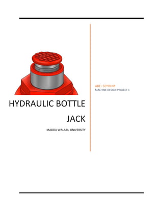
  • 1. HYDRAULIC BOTTLE JACK MADDA WALABU UNIVERSITY ABEL SEYOUM MACHINE DESIGN PROJECT 1
  • 2. Design of hydraulic bottle jack 2 | P a g e ABEL SEYOUM CESR/0038/09 SUBMITTED TO MR ABEBE.M SUBMITION DATE APRIL/18/2019
  • 3. Design of hydraulic bottle jack 3 | P a g e Contents List of figures.................................................................................................................................................5 Abstract.........................................................................................................................................................6 CHAPTER ONE ...............................................................................................................................................8 Introduction...............................................................................................................................................8 1.1 Background...............................................................................................................................8 1.2 introduction.....................................................................................................................................9 1.3 Problem statement...................................................................................................................14 Objectives............................................................................................................................................14 1.4 Significance of the object........................................................................................................15 1.5 Scope and Limitation ..............................................................................................................15 1.6 Methodology...........................................................................................................................15 CHAPTER TWO ........................................................................................................................................18 Literature review.....................................................................................................................................18 2.1 Literature Review..........................................................................................................................18 2.2 Previous works..............................................................................................................................18 2.3 conclusion and recommendation...................................................................................................19 CHAPTER THREE..........................................................................................................................................20 Conceptual Design ..................................................................................................................................20 3.1 Concept Generation......................................................................................................................20 3.2 Material Selection.........................................................................................................................21 2 Material selection for the piston head ............................................................................................26 3.3. Conceptual Design .......................................................................................................................32 CHAPTER FOUR ...........................................................................................................................................33 4 DETAIL DESIGN.....................................................................................................................................33 4.1 Position analysis (Geometry Analysis) ..........................................................................................33 4.2 Force Analysis................................................................................................................................35 4.3Velocity Analysis ............................................................................................................................37 4.4 Component design........................................................................................................................38 CHAPTER FIVE .............................................................................................................................................55
  • 4. Design of hydraulic bottle jack 4 | P a g e 5. CONCLUSION.......................................................................................................................................55 5.1 Result ............................................................................................................................................55 5.2 Recommendation..........................................................................................................................58 References ..................................................................................................................................................59 Appendex A.................................................................................................................................................60
  • 5. Design of hydraulic bottle jack 5 | P a g e List of figures working principle of lever_______________________________________________________________________11 hydraulic bottle jack section view ________________________________________________________________11 Hydraulic bottle jack section view 2 ______________________________________________________________12 Bottle Jack __________________________________________________________________________________13 Geometrical design of bottle jack ________________________________________________________________33 Simple hydraulic jack system ____________________________________________________________________36 (one system with two mechanical advantages), _____________________________________________________37 FBD of piston rod with its cap ___________________________________________________________________38 Piston head__________________________________________________________________________________40 FBD of cap __________________________________________________________________________________40 main cylinder ________________________________________________________________________________42 tangential and radial stress _____________________________________________________________________42 telescopic cylinder ____________________________________________________________________________45 pumping cylinder _____________________________________________________________________________45 reservoir cylinder_____________________________________________________________________________47 cover plate __________________________________________________________________________________47 Handle _____________________________________________________________________________________49 plunger_____________________________________________________________________________________51 link multi view _______________________________________________________________________________52
  • 6. Design of hydraulic bottle jack 6 | P a g e Abstract A Bottle jack is a jack which works on the principle of hydraulics (hence falls under the category of hydraulic jacks) and looks like a bottle in its shape. It can be used for lifting vehicles to undergo repair work or dealing with flat tires. It can also be used in interconnection with more bottle jacks for lifting structures and for some household purposes. With the use of bottle jacks short vertical heights can be achieved. The former model was carefully studied in terms of the design features, specifications, capacity and with the help of new methodology an attempt was made to fabricate a new design that can work horizontally, producing same capacity within the economic range. The work consists of the fabrication of the new model and projects the advantages of the new method over existing methods. The new design was successfully made and was able to fulfill all the required objectives. The following work can be a new eye opener for the design engineers dealing with making the jack work horizontally.
  • 7. Design of hydraulic bottle jack 7 | P a g e ACKNOWLEDGEMENTS It is with a great sense of pleasure that we acknowledge the help and guidance we have received from a numerous people during the course of our stay at Madda Walabu University. My instructor Mr. Abebe M. for providing me with energy, enthusiasm, insight to work on this interesting design project and for all comments given during the design. Moreover, I would like to express my heartfelt and sincere for their priceless guidance and support during my project. Furthermore, I also would like to thank our senior students who give references and motivate us during the project. Not forgetting our fellow friends who gave us a lot of ideas, contributing in our development of the design. Which we also learnt the importance of team working. Abel Seyoum
  • 8. Design of hydraulic bottle jack 8 | P a g e CHAPTER ONE Introduction 1.1Background The personal name Jack, which came into English usage around the thirteenth century as a nickname form of John, came in the sixteenth century to be used as a colloquial word for 'a man (of low status)' (much as in the modern usage 'jack of all trades, master of none'). From here, the word was 'applied to things which in some way take the place of a lad or man, or save human labor'. The first attestation in the Oxford English Dictionary of jack in the sense 'a machine, usually portable, for lifting heavy weights by force acting from below' is from 1679, referring to 'an Engine used for the removing and commodious placing of great Timber. A jack is a mechanical device which uses a screw thread or a hydraulic cylinder to lift heavy loads or apply great linear forces. The most common forms of jacks available in the market are Scissor car jacks, House jacks, Hydraulic jacks, Pneumatic jacks and Strand jacks that are extensively used in Construction, Industrial, Automobile and Engineering segments. In most of the powerful jacks, hydraulic power is14 Used to provide more lift over greater distances. Or, a jack is a device that uses force to lift heavy loads. The primary mechanism with which force is applied varies, depending on the specific type of jack, but is typically a screw thread or a hydraulic cylinder. Jacks can be categorized based on the type of force they employ: mechanical or hydraulic. Mechanical jacks, such as car jacks and house jacks, lift heavy equipmentand are rated based on lifting capacity (for example, the number of tons they can lift). Hydraulic jacktend to be stronger and can lift heavier loads higher, and include bottle jacks and floor jacks. HYDRAULIC JACKS depend on force generated by pressure. Essentially, if two cylinders (a large and a small one) are connected and force is applied to one cylinder, equal pressure is generated in both cylinders. However, because one cylinder has a larger area, the force the larger cylinder produces will be higher, although the pressure in the two cylinders will remain the same. Hydraulic jacks depend on this basic principle to lift heavy loads: they use pump plungers to move oil through two cylinders. The plunger is first drawn back, which opens the suction valve ball within and draws oil into the pump chamber. As the plunger is pushed forward, the oil moves through an external discharge check valve into the cylinder chamber, and the suction valve closes, which results in pressure building within the cylinder.
  • 9. Design of hydraulic bottle jack 9 | P a g e 1.2 introduction 1.2.1 Classification Jacks can be categorized based on the type of force they employ as follows: -  Mechanical Jacks and Hydraulic Jacks  There are also some electrical jacks but the working principle of them is the same as that of either Mechanical or Hydraulic jacks. Mechanical Jacks: - is a devise used to lift a heavy equipment, this type of jack usually rated for a maximum lifting capacity ranging from 1.5 tons to 3 tons. There are some types of Mechanical jacks, some of them are: - Scissor jack Scissor car jacks usually use mechanical advantage to allow a human to lift a vehicle by manual force alone. The jack shown at the right is made for a modern vehicle and the notch fits into a hard point on a unibody. Earlier versions have a platform to lift on a vehicle's frame or axle. Electrically operated car scissor jacks are powered by 12volt electricity supplied directly from the car's cigarette lighter receptacle. The electrical energy is used to power these car jacks to raise and lower automatically. Electric jacks require less effort from the motorist for operation. House jack A house jack, also called a screw jack, is a mechanical device primarily used to lift buildings from their foundations for repairs or relocation. A series of jacks is used and then wood cribbing temporarily supports the structure. This process is repeated until the desired height is reached. The house jack can be used for jacking carrying beams that have settled or for installing new structural beams. On the top of the jack is a cast iron circular pad that the jacking post rests on. This pad moves independently of the house jack so that it does not turn as the acme-threaded rod is turned with a metal rod. This piece tilts very slightly, but not enough to render the post dangerously out of plumb. Advantages of Mechanical Jacks Jack are many advantage rather than disadvantage from its many advantages Jacks same of them are as follows;  The size of the jack is small because it can be shortened and elongated  Its construction is simple  It can be operated and maintained easily.  Easy to carry it moving at where it required  Take a short time to operation  It is small in size and over all weight is so light.
  • 10. Design of hydraulic bottle jack 10 | P a g e  Easy to lift the vehicle and heavy load no need of capital investigation and installation that are relative to cost. Dis advantages of Mechanical Jacks  Jack has disadvantage as it is advantage Cannot be used to lift and supported very heavy equipment  It should always lubricated  It is not used on the even surface  Required more energy for operation.  It is not suitable for women and older due to required more energy. Hydraulic jacks: - before we define hydraulic jacks first let us see, what is hydraulics?  HYDRAULICS: The word hydraulics is based on the Greek word for water, and originally covered the study of the physical behavior of water at rest and in motion. Use has broadened its meaning to include the behavior of all liquids, although it is primarily concerned with the motion of liquids. Hydraulics includes the manner in which liquids act in tanks and pipes, deals with their properties, and explores ways to take advantage of these properties. Although the modern development of hydraulics is comparatively recent, the ancients were familiar with many hydraulic principles and their applications. The Egyptians and the ancient people of Persia, India, and China conveyed water along channels for irrigation and domestic purposes, using dams and sluice gates to control the flow. The ancient Cretans had an elaborate plumbing system. Archimedes studied the laws of floating and submerged bodies. The Romans constructed aqueducts to carry water to their cities. Torricelli, French physicist, Edme Mariotte, and later, Daniel Bernoulli conducted experiments to study the elements of force in the discharge of water through small openings in the sides of tanks and through short pipes. During the same period, Blasé Pascal, a French scientist, discovered the fundamental law for the science of hydraulics. Hydraulic jack is based on the Pascal’s law which states that increase in pressure on the surface of a confined fluid is transmitted undiminished throughout the confined vessel or system. [1]  Hydraulic jacks are mechanical devices used to lift heavy loads, vehicles, weight equipment or apply great forces using hydraulic fluid as the main source of power. These are widely used in automotive, industrial and construction industries. These are sturdy in construction, compact in size, portable and capable of exerting great forces. It consists of two cylinders of different sizes which are connected together by a pipe and a hydraulic fluid or oil. The hydraulic fluid is incompressible and using a pump plunger is forced into the cylinder of the jack. Oil is used because of its stable and self-lubricating nature. When the plunger pulls back, oil is drawn out of the reservoir and it goes inside the pump chamber. When the plunger moves forward, the oil is pushed back into the cylinder. This oil movement builds up pressure in the cylinder. And it is this pressure which leads to the working of the hydraulic jack. It also finds usage in workshops and also lifts elevators in low and medium rise buildings. These can be segmented into two types: Bottle Hydraulic Jack and Floor Hydraulic Jack. Bottles are portable in design; in these the piston is in a vertical position and it supports a bearing pad which touches the object being lifted. Bottle Hydraulic are most appropriate for lifting vehicles (cars, trucks, SUVs, trailers), houses and other heavy objects. In a Floor Jacks, the
  • 11. Design of hydraulic bottle jack 11 | P a g e piston is in a horizontal piston and there is a long arm which provides the vertical motion to a lifting pad. There are wheels and castors in floor jacks. The working principle of all hydraulic jacks is Common but these differ in their shapes and sizes. Hydraulic jacks with varied sizes and specifications are used to lift different types of heavy equipment and vehicles such as bulldozers, forklifts, elevators, trolleys & trailers and excavators. These can also be found in household equipment’s as well like door stoppers, cars, bikes etc. Hydraulic Jacks are high in demand across the globe owing to their sturdy construction, reliable& hassle free operation, unparalleled performance, user-friendly design and less maintenance.  A hydraulic jack is a small device which can lift heavy load with very little effort by the jack operator. It works on the lever principle, if we place a lever under a heavy object we can lift it by rising the free end of the lever. Figure 1 working principle of lever The distance the object is lifted (X) can be a few inches but the free end of the lever has to travel much more distance (Y) than that. And that is the ratio of multiplication of the force. If we move the lever 10 times the distance of the height what we want it may lift the object 1/10th of the distance, we can lift 100 kilos with an effort equivalent with 10 kilos thus we will have to move the lever 10 inches for every inch of lifting. One drawback is that the free end of the lever is limited as to the distance it can travel, so the object can’t be lifted very far from the ground the way to solve that problem is by using a mechanism which allows swinging of the free end of the lever without the object going down again. If we can swing a lever several times we can lift the object for a practical distance “the hydraulic jack allows you to do just that" In this schematic we can see the inside of a hydraulic jack  We see there are two pistons each of them inside their cylinders.  There is also a hydraulic oil reservoir, in fact a liquid would do but b using oil we prevent rust and improve the lubrication of the mechanism. Figure 2 hydraulic bottle jack section view
  • 12. Design of hydraulic bottle jack 12 | P a g e  1st we place the jack in proper place to lift whatever object we want to raise off the ground.  The big piston labeled "A" is in its extreme lower position and its cylinder is almost empty.  We will start by moving upward to small piston labeled "B", which sucks oil in to the small cylinders through automatic valve "C". Fig 2  Once a small cylinder is full we move down the piston "B", we are using a short lever which increases the force several times the liquid in small cylinder is forced out.  closing automatic valve "C" while opening valve "D" forcing the oil in to piston "A" cylinder  The amount of oil pumped in to cylinder "A" is more so piston "A" moves very short distance, thus the lever effect multiplies the force applied to the big piston.  Again we move a small piston "B" upwards in order to recharge its cylinder with another small amount of oil is before automatic valve "C" opens and oil flows from the reservoir in to the small cylinder.  once more we push down the small piston, thus closing valve "C" in inject oil into the big cylinder through valve "D"  then we repeat this action as many times as necessary, until we rise the object we wish to lift which could be a very heavy automobile by repeating a small effort many times, thus gaining a difference in distance between the stroke to the piston in the shore stroke on the big piston.  When we want to want to lower the raised object we simply open the butterfly valve “E” to allow oil to go back to reservoir so the big piston can go down.  This is the way hydraulic jack multiplies human force. Figure 3 Hydraulic bottle jack section view 2 Classification of Hydraulic Jacks According to the source of power  Manually operated jacks (hand or pedal operated)  Power operated jacks (pump is used) According to the lift of ram  High lift  Medium lift  Low lift According to the arrangement of cylinder  Vertical  Horizontal  Inclined According to the number of cylinders  Single cylinder  Multi cylinder According to the construction  Floor mounted jack  Bottle jack  Trolley jack  Two common types of hydraulic jacks include BOTTLE JACKS & FLOOR JACKS
  • 13. Design of hydraulic bottle jack 13 | P a g e Bottle jacks BOTTLE JACKS became popular in the early 1900s when the automobile industry began to take off. Also called hand jacks, bottle jacks provided an easy way for an individual to lift up a vehicle for roadside inspection or service. Their resemblance to milk bottles earned bottle jacks their name—today, they range in size and weight to offer a lifting capability ranging from one hundred to several tons. Bottle jacks feature a vertical shaft, which supports a platform (called a bearing pad) that directly bears the weight of the object as it is lifted. Although they are most commonly used in the automobile industry (1.5 to 5 ton jacks are frequently used to lift cars), bottle jacks have other uses as well. In the medical industry they can be used in hydraulic stretchers and patient lifts. In industrial applications, they can be found as pipe benders used in plumbing, as cable slicers for electrical projects, and as material lifts within warehouses. Their ability to lift heavy loads plays a big role in enabling the repair of large agricultural machinery and in many construction operations. Bottle jacks can be secured within a frame, mounted on a beam, or simply used as they are for easier jack transportation. A bottle jack is a hydraulic jack which resembles a bottle in shape, having a cylindrical body and a neck, from which the hydraulic ram emerges. In a bottle jack the piston is vertical and directly supports a bearing pad that contacts the object being lifted. With a single action piston, the lift is somewhat less than twice the collapsed height of the jack, making it suitable only for vehicles with a relatively high clearance. For lifting structures such as houses the hydraulic interconnection of multiple vertical jacks through valves enables the even distribution of forces while enabling close control of the lift. The bottle hydraulic jack as consists of a cylinder, a piston and lever operated pump and their capacities is to up to 50 tones and lifting height is e. The device pushes against a piston, pressure built in the jack container up to 22in.Large hydraulic jack may be provided with two pumps. In other word is a device used invariably in the in the machinery and equipment. The device itself is light and portable but the device is capable of exerting great force. Floor jacks Unlike bottle jack shafts, the shaft in a floor jacks is horizontal—the shaft pushes on a crank that connects to a lifting pad, which is then lifted horizontally. Floor jacks typically provide a greater range of vertical lift than bottle jacks, and are available in two sizes. The original jack is about four feet long, a foot wide, and weights around 200 pounds—they can lift 4-10 tons. A more compact model was later made, which is about three feet in length, and can lift 11/2 tons. Although mini jacks are also produced, they are not a recognized standard type of floor jack. Typically, one of the first two sizes should be used. Figure 4 Bottle Jack
  • 14. Design of hydraulic bottle jack 14 | P a g e Advantages of Hydraulic Jacks  They are used for heavy equipment’s  Bottle jacks provides an easy for an individual to lift up a vehicle for road side inspection or service  Typically used for shop work  are often used to lift elevators in low and medium rise buildings  Bottle Hydraulic are most appropriate for lifting vehicles (cars, trucks, SUVs, trailers), houses and other heavy objects. 1.3 Problem statement A Car is a motor vehicle with four wheels; usually propelled by an internal combustion engine. In general, it has above 120 parts. Those parts are mostly made by using very heavy materials like steels and the like to create better combustion process and to give long operating life time for the car. But the negative impact of those heavy materials is that the car becomes large and not suitable for maintenance. Predominately, maintenances that has to be performed for lower parts of the car become difficult till the car is lifted some height from the ground and does not create some working space for the mechanic. On the other hand, it is not possible to lift the car by a person so there must be a device that lifts the car a certain height from the ground is called car jack. Basically car jacks now days are provided using either hydraulic system or mechanical system and combination of the two. Under this project I try to design a hydraulic bottle jack that operates under 70KN load and 200mm change in height. Objectives 1.4.1General objectives The main objective of the project is to Design of hydraulic bottle jack. 1.4.2Specific objectives The project also aims at designing of: -  Extension screw  Nut and Cup screw  Solid and Hollow ram  Pump cylinder  Reservoir  Plunger  Stroke calculation  Top cup and base  Handle and stroke(for pump), links & pins(at plunger & links)  Spring at discharge valve  Valves  Ball for relief valve  O-ring seal (for pump piston /cylinder, hollow ram and solid ram plunger)
  • 15. Design of hydraulic bottle jack 15 | P a g e 1.4 Significance of the object This project enables me that  How to design a hydraulic bottle jack  To redesign the bottle jack with good material and cost effectiveness  This project enable us to upgrade our knowledge to design machines in a better way. 1.5 Scope and Limitation 1.5.1 Scope This project is about the designing and fabricating the car jack. The types of car jack that I were used in this project were hydraulic car jack as it is more reliable and easy to operate. The scopes of research were on the designing 7 ton maximum lifting capacity of car jack by using optimization concept. For optimizing the human power, the concepts that will be used in this product was reducing the number of strokes during the lifting operation. By this, the mechanical advantage (the load exerted by the man) while lifting can be reducing. In our design wI were used Technical Drawing (no softwares) of each component of our product. From my analysis, I will propose the best concept of the car jack in terms of easy to operate and lower cost in product development. The scope of this design project is limited to design Hydraulic bottle jack 7ton Maximum lifting capacity  Minimum and maximum lifting height of 150 & 350mm. 1.5.2 Limitations In the process of doing this project I faced out many problems some of them are:  Only for a normal person  There is no proto type for the designed bottle jack  The project can be analyzed based on a material used in the construction  Lack of design experience.  Lack of source of data.  Lack of software knowledge (mostly Microsoft Office) 1.6 Methodology This project has 5 chapters. And we can classify them into two major parts, the first part is an introductory part and the second part is analysis of the project by using the geometric analysis, numerical analysis, Velocity analysis and as well as the detail drawing. The project design is focus on the design Hydraulic bottle jack which is different parameters such as force, stress, strain etc. are calculated by numerical method. Literature Review:
  • 16. Design of hydraulic bottle jack 16 | P a g e In many countries there were developed so many designs regarding to Hydraulic bottle jacks, and they are good and the base for this bottle jack era. But when those designers and scientists developing that thre were some limitations, so from that limitation I’m going to design a new and better Hydraulic bottle jack. Analyze the data: It is the process of evaluating data using analytical and logical reasoning to examine each component of the data provided. This form of analysis is just one of the many steps that must be completed when conducting a research experiment. Material selection: Deals with what type of material is appropriate for the design and project we have. Concept generation: A procedure in which different concepts or ideas are generated to effectively do our project. Component design: Deals with designing each component of the machine or the device. Design analysis: It is a process of evaluating our design in detail, and to examine the drawing parts or components. Conclusion: It is the last procedure in which we summarize or conclude our project by giving different suggestions to update the project we did. To design this project I use the following procedures (block Diagram); - Literature review analysis of the data Material selection Concept generation Concept design
  • 17. Design of hydraulic bottle jack 17 | P a g e Design analysis Conclusion
  • 18. Design of hydraulic bottle jack 18 | P a g e CHAPTER TWO Literature review 2.1 Literature Review In this section, we will review the literatures that are related with Hydraulic Bottle jack and we are going to see the review of the Bottle in the past few Centuries and Decades. 2.2 Previous works Design of mechanical hydraulic jack, India, (July 2014) Have studied that, Hydraulic jack works on the principle of ―Pascal‘s law‖. When the handle is operated, the plunger reciprocates then the oil from the reservoir is sucked into the plunger cylinder during upward stroke of the plunger through the suction valve. The oil in the plunger cylinder is delivered into the ram cylinder during the downward stroke of the plunger through the delivery valve. This pressurized oil lifts the load up, which is placed on top plate of the ram. After the work is completed the pressure in the ram cylinder is released by unscrewing the lowering screw thus the pressure releases and the ram is lowered, then the oil is rushed into the reservoir. It consists of plunger cylinder on one side and ram cylinder on the other side. These two cylinders are mounted on base which is made of mild steel. Plunger cylinder consists of plunger which is used to build up the pressure by operating the handle. Plunger cylinder consists of two non-return valves i.e. one for suction and other for delivery. Ram cylinder consists of ram which lifts the load. The ram cylinder connected to delivery valve of plunger cylinder. It is also consists of lowering screw this is nothing but a hand operated valve used for releasing the pressure in the ram cylinder for get down the load. [1] Design of Hydraulic Bottle Jack, Ethiopia, (June12 2017) …Hydraulic jacks are typically used for shop work, rather than as an emergency jack to be carried with the vehicle. Use of jacks not designed for a specific vehicle requires more than the usual care in selecting ground conditions, the jacking point on the vehicle, and to ensure stability when the jack is extended. Hydraulic jacks are often used to lift elevators in low and medium rise buildings. [2], Steam Power and Mill Work Principles and Modern Practice, us, (1895) "The Bottle-Jack Is Exceedingly Firm and Safe for Short Vertical Lifts, But Is Not Convenient for Pushing in A Horizontal or Oblique Direction." [3] Inbuilt Hydraulic Jack in Automobile Vehicles, India, (April 2013) …Both hydraulic jacks are pivoted on the rectangular struts. The one end of jack is fixed to frame. The rectangular struts are kept hollow for reducing the weight. The rectangular paddles are also pivoted on the other end of struts. Hydraulic jacks are operated by 12 volt DC battery. At a single time, one and two both jacks can work and vehicle can lift from one side and also from two sides as per the requirement. [4] Automatic Hydraulic Jack Inbuilt In A Four Wheeler, India, (August 2016)
  • 19. Design of hydraulic bottle jack 19 | P a g e With some design consideration an inbuilt car lifting mechanism can easily be fitted in all light weight automobiles. The project works on hydraulic power provided by battery. Maintenance and service of the vehicle can be easily done by this project. With this project the usage of automobile can be made easy for women and old people. Some extra automation like solenoid control valve can add great value to the project. The inbuilt jack is operated by battery so it can also be used when the vehicle engine is not started. [5] Modeling of hydraulic systems tailored to diagnostic fault detection systems, USA, (2006) The consistent and reliable operation of hydraulic componentry is paramount for many systems. From spacecraft to the most basic automotive bottle jack an undetected failure can have significant consequences if not noticed in time. Many hydraulic systems have diagnostics capabilities but these are normally very limited in scope. They can detect events only related to specifically monitored components or general system failures. Typically these diagnostic systems are designed after the fact and tuned to meet goals. When hydraulic systems are designed, simulation models are frequently used to gain some idea of the finished systems performance. Rarely is the simulation model designed to accommodate and optimize a diagnostic capability. The number and placement of diagnostic sensors can have a significant effect on the ability of a diagnostic system to resolve faults early in their evolution cycle. This paper describes a technique developed at the Penn State Applied Research Laboratories Systems Operations and Automation Department for the design of hydraulic simulation models that pre-incorporate fault diagnostic advanced design features. This technique is being applied to a US Army M1120 heavy expanded mobility tactical truck (HEMTT) load handling system (LHS) supply vehicle that utilizes a palletized hydraulic loading system. The test vehicle has a hydraulic system that was fully instrumented with sensors for this work. This paper addresses a piece in the diagnostic puzzle that has until now been looked at. Namely what additional features in a simulation model allow for optimal placement and monitoring of the hydraulic system? The researchers have found that this typically leads the readdressing or removing certain engineering assumptions that are typically made when designing simulation models. When this is done the models are more flexible when it comes to diagnostic implementation. [6] 2.3 conclusion and recommendation All those researchers has given contribution for this bottle jack design, and their designs were good. But they didn’t consider cost, availability, maintainability. So for those reasons I am going to design a new and better Hydraulic Bottle Jack by improving those problems as much as possible. As we know in our country materials are not found easily so and they are expensive. My recommendation for those problems is by using better material property, cost and availability we can design a better hydraulic bottle jack.
  • 20. Design of hydraulic bottle jack 20 | P a g e CHAPTER THREE Conceptual Design 3.1 Concept Generation Concept one Driving unit Type Selection Parameter Total (100%) Operating condition (25%) Maintainability (30%) Machinability (15%) Cost (30%) Mechanical 22 28 14 28 92 `Hydraulic 20 24 12 22 78 Electrical 17 15 8 18 58 Concept 2 Handle operating mechanism Mechanism Selection parameter Total (100%) Size (25%) Maintainability (30%) Machinability (15%) Cost (30%) By Hand 23 28 12 26 89 By leg 19 28 10 24 81 Hybrid ( both leg and hand) 15 23 8 19 65 Concept 3 Base shape Shape Selection parameter Total (100%) Machinability (40%) Maintainability (25%) Cost (35%) circular 25 21 24 70
  • 21. Design of hydraulic bottle jack 21 | P a g e Rectangular 35 21 30 86 3.2 Material Selection The following factors should be considered while selecting the material. Availability of the materials Suitability of the materials for the working conditions in service, and abundance on the earth crust. Because it should not be difficult to find it. The cost of the materials. The important properties, which determine the utility of the material, are physical, chemical and important physical properties of some pure metals. Physical Properties of Metals The physical properties of the metals include luster, color, size and shape, density, electric and thermal conductivity, and melting point. The following table shows the important physical properties of some pure metals. Mechanical Properties of Metals The mechanical properties of the metals are those which are associated with the ability of the material to resist mechanical forces and load. These mechanical properties of the metal include strength, stiffness, elasticity, plasticity, ductility, brittleness, malleability, toughness, resilience, creep and hardness. We shall now discuss these properties as follows: Strength. It is the ability of a material to resist the externally applied forces without breaking or yielding. The internal resistance offered by a part to an externally applied force is called stress. Stiffness. It is the ability of a material to resist deformation under stress. The modulus of elasticity is the measure of stiffness. Elasticity It is the property of a material to regain its original shape after deformation when the external forces are removed. This property is desirable for materials used in tools and machines. It may be noted that steel is more elastic than rubber. Plasticity. It is property of a material which retains the deformation produced under load permanently. This property of the material is necessary for forgings, in stamping images on coins and in ornamental work. Ductility. It is the property of a material enabling it to be drawn into wire with the application of a tensile force. A ductile material must be both strong and plastic. The ductility is usually measured by the terms, percentage elongation and percentage reduction in area. The ductile material commonly used in engineering practice (in order of diminishing ductility) are mild steel, copper, aluminum, nickel, zinc, tin and lead.
  • 22. Design of hydraulic bottle jack 22 | P a g e Note:-The ductility of a material is commonly measured by means of percentage elongation and percentage reduction in area in a tensile test. Ferrous Metals The ferrous metals are those which have iron as their main constituent. The ferrous metals commonly used in engineering practice are cast iron, wrought iron, steels and alloy steels. The principal raw material for all ferrous metals is pig iron which is obtained by smelting iron ore with coke and limestone, in the blast furnace. Cast Iron The cast iron is obtained by re-melting pig iron with coke and limestone in a furnace known as cupola. It is primarily an alloy of iron and carbon. The carbon content in cast iron varies from 1.7percent to 4.5 percent. It also contains small amounts of silicon, manganese, phosphorous and sculpture. The carbon in a cast iron is present in either of the following two forms:- 1. Free carbon or graphite, and 2. Combined carbon or cementite. Since the cast iron is a brittle material, therefore, it cannot be used in those parts of machines which are subjected to shocks. The properties of cast iron which make it a valuable material for engineering purposes are its low cost, good casting characteristics, high compressive strength, wear resistance and excellent machinability. The compressive strength of cast iron is much greater than the tensile strength. Following are the values of ultimate strength of cast iron: Tensile strength = 100 to 200MPa Compressive strength = 400 to 1000MPa Shear strength = 120 M Pa * 1MPa = 1MN/m2 = 1 × 10⁶ N/m2 = 1 N/mm2 Alloy Cast Iron The cast irons contain small percentages of other constituents like silicon, manganese, sulphur and phosphorus. These cast irons may be called as plain cast irons. The alloy cast iron is produced by adding alloying elements like nickel, chromium, molybdenum, copper and manganese in sufficient quantities. These alloying elements give more strength and result in improvement of properties. The alloy cast iron has special properties like increased strength, high wear resistance, corrosion resistance or heat resistance. gears, automobile parts like cylinders, pistons, piston rings, crank cases, crankshafts, camshafts, sprockets, wheels, pulleys, brake drums and shoes, parts of crushing and grinding machinery etc. Steel it is an alloy of iron and carbon, with carbon content up to a maximum of 1.5%. The carbon occurs in the form of iron carbide, because of its ability to increase the hardness and strength of the steel. Other elements e.g. silicon, sulphur, phosphorus and manganese are also present to greater or lesser amount to impart certain desired properties to it. Most of the steel produced now-a-days is plain carbon steel or simply carbon steel. Carbon steel is defined as steel which has its properties mainly due to its carbon content and does not contain more than 0.5% of silicon and 1.5% of manganese. The plain carbon steels varying from 0.06% carbon to 1.5% carbon are divided into the following types depending upon the carbon content. 1. Dead mild steel — up to 0.15% carbon 2. Low carbon or mild steel — 0.15% to 0.45% carbons 3. Medium carbon steel — 0.45% to 0.8% carbon
  • 23. Design of hydraulic bottle jack 23 | P a g e 4. High carbon steel — 0.8% to 1.5% carbon Alloy Steel Alloy steel may be defined as steel to which elements other than carbon are added in Sufficient amount to produce an improvement in properties. The alloying is done for specific purposes to increase wearing resistance, corrosion resistance and to improve electrical and magnetic properties, which cannot be obtained in plain carbon steels. The chief alloying elements used in steel are nickel, chromium, molybdenum, cobalt, vanadium, manganese, silicon and tungsten Factor of safety Many times workers have to work below heavy load such a high risk of work leads to select higher factor of safety values. The dropping or slipping of weight is life hazards. So it has to be foolproof. Select factor of safety as ‘4’. Since the shear stress at the yield point in a simple tension test is equal to one-half the yield stress. Physical and Mechanical properties of Materials Density, ρ Ρ (Mg/m2 ) Ferrous Non-ferrous Cast Irons High Carbon Steels Medium Carbon Steels Low Carbon Steels Low Alloy Steels Stainless Steels Aluminium Alloys Copper Alloys Lead Alloys Magnesium Alloys Nickel Alloys Titanium Alloys Zinc Alloys 7.05 - 7.25 7.8 - 7.9 7.8 - 7.9 7.8 - 7.9 7.8 - 7.9 7.6 - 8.1 2.5 - 2.9 8.93 - 8.94 10 - 11.4 1.74 - 1.95 8.83 - 8.95 4.4 - 4.8 4.95 - 7
  • 24. Design of hydraulic bottle jack 24 | P a g e Young’s Modulus, Е Е(GPA) Ferrous Non-ferrous Cast Irons High Carbon Steels Medium Carbon Steels Low Carbon Steels Low Alloy Steels Stainless Steels Aluminum Alloys Copper Alloys Lead Alloys Magnesium Alloys Nickel Alloys Titanium Alloys Zinc Alloys 165 - 180 200 - 215 200 - 216 200 - 215 201 - 217 189 - 210 68 - 82 112 - 148 12.5 - 15 42 - 47 190 - 220 90 - 120 68 - 95 Yield stress, σy and Tensile strength, σts σy (MPa) σts (MPa) Ferrous Non-ferrous Cast Irons High Carbon Steels Medium Carbon Steels Low Carbon Steels Low Alloy Steels Stainless Steels Aluminum Alloys Copper Alloys Lead Alloys Magnesium Alloys 215 - 790 400 - 1155 305 - 900 250 - 395 400 - 1100 170 - 1000 30 - 500 30 - 500 8 - 14 70 - 400 350 - 1000 550 - 1640 410 - 1200 345 - 580 460 - 1200 480 - 2240 58 - 550 100 - 550 12 - 20 185 - 475
  • 25. Design of hydraulic bottle jack 25 | P a g e Nickel Alloys Titanium Alloys Zinc Alloys 70 - 1100 250 - 1245 80 - 450 345 - 1200 300 - 1625 135 - 520 Fracture Toughness (Plane Strain), KIC KIC (MPa√m) Ferrous Non-ferrous Cast Irons High Carbon Steels Medium Carbon Steels Low Carbon Steels Low Alloy Steels Stainless Steels Aluminum Alloys Copper Alloys Lead Alloys Magnesium Alloys Nickel Alloys Titanium Alloys Zinc Alloys 22 – 54 27 - 92 12 - 92 41 - 82 14 - 200 62 - 280 22 - 35 30 - 90 5 - 15 12 - 18 80 - 110 14 – 120 10 - 100 Material selection for the Components 1 Material selection for the piston rod A material to be selected for this piston rod must have the following properties  High strength, harden ability and resistance.  High compressive strength to support the load.  High creep and wear resistance with good surface finish.  Relatively low cost to the other grades of steel
  • 26. Design of hydraulic bottle jack 26 | P a g e Materials Selection factor Material property (30%) Availability (30%) Cost (40%) Total (100%) Cast iron 23 27 36 86 Low alloy steel 28 26 32 86 High carbon steel 25 28 34 87 The material I selected for solid piston rod is stainless still b/se it has best cost and availability advantages than low alloy steel and have a property for all of those criteria’s written above. This stainless steel have the following Mechanical and Physical properties: - Yield strength = 1155Mpa Ultimate strength = 860Mpa Shear strength = 150Mpa Modulus of elasticity = 190GPa Modulus of rigidity = 75GPa 2 Material selection for the piston head Piston head and Piston rod have the same materials, thus we can use the same material for the piston rod too. i.e. Stainless steel. 3 Material selection for the cap Since the cap is in directing contact the load it has to be hard enough to contain it and should not be easily failing due to the direct high compressive stress and it must have high Fracture toughness(Plane strain) this depends on the correct selection of the material for the cap. Also local availability and cost are also determinant factor for selection. Materials Selection factor Total (100%) Material property (30%) Availability (30%) Cost (40) Low carbon steel 26 24 36 86 Stainless steel 29 23 32 84 High carbon steels 22 26 37 85 The material that I selected for the cap is Low carbon steel, b/se from the table low carbon steel gets high selection factor than the others in total. Low carbon steel have the following material and physical properties:- Density, ρ = 7.8Mg/m3
  • 27. Design of hydraulic bottle jack 27 | P a g e Young’s Modulus, Е = 210GPa Yield stress, σy = 300MPa Tensile strength, σts = 400MPa Fracture Toughness (Plane Strain), KIC= 60MPa√m 4 Material selection for main cylinder A material for main cylinder must have high stress value b/se of high internal pressure. Material Selection factor Total (100%) Manufacturing feasibility (35%) Availability (35%) Material property (30%) Low carbon steel 27 27 29 83 Stainless steel 32 30 26 88 Cast iron 28 31 26 85 A material that I choose for the main cylinder is stainless steel, low carbon steel have good material property but its manufacturing feasibility and local availability it is difficult to find it. This stainless steel have the following Mechanical and Physical properties: - Yield strength = 520Mpa Ultimate strength = 860Mpa Shear strength = 150Mpa Modulus of elasticity = 190GPa Modulus of rigidity = 75GPa 5 Material selection for pumping cylinder The material that I choose must have the following criteria’s  It must have to be available in local area.  Corrosion resistant and chemical stability  Easy to manufacture
  • 28. Design of hydraulic bottle jack 28 | P a g e Martial Selection factor Total (100%) Material property (35%) Availability (30%) Cost (35%) High carbon steel 33 28 32 93 Low alloy steel 32 27 29 88 stainless steel 30 27 30 87 The material that I choose for the pumping cylinder is high carbon steel, This high carbon steel have the following Mechanical and Physical properties: - Density, ρ = 7.15Mg/m3 Young’s Modulus, Е = 210GPa Yield stress, σy = 600MPa Tensile strength, σts = 700MPa Fracture Toughness (Plane Strain), KIC= 50MPa√m 6 Material selection for pump handle The handle should have to fulfill the following criteria’s  It should be hard  It should be not brittle  Good resistance to corrosion and rust  Cost effective  Easy to maintain  Ease of manufacturability ` Materials Selection factor ` Total (100%) Cost (35%) Material property (35%) Availability (30%) Red brass 26 31 26 83 SAE1020 annealed 28 26 28 82 Ductile cast iron 32 30 28 90 The material that I choose for handle is ductile cast iron, Ductile cast iron have the following energy properties of material: -
  • 29. Design of hydraulic bottle jack 29 | P a g e Yield Strength (MPa) = 276 Ultimate Strength (MPa) = 414 Modulus of Resilience, (kJ/m3) = 186 Modulus of Toughness, (kJ/m3) = 128755 7 Material selection for plunger Since the plunger have high tensile stress, the material should fulfill the following criteria’s: -  High compressive strength to support the load  Give good surface finish  Relatively low cost, Materials Selection parameters Total (100%) Availability (30%) Material property (30%) Cost (40%) Alcoa 2017 27 26 30 83 `type 304 stainless 28 28 33 89 Ductile cast iron 27 28 33 88 As we see from the tabele the material that I choose for plunger is type 304 stainless steel, Type 304 stainless have the following energy properties of material: - Yield Strength (MPa) = 207 Ultimate Strength (MPa) = 586 Modulus of Resilience, (kJ/m3) = 103 Modulus of Toughness, (kJ/m3) = 195199 8 Material selection for basement The material for the basement should have corrosion resistance and high strength, ` materials Selection factor Total (100%) Material property (35%) Cost (35%) Availability (30%) Steel (annealed) 33 32 28 93 Alcoa 2017 32 30 27 89 Cast iron 32 30 26 88 From the table the material that I choose for the basement is steel (annealed),
  • 30. Design of hydraulic bottle jack 30 | P a g e Steel (annealed) have the following material properties: - Yield strength = 294.8Mpa Tensile strength = 394.0Mpa Modulus of elasticity = 207GPa Telescope cylinder 9 Material selection for the Telescope cylinder The selection criteria’s are: -  Good mechanical property  It is strong and ductile  Good in machinability  Good surface finish  High corrosion resistant  Is light in weight, these minimize the weight of the jack Materials Selection factor Total (100%) Material property (35%) Availability (30%) Cost (35%) Steel 0.6% carbon 33 28 32 93 Cast iron 31 27 33 91 Stainless steel 32 28 32 92 Steel 0.6% carbon is selected because it fulfills the above criteria’s. It have the following material properties: - Yield strength = 515MPa Shear strength = 310MPa Modulus of elasticity = 207GPa 10 material selection for cover plate Since the cover plate is not directly subjected to the pressure of the oil, then the material that select for this doesn’t have problem if it have low tensile strength. Criteria’s for cover plate is good surface finish, high corrosion resistance … Material Selection factror Total (100%) Cost (40%) Availability (35%) Manufacturability (25%) Stainless steel 38 32 22 92 Cast iron 35 30 21 86
  • 31. Design of hydraulic bottle jack 31 | P a g e Mild steel 33 30 22 85 The material that I selected for cover plate is stainless steel, Stainless steel have the following material properties: - Yield strength = 520Mpa Ultimate strength = 860Mpa Shear strength = 150Mpa Modulus of elasticity = 190GPa Modulus of rigidity = 75GPa 11 material selection for Link Its function is to connect the socket and the base, thus the material should have to have good tensile strength and relatively low cost. Materials Selection factor Total (100%) Cost (35%) Availability (30%) Material property (35%) 0.6% carbon steel 34 28 33 95 Alcoa 2017 31 25 31 87 Mild steel 32 27 30 89 Te material that I selected for the link is 0.6% carbon steel. 0.6% carbon steel have the following properties: - Yield strength = 515Mpa Shear strength = 320Mpa Modulus of elasticity = 207GPa 12 material selection for pump handle socket As we know pump handle socket transmits force from handle to pump, so the socket handle must have high strength The material that I selected for the pump handle socket is 0.6% carbon steel. The material property of 0.6% carbon steel is: - material Selection parameter Total (100%) Cost (35%) Availability (30%) Material property (35%) 0.6% carbon steel 33 28 34 95 Stainless steel 32 29 32 93 Cast iron 31 28 32 91
  • 32. Design of hydraulic bottle jack 32 | P a g e Yield strength = 515Mpa Shear strength = 320Mpa Modulus of elasticity = 207GPa 13 Material selection for reservoir cylinder The reservoir only stores the oil and is not subjected to any severe stress. Thus any type of iron used in pipe manufacture can be selected as reservoirs cylinder material but its inner walls must have to prevent any chemical attached and rust. material Selection factor Total (100%) Material property (35%) Cost (35%) Availability (30%) Stainless 33 32 28 93 Ductile cast iron 31 30 28 89 Mild steel 32 28 28 88 The material that I selected for the reservoir is stainless Stainless steel have the following material properties: - Yield strength = 520Mpa Ultimate strength = 860Mpa Shear strength = 150Mpa Modulus of elasticity = 190GPa Modulus of rigidity = 75GPa 3.3. Conceptual Design Design considerations Load (W) = 07ton (7KN) Lift range (L) = 20cm (350mm – 150mm) Operating Pressure (p) = 25 M Pa Man effort put on the handle (e) = 20 Kg No. of strokes for lifting load (n) = 150
  • 33. Design of hydraulic bottle jack 33 | P a g e CHAPTER FOUR 4 DETAIL DESIGN 4.1 Position analysis (Geometry Analysis) Position refers to the location of an object. The following sections will address the position of points and links. Figure 5 Geometrical design of bottle jack Geometric Analysis deals with the; determination of the lifting height, overall dimensions of the part of the maximum and minimum lifting height Considering that the above sketch can be taken as a model to a particular hydraulic bottle jack with the given parameters the dimensions analysis of the given drawing (sketch) can be computes and interpreted as follows. Given values: - . The maximum lifting height, H max = 350mm
  • 34. Design of hydraulic bottle jack 34 | P a g e The minimum lifting height, H min =150mm Then find the lifting height of hydraulic bottle jack is given by:- ΔH = H max - H min ΔH = 350mm – 150mm ΔH = 200mm Assumptions Once again consider the above sketch of the given jack. The head thickness of the piston rod actually these parameters should have to be determined after design analysis of the piston cap but we can assume some standard value to the thickness since it may help to find the other parameters. Assumed dimensions Magnitudes (mm) Thickness of piston head tp 16 Diameter of piston dp 15 The unthreaded portion height of the cover plate, b 19 The thickness of the base 25 Diameter of cup, dc 15 And assume q is equal to 2.3 of h2 35.21 Now h1, h2 and h3 (at labeled in the sketch) can be found as follows: From the given the minimum left height of the jack is; Hmin=150mm. H min = h1 + 2.3q + tb + tp 150 = h1 +81+25+16 h1 = 53mm. ℎ2=2q = 2.3(35.21)= 81mm Then we can find h3 in terms of h1, h2 and tb as follows 𝐻𝑚𝑎𝑥=ℎ1+ℎ2+ℎ3+𝑡𝑏 ℎ3=350−53−81−25=191𝑚𝑚 As it can be seen from the sketch h3 is not the height of the piston (instead) it is portion of the height at the piston ℎ𝑝(ℎ𝑒𝑖𝑔ℎ𝑡 𝑜𝑓 𝑝𝑖𝑠𝑡𝑜𝑛)=ℎ3+𝑞 hp =191+ 35.21 = 226.21mm
  • 35. Design of hydraulic bottle jack 35 | P a g e 4.2 Force Analysis This work describes a procedure for determining the mechanical advantage and efficiency of a small hydraulic jack. The testing procedure and required calculations demonstrate how the efficiency of a simple machine can be determined, and how multiple mechanical advantages in a simple machine have a multiplying effect, rather than an adding effect. The cost to set up the experiment is relatively low, yet very informative for the students. Hydraulic jacks provide a means of lifting loads that otherwise could not be lifted by conventional mechanical (screw and scissors) jacks. A common hydraulic jack with a lever arm and pump has two Mechanical Advantages (MA) built into it. One MA is due to the lever arm and the other is due to the ratio of the ram piston diameter squared (D2 ) to the pump piston diameter squared (d2 ), D2 / d2 . The two MA’s combine in a manner that results in a multiplying effect rather than an adding effect, which yields a much larger overall MA. The efficiency of a jack can be determined from the basic definition of efficiency, which is output / input. A hydraulic jack has a relatively large overall MA due to the lever arm and the ratio of the ram piston diameter squared to the pump piston diameter squared. The MA due to the lever arm can be demonstrated and determined by analyzing the simple lever arm shown in Figure Point A is the lever arm pivot point, Point B is where the lever arm applies an output force (FOLA = force out, lever arm) to the jack’s pump and Point C is where the input force (FILA = force in, lever arm) to the system is applied, usually by hand. Summing moments about Point A yields; ∑MA = 0 = (FOLA * l1) – (FILA * l2) Or (FOLA * l1) = (FILA * l2) Or FOLA / FILA = l2 / l1 The mechanical advantage due to the lever arm is either of the above ratios, or MA lever arm = FOLA / FILA = l2 / l1. Eqn. (1) It is usually difficult to determine FOLA, but easy to measure l1 and l2, and therefore possible to calculate MA lever arm. The mechanical advantage due to the ratio of the ram diameter squared to the pump diameter squared can be developed by analyzing the basic fluid principles of the jack. A simplified hydraulic jack is shown in Figure. Point A is where the force into the system is applied (FILA) and Point B is where the force out of
  • 36. Design of hydraulic bottle jack 36 | P a g e the system (FOHS = force out, hydraulic system) is used to lift a load. In the case of a jack the force out of the lever arm (FOLA) is equal to the force into the hydraulic system (FIHS) at the pump. The definition of fluid pressure is a force per unit area, or in equation form, P = F /A EQN. (2) Where P = pressure (N/m2 ), F = force (N), and A = area (m2 ) Figure 6 Simple hydraulic jack system The pressure throughout the hydraulic fluid is assumed to be constant, and for Figure 2 the following applies, P = FOHS / AD = FIHS / Ad Where P = the pressure of the hydraulic fluid in the jack (N/m2 ) AD = the area of the ram piston (m2 ) and Ad = the area of the pump piston (m2 ) Rearranging the above yields FOHS / FIHS = AD / Ad = (p D2 /4) / (p d2 /4) = D2 / d2 The mechanical advantage of the hydraulic system is any of the above ratios, or MA hydraulic system = FOHS / FIHS = AD / Ad = D2 / d2 Eqn (3) Measuring the piston diameters is usually easier than measuring the forces into and out of the hydraulic system. Total mechanical advantage Figure, demonstrates how two MAs, MA1 and MA2, can be manipulated to determine the overall MA total.
  • 37. Design of hydraulic bottle jack 37 | P a g e Figure 7 (one system with two mechanical advantages), MAtotal = Out / In = 30 / 5 = 2 * 3 = 6 Figure shows that the total system MA is determined by taking the ratio of the output to the input, or by multiplying the individual MAs. For the topic at hand, the total mechanical advantage of the hydraulic jack would be determined by multiplying the MA of the lever arm by the MA of the hydraulic system, Or MAtotal = MAlever arm * MAhydraulic system The efficiency of the hydraulic jack can now be determined from the following µ = (Output / Input) * 100 = (Output Force / (Input Force * MAtotal)) * 100 = (FOHS / (FILA * MAtotal)) * 100 Eqn. (4) Where µ= the jack efficiency (%) 4.3Velocity Analysis Velocity analysis involves determining “how fast” certain points on the links of a mechanism are traveling. Velocity is important because it associates the movement of a point on a mechanism with time. Often the timing in a machine is critical. As we know the velocity of hydraulic bottle jack is Linear Velocity (Rectilinear) And the equation is: - V = lim 𝛥𝑡−0 𝑑𝑅 𝑑𝑡 Eqn. 1 And for short time period as V ≈ 𝛥𝑅 𝛥𝑡 Eqn. 2 A point can move along either a straight or curved path. As seen in the earlier chapters, many links are constrained to straight-line, or rectilinear, motion. For points that are attached to a link that is restricted to rectilinear motion, equations (1) and (2) can be used to calculate the magnitude of the velocity. The orientation of the linear velocity vector is simply in the direction of motion, which is usually obvious. Now let’s do the velocity analysis for the piston. We have the height of piston = 226.21mm = 0.22621m Assumption  ΔTime (Δt) = 15sec  The piston moves at constant rate W.K.T the equation for linear velocity 𝛥𝑅 𝛥𝑡 = 0.22621 15 = V
  • 38. Design of hydraulic bottle jack 38 | P a g e 𝑽 = 𝟏𝟓 ∗ 𝟏𝟎 − 𝟑 𝒎/𝒔𝒆𝒄 = 𝟏𝟓𝒎𝒎/𝒔𝒆𝒄 4.4 Component design 4.4.1 Design of Piston rod Free body diagram The piston rod design of a hydraulic cylinder is highly stressed and therefore it should be able to resist the bending and the compressive force that it may encounter during it operation without buckling. The piston should design in such a way that it is able to support a given load without experiencing a sudden change in its configuration.  Configuration of the piston rod (ram) The piston rod selected for this jack is solid rod since screw extension is needed.  Head of the piston inside the cylinder The head should be designed in such a way that:  The seal should be well mounted to it and completely prevented leakage of the oil.  The head of the piston should be slightly extended radially (wide) so that the seal will not be squeezed and bind when the load is lowered.  There should be small clearance (usually 2mm) between the head and the walls of the cylinder to minimize wear due to friction. The height of the piston rod including its head and cup is Hp = h3 + q = 191 + 35.21 = 226.21mm But when the jack is at the minimum lift of height, the total height of the jack assembly above the base of the main (isolating) cylinders is: ℎ𝑝 = ℎ1 + 0.05 ∗ ℎ1 + 𝑏 + 𝑡𝑝 = 53 + 53 ∗ 0.05 + 19 + 16 ℎ𝑝 = 90.65 ≈ 91𝑚𝑚. This total height have to be completely occupied by the piston so that all the oil in the main cylinder will return back to the reservoir when the load is lowered thus to satisfy this total height of the piston should be adjusted, that hp=95mm. Design analysis The piston rod may fail in two ways:  Failure due to compressive stress (crushing)  Failure due to instability (buckling) Figure 8 FBD of piston rod with its cap
  • 39. Design of hydraulic bottle jack 39 | P a g e The cross section of the rod or critical loading should be calculated after considering whether it is stressed rod or column. This consideration could be checked by the following approach. If the length of the rod to least cross actuation dimension ratio is less than or equals to 11. Then the piston rod is considered as stressed otherwise considered as a column. Mathematically, 𝐿 𝐷 ≤ 11, 𝑓𝑜𝑟 𝑠ℎ𝑜𝑟𝑡 𝑐𝑜𝑙𝑢𝑚𝑛 𝐿 𝐷 ≥, 𝑓𝑜𝑟 𝑙𝑜𝑛𝑔 𝑐𝑜𝑙𝑢𝑚𝑛 Also since the piston is round shaped,‘d’ can be substituted by 𝐾∗√12, 𝐾 = √(𝐼/𝐴) Where, K is the slenderness ratio, 𝐼(𝑀𝑜𝑚𝑒𝑛𝑡 𝑜𝑓 𝑖𝑛𝑒𝑟𝑡𝑖𝑎) = 𝜋∗𝑑4 64 A (Area of the piston) = 𝜋∗𝑑4 4 Substitute values 𝐿 𝐾 ∗ √12 ≤ 11, → 𝐿 𝐾 ≤ 11(√12), → 𝐿 𝐾 ≤ 40 Thus √(((𝜋 ∗ 𝑑4 )/64)/((𝜋 ∗ 𝑑4 )/4)) = 𝑑/4 𝐾 = 𝑑 4 Therefore, take 𝑑𝑝=15mm (from geometry analysis) and L= ℎ𝑝 = 226.21mm. 226.21 15/4 ≤ 40 → 60.32, 𝑙𝑜𝑛𝑔 𝑐𝑜𝑙𝑢𝑚𝑛 𝑡𝑦𝑝𝑒 Thus, the piston is long and will not fail due to compressive stress crushing and buckling Design for crushing 𝑑𝑖𝑎𝑚𝑒𝑡𝑒𝑟 𝑑𝑝 = 15𝑚𝑚 𝑚𝑎𝑥𝑖𝑚𝑢𝑚 𝑙𝑜𝑎𝑑 𝑊 = 70𝐾𝑁 𝑇𝑎𝑘𝑒 𝑓𝑎𝑐𝑡𝑜𝑟 𝑜𝑓 𝑠𝑎𝑓𝑒𝑡𝑦 𝑁 = 2 Next find the allowable stress, 𝜎𝑎𝑙𝑙 = 𝜎𝑦 𝑁 = 1155 2 = 577.5𝑀𝑝𝑎 On the other hand, 𝜎𝑎𝑙𝑙 = 𝑤𝑐𝑟 𝜋 ∗ 𝑑𝑝2 4 ⁄ → 577.5 = 𝑤𝑐𝑟 𝜋 ∗ 152 4 𝑤𝑐𝑟 = 102.052𝐾𝑁 This is greater than of working load, 𝑤𝑐𝑟 > 𝑊 → 102.05𝐾𝑁 > 70 𝐾𝑁, 𝑡ℎ𝑒𝑛 𝑡ℎ𝑒 𝑑𝑒𝑠𝑖𝑔𝑛 𝑖𝑠 𝑠𝑎𝑓𝑒. 4.4.2 Design of piston head The head of the piston is taken as a uniform circular flat plate. The pressure of the oil acts upon the plate uniformly.
  • 40. Design of hydraulic bottle jack 40 | P a g e The mechanical properti4es for piston rod and piston head are the same, Design analysis 𝜎𝑎𝑙𝑙 = 𝜎𝑦 𝑁 = 1155 2 = 577.5𝑀𝑝𝑎 𝑝 = 𝑊 𝐴 = 𝑊 𝜋 ∗ 𝑑22 4 ⁄ = 70000 𝜋 ∗ 252 4 ⁄ = 142.6𝑀𝑃𝑎 𝑡ℎ𝑒𝑎𝑑 = 0.433 ∗ 𝑑𝑝√ 𝑝 𝜎𝑎𝑙𝑙 = 0.433 ∗ 15√ 142.6 577.5 = 3.22𝑚𝑚 ≈ 3𝑚𝑚 4.4.3 Design of cap The cap is upper part of the piston rod on which the load is placed. It is the only part of the whole jack which is physical contact with the profile of the load. The upper profile of the cap should be designed in such a way that the load will not translate (slide) horizontally during operation, thus the geometrical shape of the upper plate of the cap should be carefully selected and it must be able to grip the load in a fixed horizontal position. Design Analysis The cap of the piston is subjected to high compressive stress of the load. Now considering shearing of the cap at the joint with the piston rod I have. 𝜏𝑎𝑙𝑙 = 𝑊 𝐴𝑡 = 𝑊 𝜋 ∗ 𝑡𝑝 ∗ 𝑑𝑝 = 70000 𝜋 ∗ 16 ∗ 15 = 92.84𝑀𝑃𝑎 Where 𝜏𝑎𝑙𝑙 − 𝑎𝑙𝑙𝑜𝑤𝑎𝑏𝑙𝑒 𝑠ℎ𝑒𝑎𝑟 𝑠𝑡𝑟𝑒𝑒 𝑊 − 𝑔𝑖𝑣𝑒𝑛 𝑙𝑜𝑎𝑑 𝐴𝑠 = 𝑠ℎ𝑒𝑎𝑖𝑛𝑔 𝑎𝑟𝑒𝑎 𝑒𝑞𝑢𝑎𝑙 𝑤𝑖𝑡ℎ 𝑑𝑖𝑎𝑚𝑒𝑡𝑒𝑟 𝑜𝑓 𝑡ℎ𝑒 𝑝𝑖𝑠𝑡𝑜𝑛 𝑎𝑛𝑑 ℎ𝑒𝑖𝑔ℎ𝑡 𝑜𝑓 𝑡ℎ𝑒 𝑐𝑎𝑝 And find the factor of safety: 𝜏𝑎𝑙𝑙 = 𝜏𝑦 𝑁 → 92.84𝑀𝑃𝑎 = 620 𝑁 → 𝑁 = 6.67 This indicates that the thickness assumed (tp) is safe. Also consider crushing stress of each extended rectangular shapes on the upper surface of the cap we have the following analysis: Figure 9 Piston head Figure 10 FBD of cap
  • 41. Design of hydraulic bottle jack 41 | P a g e Thus the compression stress is: 𝜎𝑐 = 𝑊 𝐴𝑐 Where; σc – compressive stress W – Given load Ac – critical Area Let we need n such structure on the upper surface of the cap to minimize sliding of the loading. Figure A- square end geometrical shape at the middle of the Surface let these are 4 in number. Figure B- rectangular geometry shapes (half of the above shapes) at the profile of the cap. Let these are 8 in number. Assume there will be 8 square shaped extended surfaces 𝜎𝑐 = 𝑊 𝑛 ∗ 𝐴𝑐 = 𝜎𝑦 𝑁 𝜎𝑐 = 70000𝑁 8 ∗ 𝑤2 = 1155𝑀𝑃𝑎 6.67 → 𝑤 = 50.53𝑚𝑚 ≅ 51𝑚𝑚 The next task is determining the diameter of the cap; FBD Then find the total tearing area of the cap: 𝐴𝑡𝑒𝑎𝑟 = 4 ∗ 𝑡𝑝 ∗ (2 ∗ √( 𝑑𝑐 2 4 − 𝑑𝑝 2 4 )) = 8 ∗ 16𝑚𝑚 ∗ √ 𝑑𝑐 2 4 − 152 4 = 128 ∗ √𝑑𝑐 2 − 152 𝑛𝑒𝑥𝑡 𝑏𝑦 𝑢𝑠𝑖𝑛𝑔 𝑎𝑙𝑙𝑜𝑤𝑎𝑏𝑙𝑒 𝑠ℎ𝑒𝑎𝑟 𝑓𝑖𝑛𝑑 𝑑𝑐 𝜏𝑎𝑙𝑙 = 𝑊 128𝑚𝑚 ∗ √𝑑𝑐 2 − 152 92.84 = 70000 128𝑚𝑚 ∗ √𝑑𝑐 2 − 152 → 𝑑𝑐 = 15.08𝑚𝑚
  • 42. Design of hydraulic bottle jack 42 | P a g e 4.4.4 Design of main cylinder The basic function of the hydraulic cylinder is to convert fluid power in to linear mechanical lift force. In doing so, the cylinder is subjected to internal pressure of the fluid (oil) thus it is critical part of the jack and needs through the design. Since the internal pressure should be high enough to sustain the load, then the cylinder must be heavy cylinder which is expected to be thick to sustain the pressure. Figure 11 main cylinder Design analysis In hydraulic cylinder design the wall thickness it is closed so that the stress at the working pressure (P) is less than the yield strength of the wall. Stress over the selection of the walls cannot be assumed to be uniformly distributed. The walls develop both tangential and radial stresses with values which depend up on the radius. First find the thickness and pressure of the walls by using lame’s equation as follows. The cylinder is subjected to for radial and tangential stress (𝜎𝑟 & 𝜎𝑡) respectively. In the next we present the effects of radial and tangential stresses diagrammatically. A) B) Figure 12 tangential and radial stress
  • 43. Design of hydraulic bottle jack 43 | P a g e We know the equations 𝜎𝑟 = 𝑝𝑟𝑖 2 𝑟0 2 − 𝑟1 2 ∗ (1 − 𝑟0 2 𝑟2 ) 𝑎𝑛𝑑 𝜎𝑡 = 𝑝𝑟𝑖 2 𝑟0 2 − 𝑟1 2 ∗ (1 + 𝑟0 2 𝑟2 ) Known boundary conditions For Radial stress 𝜎𝑟𝑚𝑎𝑥 = 𝑟 = 𝑟𝑖 𝜎𝑟𝑚𝑖𝑛 = 𝑟 = 𝑟0 For tangential stress 𝜎𝑡𝑚𝑎𝑥 = 𝑟 = 𝑟𝑖 𝜎𝑡𝑚𝑖𝑛 = 𝑟 = 𝑟0 By substituting the values and I get the following: F or radial stress: 𝜎𝑟𝑚𝑎𝑥 = −𝑃 𝜎𝑟𝑚𝑖𝑛 = 0 F or tangential stress: 𝜎𝑡𝑚𝑎𝑥 = 𝑝𝑟𝑖 2 𝑟0 2− 𝑟1 2 ∗ (1 + 𝑟0 2 𝑟2 ) 𝜎𝑡𝑚𝑖𝑛 = 𝑝𝑟𝑖 2 𝑟0 2− 𝑟1 2 ∗ (1 + 𝑟0 2 𝑟2 ) Now we can select different approaches (maximum normal stress theory, maximum shear stress theory or maximum strain theory) to evaluate the failure of the cylinder. Considering the maximum tangential stress and follow the maximum strain theory we get the following equation called Bernie’s equation. 𝑡 = 𝑑1 2 ∗ (√ 𝜎𝑡 + (1 − 𝜇) ∗ 𝑝𝑖 𝜎𝑡 − (1 + 𝜇) ∗ 𝑝𝑖 − 1 ) Find the known values: 𝜎𝑡 = 𝜎𝑦 𝑁 = 520 2.5 = 208𝑀𝑃𝑎, 𝑡𝑎𝑘𝑒 𝑁 = 2.5 Next find Pi 𝑝𝑖 = 𝑊 𝐴2 = 70000 𝜋 ∗ 252 4 ⁄ = 142.9𝑀𝑃𝑎, 𝐹𝐵𝐷 * For most metals µ Substitute values and t = 5mm Threads on the main cylinder
  • 44. Design of hydraulic bottle jack 44 | P a g e The main cylinder is screwed into the base to 0.05h1 depth the over plate is also screwed on the upper part of the cylinder to a depth of r, thus the main cylinder is threaded in the both its ends. Length of threaded part on the cylinder is 𝐿 = 0.05 ∗ ℎ1 = 0.05 ∗ 53 = 2.65𝑚𝑚 The lower part is subjected to compression stress due to radial stress in the cylinder 𝜎𝑐 𝑝𝑟𝑠𝑠𝑢𝑟𝑒 𝑓𝑜𝑟𝑐𝑒 𝑐𝑟𝑢𝑠ℎ𝑖𝑛𝑔 𝑎𝑟𝑒𝑎 = 𝑊 𝜋 ∗ 𝐴1 ∗ 𝑛 = 𝜎𝑦 𝑁 Let us find the unknown parameter 𝜎𝑐 = 𝜎𝑦 𝑁 = 208𝑀𝑃𝑎 𝐴 = 𝜋 ∗ 𝑑2 2 4 = 𝜋 ∗ 252 4 = 490.87𝑚𝑚2 𝐴1 = 𝜋 ∗ 𝑑1 2 4 = 𝜋 ∗ 202 4 = 314.15𝑚𝑚2 𝑃 = 100𝑀𝑃𝑎 Substituting the numerical values: 150 ∗ 490.87 𝜋 ∗ 314.15 ∗ 𝑛 = 520 2.5 → 𝑛 = 4 The pitch thread length is 𝑝𝑖𝑡𝑐ℎ = 𝐿 𝑛 = 0.6625𝑚𝑚 Thread length for the upper thread If there is excess fluid in the reservoir and the mechanic pumps more than maximum number of strokes, shearing of threads many occurs. 𝜏𝑎𝑙𝑙 = 150 2 = 75𝑀𝑃𝑎 𝜏𝑎𝑙𝑙 = 𝑊 ( 𝑝𝑖𝑡𝑐ℎ 2 ∗ 𝐴𝑐 ∗ 𝑛) = 70000 ( 7.795 2 ∗ 𝜋 ∗ 20 ∗ 𝑛) = 75𝑀𝑝𝑎 → 𝑛 = 3.81 For safe design take n = 4 Thread length is L =pitch * n = 0.6625*4= 2.65mm 4.4.5 Design of Telescopic Cylinder The telescopic cylinders are evaluated in the same war and the main cylinder since both are subjected to the same internal pressure.
  • 45. Design of hydraulic bottle jack 45 | P a g e Figure 13telescopic cylinder Design analysis The objective of the design analysis is to find the thickness of the telescopic cylinder based on the Bernie’s equation the analysis is the same with the previous design of the main cylinder, the only parameters changed here are the diameter and the tangential stress that is d2=25mm and n= 2.5 𝑡 = 𝑑2 2 ∗ (√ 𝜎𝑡 + (1 − 𝜇) ∗ 𝑝𝑖 𝜎𝑡 − (1 + 𝜇) ∗ 𝑝𝑖 − 1 ) Find the known values; 𝜎𝑡 = 𝜎𝑦 𝑁 = 520 2.5 = 208𝑀𝑃𝑎 Next find Pi 𝑝𝑖 = 𝑊 𝐴2 = 70000 𝜋 ∗ 252 4 ⁄ = 142.6𝑀𝑃𝑎 We assumed that µ= 0.3 (it is for most metals) Substitute the values and t = 6.33mm ≅ 6mm 4.4.6 Design of Pumping cylinder The pumping cylinder is small in size when compared to the other cylinder but is subjected to the same pressure P=142.6MPa still the analysis will be the same with the previous procedures of cylinder design. From geometry analysis 𝑑𝑎 = 𝑑2√ 𝑅2 60 ∗ 103 = 25√ 4 60 ∗ 103 = 8.16𝑚𝑚 ≅ 8𝑚𝑚 Figure 14pumping cylinder
  • 46. Design of hydraulic bottle jack 46 | P a g e Design analysis The pumping cylinder is subjected to be the tangential and radial stresses. Tangential stress (𝜎𝑡) 𝜎𝑡 = (𝑑𝐴0 2 ∗ 𝑝𝑖) 𝑑𝐴0 2 − 𝑑𝐴2 ∗ (1 + 𝑑𝐴0 2 (2 ∗ 𝑟)2 ) Where: 𝑑𝐴− inner diameter 𝑑𝐴𝑜−Outer diameter 𝑃𝑖− Fluid pressure r - Print of maximum pressure The maximum pressure occurs at 𝑟 = 𝑑𝐴 2 Thus, 𝜎𝑡 = 𝑝𝑖 ∗ 𝑑𝐴0 2 + 𝑑𝐴2 2 𝑑𝐴0 2 − 𝑑𝐴2 , 𝑑𝐴 = 8𝑚𝑚 𝑎𝑛𝑑 𝑝𝑖 = 142.6𝑀𝑃𝑎 Also, 𝜎𝑡 = 𝜎𝑦 𝑁 = 520 2.5 = 208𝑀𝑃𝑎 Substitute numerical value, 208 = 25 ∗ 𝑑𝐴0 2 + 82 𝑑𝐴0 2 − 82 → 𝑑𝐴0 = 10𝑚𝑚 Thus thickness of the cylinder is 𝑡𝐴 = 𝑑𝐴0 − 𝑑𝐴 2 = 10 − 8 2 = 1𝑚𝑚, 𝑖𝑡 𝑖𝑠 𝑣𝑒𝑟𝑦 𝑡ℎ𝑖𝑛 𝑠𝑜 𝑖 𝑡𝑎𝑘𝑒 3.5𝑚𝑚 4.4.7 Design of Reservoir Cylinder The reservoir must be a stable non relative material. It is not subjected to any type of stress except when the cover plates are tight ended. However the stress resulted from this tight ended can be neglected since it many not bring significant effect.
  • 47. Design of hydraulic bottle jack 47 | P a g e Figure 15 reservoir cylinder Design analysis The oil that fills the main cylinder and the telescopic cylinder comes from the reservoir cylinder thus we can find the diameter of the reservoir cylinder considering volume relationships. Also the reservoir can fill only up to the oil feeder hole, thus only portion of the reservoir cylinder below the oil feeder hole is considered. Let the oil feeder hole is located at ‘T’ mm unit below that height (upper) level of the reservoir, also let the portion of the reservoir above the oil feeder hole be 45% of the total volume thus: 𝑇 = 0.15 ∗ ℎ1 = 0.15 ∗ 53 = 7.95𝑚𝑚 𝑉𝑜𝑙𝑢𝑚𝑒 𝑜𝑓 𝑟𝑒𝑠𝑒𝑟𝑣𝑜𝑖𝑟 = 𝑣𝑜𝑙𝑢𝑚𝑒 𝑜𝑓 𝑡ℎ𝑒 𝑡𝑤𝑜 𝑐𝑦𝑙𝑖𝑛𝑑𝑒𝑟𝑠 𝑉 𝑟 = 𝑉1 + 𝑉2 From the geometry analysis 𝑉 𝑟 = (𝜋 ∗ 𝐷𝑟) 4 ∗ (ℎ1 ∗ 0.15) Substituting numerically, 𝑑𝑟 = 126.55𝑚𝑚 As we have explained above the reservoir just only stress the oil and its thickness is independent of the load since the pressurized fluid (oil) is preventing from going the safe just select 𝑡𝑟 = 4𝑚𝑚 4.4.8 Design of cover plate Actually the cover plate is not directly subjected to the pressure of the oil other type of reaction force due to the loading. But since it is screwed into the main cylinder remarkable shearing many occur on the threads. Design Analysis The threated part of the cover plates was already design during main cylinder thread part design analysis thus r= 4mm. Let us go deep in to the profile of the threaded in the cover plate. Figure 16 cover plate
  • 48. Design of hydraulic bottle jack 48 | P a g e If we choose at 600 threaded then we have: tan( 60 2 ) = ( 𝑃 2𝐻 ) → 𝐻 = 0.6625 2 ∗ tan 30 = 0.573𝑚𝑚 Let us find the following diameters: 𝑑0 = 𝑡ℎ𝑒 𝑜𝑢𝑡𝑒𝑟 𝑑𝑖𝑎𝑚𝑒𝑡𝑒𝑟 𝑜𝑓 𝑚𝑎𝑖𝑛 𝑐𝑦𝑙𝑖𝑛𝑑𝑒𝑟 = 20 + (2 ∗ 5) = 30𝑚𝑚 𝑑𝑟𝑖 = 𝑡ℎ𝑒 𝑖𝑛𝑛𝑒𝑟 𝑑𝑖𝑎𝑚𝑒𝑡𝑒𝑟 𝑜𝑓 𝑡ℎ𝑒 𝑟𝑒𝑠𝑒𝑟𝑣𝑜𝑖𝑟𝑐𝑦𝑙𝑖𝑛𝑑𝑒𝑟 = 126.55𝑚𝑚 𝑑𝑟0 = 𝑡ℎ𝑒 𝑜𝑢𝑡𝑒𝑟 𝑑𝑖𝑎𝑚𝑒𝑡𝑒𝑟 𝑜𝑓 𝑡ℎ𝑒 𝑟𝑒𝑠𝑒𝑟𝑣𝑜𝑖𝑟 = 126.55 + 10 = 136.55𝑚𝑚 𝑑𝑐𝑜 = 𝑑𝑐𝑖 + 2 ∗ 8 = 25 + 16 = 41 Thus, 2𝐶 = 𝑑𝑟0 − 𝑑𝑐0 = 126.55 − 41 = 85.55𝑚𝑚 𝐶 = 42.77 ≅ 43𝑚𝑚 Let the inner seal is located 10mm below the upper surface the plate a=15mm. the thickness of the seal to be selected from standard tables. b=30mm from geometry analysis b’=10mm any value greater than 2ts but less than b. 4.4.9 Design of handle and pump handle socket and pins Design of handle
  • 49. Design of hydraulic bottle jack 49 | P a g e Figure 17 Handle To determine the diameter of the handle Therefore to determine diameter let us calculate it from 𝜏𝑎𝑙𝑙 𝜏𝑎𝑙𝑙 = 16𝑇𝑚𝑎𝑥 𝜋𝑑3 𝑏𝑦𝑡 𝑇𝑚𝑎𝑥 = 𝐹 ∗ 𝑅, … … … . 𝑓𝑜𝑟 𝑅 = 490𝑚𝑚 𝑎𝑛𝑑 𝐹 = 250𝑁 𝑡ℎ𝑒𝑛, 𝑇 = 200 ∗ 490𝑚𝑚 = 98𝐾𝑁𝑚𝑚 √ 16 ∗ 𝑇𝑚𝑎𝑥 𝜋 ∗ 𝜏𝑎𝑙𝑙 3 = √ 16 ∗ 9800 𝜋 ∗ 118.5 = 16.14𝑚𝑚 ≅ 20𝑚𝑚 3 AGAIN FROM MAXIMUM BENDING THEORY 𝜎𝑎𝑙𝑙 == 32𝑀𝑚𝑎𝑥 𝜋𝑑3 = 32 ∗ 98000 𝜋 ∗ 𝑑3 → 𝑑 = 18.64𝑚𝑚 ≈ 20𝑚𝑚 Due to safety from 𝜏all of 𝜎all we have to select the greatest diameter from the above Therefore, d SHAFT = 20mm Handle socket Determination of diameter Again from allowable stress we can determine the outer diameter of the socket 𝜎𝑎𝑙𝑙 = 4 ∗ 𝐹𝑓 𝑛(𝑑2−𝑑) , 𝑤ℎ𝑒𝑟𝑒 𝐹𝑓 = 𝑓𝑢𝑙𝑐𝑟𝑢𝑚 𝑓𝑜𝑟𝑐𝑟 = 2250𝑁 Let, 𝐷1 = 𝑜𝑢𝑡𝑠𝑖𝑑𝑒 𝑑𝑖𝑎𝑚𝑒𝑡𝑒𝑟𝑜𝑓 𝑡ℎ𝑒 ℎ𝑎𝑛𝑑𝑙𝑒 𝑠𝑜𝑐𝑘𝑒𝑡 𝑎𝑛𝑑 𝑑 = 𝑖𝑛𝑠𝑖𝑑𝑒 𝑑𝑖𝑎𝑚𝑒𝑡𝑒𝑟 𝑜𝑓 𝑡ℎ𝑒 ℎ𝑎𝑛𝑑𝑙𝑒 𝑠𝑜𝑐𝑘𝑒𝑡
  • 50. Design of hydraulic bottle jack 50 | P a g e 𝐷1 = √ 4𝐹𝑓 𝑛 + 𝜎𝑎𝑙𝑙 − 𝑑2 = 20.78𝑚𝑚 𝐴𝑛𝑑, 𝜏𝑎𝑙𝑙 = 4 ∗ 𝐹𝐹 (ᴨ (𝐷2 − 𝑑2)) = 20.59𝑚𝑚 In order to determine the diameter, let us check the thickness from the two results, Therefore, t1 = D1 - d = 20.7mm - 20mm = 0.7mm t2 = D2 – d = 20.6mm – 20mm =0.6mm This implies that it can be possible to use a material thickness greater than 0.7mm therefore by adding correction factor Cf =3mm For convenience it becomes. D = d + 2(tactual) D = 20mm + 2*(0.66mm + 3mm) D = 27.32mm. BUT FROM STD D=30mm Handle socket pins FULCRUM PIN DETERMINATION OF THE DIAMETER Since the pin is subjected to double shear 2𝜏𝑎𝑙𝑙 = 𝐹𝑓/4ᴨ𝑑2 … … … … … … … … … … … … . . 𝑊ℎ𝑒𝑟𝑒 𝐹𝑓 = 2250𝑁 𝑑 = √ 𝐹𝑓2ᴨ Ԏ𝑎𝑙𝑙 = √ 2 ∗ 2500 37.5 ∗ 𝜋 = 6.18𝑚𝑚 ≅ 10𝑚𝑚 PIVOT PIN DETERMIATION OF THE DIAMETER Again it subjected to double shear 𝜏𝐴𝑙𝑙 = 𝐹𝑝 2𝐴𝑠ℎ𝑒𝑎𝑟 = τAll = Fp 2ᴨd2 𝑑 = √𝐹𝑝 2ᴨԎ𝑎𝑙𝑙 𝑑 = √(2 ∗ 2050) ᴨ ∗ 37.5 = 5.9𝑚𝑚 ≅ 8𝑚𝑚
  • 51. Design of hydraulic bottle jack 51 | P a g e 4.4.9 Design of plunger The plunger is rod like structure found in the pump piston Figure 18 plunger Design Analysis Forces on the plunger are compression forces due to shear force in the hole. If the length of hp is larger relative to its diameter then the force may cause buckling. Let me take factor of safety is 3. Now find the plunger head thickness (tpe) by using the following equations. First fin the allowable stress. And take dA =18mm also dhole =15mm 𝜎𝑎𝑙𝑙 = 1035 𝑛 = 1035 3 = 345𝑀𝑃𝑎 𝑡𝑝𝑒 = 0.433 ∗ 𝑑𝐴 ∗ √𝑃𝑚𝑎𝑥 𝜎𝑎𝑙𝑙 = 0.433 ∗ 18 ∗ √97.44 34.5 = 13.0 , 𝑓𝑜𝑟 𝑠𝑎𝑓𝑒 𝑑𝑒𝑠𝑖𝑔𝑛 ≅ 14𝑚𝑚 Next find tearing of the plunger at the hole due to vertical reaction of force. First find the allowable stress: 𝜎𝑎𝑙𝑙 = 𝑅 𝐴𝑡𝑒𝑎𝑟 = 1.463𝐾𝑁 𝐴𝑡𝑒𝑎𝑟 = 345𝑀𝑃𝑎 There are two possible shear areas as shown in the figure. Thus, the area of the tear is 𝐴𝑡𝑒𝑎𝑟 = √𝑑𝑝𝑙 4 − 𝑑ℎ𝑜𝑙𝑒 4 ∗ ( 𝑑ℎ𝑜𝑙𝑒 2 + 𝑒)
  • 52. Design of hydraulic bottle jack 52 | P a g e Then find the value of 𝑑𝑝𝑙 𝜎𝑎𝑙𝑙 = 𝑅2 𝐴𝑐 = 2.666𝐾𝑁 𝜋4 ∗ 𝑑𝑝𝑙2 = 345𝑀𝑃𝑎 → 𝑑𝑝𝑙 = 8.73𝑚𝑚 ≈ 9𝑚𝑚. 𝑊𝑒 𝑡𝑎𝑘𝑒 𝑑 = 22𝑚𝑚. Thus, area of tear become, 𝐴𝑡𝑒𝑎𝑟 = 10.58 ∗ (3 + 𝑒) Substitute in the above equation 𝜎𝑎𝑙𝑙 = 𝑅 𝐴𝑡𝑒𝑎𝑟 = 345𝑀𝑃𝑎 → 𝑒 = 4𝑚𝑚 Therefore, the height of the plunger is ℎ𝑝 = ℎ𝐴 + 𝑑ℎ𝑜𝑙𝑒 + 𝑒 + 2𝑡𝑝𝑒 + 𝑡𝑠 = 2 + 6 + 43 + 20 + 5 = 76𝑚𝑚 4.4.10 Design of link The link is connected to the base by pin joint. There are two links used to connect the socket and the base. Figure 19 link multi view
  • 53. Design of hydraulic bottle jack 53 | P a g e Design Analysis Let the least cross section of the link is square of side, the link (each link) is subjected to the tensile compressive stress due to reaction force R1 =2.166KN, 𝑑ℎ𝑜𝑙𝑒=15𝑚𝑚 Thus, 𝜎𝑎𝑙𝑙 = 𝑅1 2 𝐴𝑐𝑟 = 2.166𝐾𝑁 2 𝐴𝑐𝑟 Where, 𝐴𝑐𝑟=𝑐𝑟𝑜𝑠𝑠 𝑠𝑒𝑐𝑡𝑖𝑜𝑛𝑎𝑙 𝑎𝑟𝑒𝑎 𝑜𝑓 𝑡ℎ𝑒 𝑙𝑖𝑛𝑘=𝑡𝑙1+𝑡𝑙2 , 𝑡𝑙1=𝑡𝑙2=𝑡𝑙 𝐴𝑐𝑟 = 𝑡1 2 Let us use factor of safety of 2.5, 𝜎𝑎𝑙𝑙 = 𝜎𝑦 𝑁 = 515𝑀𝑃𝑎 2.5 = 206𝑀𝑃𝑎 = 2.166𝐾𝑁 2𝑡1 2 → 𝑡𝑙 = 2.29 ≅ 3𝑚𝑚 Considering tearing of the clevis of the link the shear stress can be follows as: 𝜏𝑎𝑙𝑙 = 𝑅1 2 𝐴𝑡𝑒𝑎𝑟 Next find Atear, 𝐴𝑡𝑒𝑎𝑟 = 2 ∗ 𝑡𝑙 ∗ (𝑑𝑙/2 − 𝑑ℎ𝑜𝑙𝑒/ 2) = 2 ∗ 4 ∗ 𝑑𝑙 − 9/2 = 4𝑑𝑙 − 72 Thus, 515 4 = 2590 4𝑑𝑙 − 72 → 𝑑𝑙 = 23.03𝑚𝑚 If the link is not to buckle ℎ𝑙/𝑘 < 40 , where k=slenderness ratio Let us find the value of k, 𝑘 = √𝐼 𝐴 = √ 𝑡2 + 𝑡12 12 𝑡1 + 𝑡2 = √4 + 82 1 28 + 4 = 0.6872 Now check the condition, ℎ𝑙 0.6872 < 40 → ℎ𝑙 < 27.488 4.4.10 Design of the Basement The base contains threaded parts for mounting cylinder, pump and release valve. It also contains check valves to control the flow of the oil and flow line. The overall area of the base should be designed in such a way that it will not sink to the ground during lifting operation. Design analysis The minimum thickness of the base is found using the following formula:
  • 54. Design of hydraulic bottle jack 54 | P a g e Let factor of safety be taken 2.5 Thus, 𝜎𝑎𝑙𝑙 = 𝜎𝑦 𝑁 = 294.98 2.5 = 117.992𝑀𝑃𝑎 𝑡 = 𝑐 ∗ 𝑑2√𝑃 𝜎𝑎𝑙𝑙 = 0.4 ∗ 38 ∗ √97.44 117.992 = 13.8 ≅ 14𝑚𝑚 Where, 𝜎𝑎𝑙𝑙=𝑎𝑙𝑙𝑜𝑤𝑎𝑏𝑙𝑒 𝑠𝑡𝑟𝑒𝑠𝑠 𝑑2=𝑖𝑛𝑡𝑒𝑟𝑛𝑎𝑙 𝑑𝑖𝑎𝑚𝑒𝑡𝑟𝑒 𝑜𝑓 𝑙𝑎𝑟𝑔𝑒𝑟 𝑐𝑦𝑙𝑖𝑛𝑑𝑒𝑟 𝑖𝑛 𝑐𝑜𝑛𝑡𝑎𝑐𝑡 𝑤𝑖𝑡ℎ 𝑡ℎ𝑒 𝑏𝑎𝑠𝑒 𝑐=0.4 𝑓𝑜𝑟 𝑚𝑖𝑙𝑑 𝑠𝑡𝑒𝑒𝑙 Base dimensional Area In order to find the dimension of base environmental factor should have to be considered. That is where the jack should be used for example if the ground in which the case wheel is to be changes is soft than the jack may sink to the ground up on lifting in such cases the base area of the jack is preferred to be large. The width of the wb Calculate as follows: 𝑤𝑏 = 10 + 30 + 44 + 10 + 15 + 50 + 4.65 + 10 = 173.65 ≅ 174𝑚𝑚 Also the length of the base is Lb 𝐿𝑏 = 60 + 110 = 160𝑚𝑚 N.B. the numbers in the above formula are those found in the design of cylinders, pumps and also the spaces between each design par
  • 55. Design of hydraulic bottle jack 55 | P a g e CHAPTER FIVE 5. CONCLUSION The Hydraulic Bottle Jack is successfully designed so that it with stand all the mechanical stress acting on it. The jack is analyzed under various conditions of operation. All forces are carried according to strength and geometry analysis. The jack also can carry the external load with the help of internal fluid at working conditions. The stresses in above-mentioned conditions are found out and thickness of various parts is selected such that the stresses produced in each member are within the maximum allowable range. Proper selection of working fluid during maintenance is stated and replacing also presented this minimizes the effect of corrosion which is a problem that makes the jack will be fail. Also the maximum lifting range for maintenance is achieved. All the selected have been successfully verified and hence the design of the jack is safe. 5.1 Result 5.1.1Results of Geometrical Analysis Generally, the geometry analysis of the Hydraulic bottle jack can be summarized as follows: Maximum lift height (Hmax) - 350 mm. Minimum lift height (Hmin) - 150 mm. Height of reservoir cylinder above the base (h1) - 53mm. Height of telescopic cylinder above the main cylinder (h2) - 81mm. Length of socket between pin connections (X) - 50mm. Length of the handle up to the plunger pin connections from the left (L) - 650mm. Applied force operator force (F) - 250N. Diameter of telescopic Cylinder (d2) – 20mm Diameter of main Cylinder (d1) – 25mm Angle that the handle makes with the horizontal for maximum Position of the plunger (𝜃)- 40o Diameter of the pump (Actuator) cylinder (dA) – 11.26mm ≅ 12mm. Maximum rise of the plunger (hA)- 32.14mm ≅ 33mm Vertical plunger pin reaction force (R2) – 5.48KN. 5.1.2. Results of Stress Analysis 1. Piston Rod: Height 210mm Material Type Steel 321% Ni, 0.4%C critical load 108.38 KN thead 4mm
  • 56. Design of hydraulic bottle jack 56 | P a g e Diameter of the cap 18mm 2. Main Cylinder Height 53 mm Material Type Stainless Steel critical load 108.38 KN Thickness 5mm Diameter 25mm Allowable shear 75MPa Critical stress 260MPa 3. Telescopic Cylinder Height 68 mm Material Type Steel 0.6% C, Quenched Thickness 6mm Diameter 25mm Critical stress 260MPa 4. Pumping Cylinder Height 43 mm Material Type Steel 0.6% C, Quenched Thickness 4mm Diameter 15mm Critical stress 206MPa 5. Reservoir Cylinder Height 90mm Material Type Stainless Steel Thickness 4mm Diameter 103.05 Thickness 5mm Critical stress 206MPa 6. Cover Plate a 15mm b 25mm c 32mm b’ 10mm Material Type Stainless Steel Thickness 4mm Diameter outer 113.05 Diameter inner 103.05 Thickness 8mm
  • 57. Design of hydraulic bottle jack 57 | P a g e Critical stress 206MPa 7. Handle Socket Material Type Steel 0.6% C, Quenched Diameter outer 21mm as 6mm bs 50mm ls 14mm Thickness 8mm Critical stress 171.67MPa 8. Plunger Material Type Steel 321% Ni, 0.4%C height 76mm Diameter outer 8mm Thickness 5mm Allowable stress 345MPa 9. Pump Handle Material Type Steel 321% Ni, 0.4%C height 650mm BMmax 259 KN.mm Diameter outer 20 Thickness 4mm Allowable stress 295.71MPa 10. Link Material Type Steel 0.6% C, Quenched height 80.95mm Diameter of the hole 23.03mm Thickness 4mm Allowable stress 206MPa 11. Basement Material Type Steel 0.6% C, Quenched length 19mm width 67mm Thickness 64mm Allowable stress 117.992MPa 12. O-ring selection Cross section Inside diameter Tolerance
  • 58. Design of hydraulic bottle jack 58 | P a g e 5 mm 5 mm ±0.15 mm Cross section Inside diameter Tolerance 1 mm 1.15 mm ±0.08 mm 3. Spring selection O.D (mm) Free length (mm) I.D (mm) Rate (N/mm) Max Deflecti on (mm) Max Load (N) Solid Length (mm) Wire Diamete r (mm) Total Coils 6.10 9.7 3.8 32 1.8 57 6.6 1.1 5.75 14. Pin selection No of pins Nominal size A B C R LS 1 pin 4mm 4.009mm 3.9m 0.9mm 0.4mm 4.5mm 2 pins 10mm 10.012mm 9.8mm 1.4mm 0.6mm 6.0mm 15. Valve Selection Nominal pipe size Size code A Hex size B C Orifice diameter 3/8 C 2.16 13/16 3/8 NPT 0.348 5.2 Recommendation The design progress was decent, but the given time to finish the design was very short compared to the hugeness of the design. So, I recommended for the future the time allowed should be enough to finish the design.
  • 59. Design of hydraulic bottle jack 59 | P a g e References [1] M. A. F. M. S. A. F. U. R. A. M. S. K.Sainath, "Design of Mechanical Hydraulic Jack," IOSR Journal of Engineering (IOSRJEN), vol. 04, no. 07, p. 14, July. 2014. [2] H. K. k. G. M. F. Haileyesus Wondwossen, "Design of Hydraulic Bottle Jack," By their own, Woldia, Ethiopia, 2017. [3] G. W. Sutcliffe, "Steam Power and Mill Work Principles and Modern Practice," in Bottle Jack, Whittaker & Co, 1895, p. 828. [4] M. A. H. A. S. k. S. Agarwal, "Inbuilt Hydraulic Jack in Automobile Vehicles," Intrnational Journal of innovetions in Innovetion and Technoligy, vol. 02, no. 2, p. 9, april 2013. [5] P. S. P. V. H. S. S. R. S. Parth M. Patel, "Automatic Hydraulic Jack Inbuilt In A Four Wheeler," INTERNATIONAL JOURNAL OF SCIENTIFIC & TECHNOLOGY RESEARCH, vol. 5, no. 08, p. 3, august 2016. [6] B. Murphy, J. Banks and K. Reichard, "Modeling of hydraulic systems tailored to diagnostic fault detection systems," in IEEE - Institute of Electrical and Electronics Engineers, Inc., Big Sky, MT, USA , 4 MArch 2006. [7] K. p. S. S. a. V. R. V. B. Dr. Ramachandra C G, " Design and fabrication of Automotive Hydraulic jack system for vehicles," Ijaer, vol. 06, no. vi, 2013. [8] Cambridge Engineering Selector software (CES 4.1), 2003, Granta Design Limited, Rustat House, 62 Clifton Rd, Cambridge, CB1 7EG [9] M F Ashby, Materials Selection in Mechanical Design, 1999, Butterworth Heinemann [10] M F Ashby, Materials Selection in Mechanical Design, 1999, Butterworth Heinemann [11] I J Polmear, Light Alloys, 1995, Elsevier [11] http://www.fao.org/3/s1250e/S1250E1i.htm (strength ppts and allowable stresses) [12] wikipidia.org [13]machine design by y-r-s-khurmi-and-j-k-gupta [14] David H. Myszka MACHINES AND MECHANISMS - APPLIED KINEMATIC ANALYSIS, 4th Edition
  • 60. Design of hydraulic bottle jack 60 | P a g e Appendex A Dimensions of Hexagonal Cap Screws and Heavy Hexagonal Screws
  • 61. Design of hydraulic bottle jack 61 | P a g e APPENDIX B Basic dimensions for square threads in mm (Normal series) according to IS : 4694 – 1968 (Reaffirmed 1996)
  • 62. Design of hydraulic bottle jack 62 | P a g e
  • 63. Design of hydraulic bottle jack 63 | P a g e