
Recommended
More Related Content
What's hot
What's hot (20)
Similar to Unit 1 Front Axle & Steering System
Similar to Unit 1 Front Axle & Steering System (20)
Recently uploaded
Recently uploaded (20)
Unit 1 Front Axle & Steering System
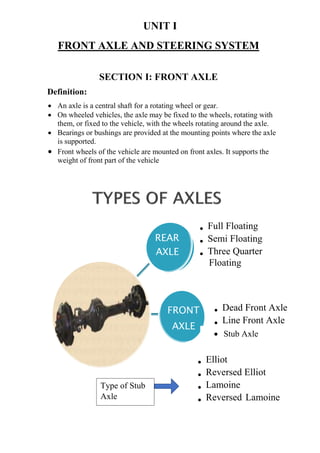
- 1. UNIT I FRONT AXLE AND STEERING SYSTEM SECTION I: FRONT AXLE Definition: An axle is a central shaft for a rotating wheel or gear. On wheeled vehicles, the axle may be fixed to the wheels, rotating with them, or fixed to the vehicle, with the wheels rotating around the axle. Bearings or bushings are provided at the mounting points where the axle is supported. Front wheels of the vehicle are mounted on front axles. It supports the weight of front part of the vehicle REAR AXLE • Full Floating • Semi Floating • Three Quarter Floating FRONT AXLE • Dead Front Axle • Line Front Axle • Elliot • Reversed Elliot • Lamoine • Reversed Lamoine Stub Axle Type of Stub Axle
- 2. FRONT AXLE It facilitates steering. It absorbs shocks, which are transmitted due to road surface irregularities. It absorbs torque applied on it due to braking of vehicle. A) Dead Front Axle : Dead axles are those axles, which donet rotate. These axles have sufficient rigidity and strength to take the weight. The ends of front axle are suitably designed to accommodate stub axle. Stub Axle Main Beam King Pin Track Rod
- 3. B) Line Front Axle : Line axles are used to transmit power from gearbox to front wheels. Line front axles although, front wheels. Line front axles although resemble rear axles but they are different at the ends where wheels are mounted. Maruti- 800 has line front axle. C) Stub Axle : A stub axle, which is provided in the ends of the axle beam of a front axle. Stub axles are connected to the front axle by king pins. Front wheels are mounted on stub axles arrangement for steering is connected to stub axles. Stub axle turns on kind pins. King pins is fitted in the front axle beam eye and is located and locked there by a taper cotter pin. Stub axles are of four types : (a) Elliot (b) Reversed Elliot (c) Lamoine (d) Reversed Lamoine All are differ from each other in the manner in which they are connected to the front axle.
- 4. (a) Elliot Elliot is a type of Stub-Axle, they are connected to the front axle by king pins. Kingpins is fitted in the front axle beam eye and is located and locked there by a taper cotter pin. (b) Reversed Elliot The Stub axle forms the fork end. The Front axle end forms eye . The thrust washer is placed at the bottom of the front axle beam. The cotter pin in the joint locks locks the movement of king pin in the front axle beam. (c) Lamoine The Front axle beam end forms eye to take supports the Stub axle. The Stub axle and King pin are integrated to form L- shape assembly to receive the front axle. The thrust washer is placed at the bottom. The cotter pin in the joint is used to lock the front axle in position . The king pin is free to move (swing or oscillate) in the Phosphor bronze bushes placed in the eye of the front axle . The thrust washer takes the vertical load in the joint . The use of thrust washer increases the life of both the stub axle and front axle
- 5. (d) Reversed Lamoine The Front axle beam end forms eye to take supports the Stub axle. The Stub axle and King pin are integrated to form Inverted L- shape assembly to receive the front axle. The thrust washer is placed at the bottom as shown in the figure. The cotter pin in the joint is used to lock the front axle in position . The king pin is free to move (swing or oscillate) in the Phosphor bronze bushes placed in the eye of the front axle . The thrust washer takes the vertical load in the joint . The use of thrust washer increases the life of both the stub axle and front axle. SECTION II: STEERING SYSTEM STEERING GEOMETRY The term "steering geometry" (also known as "front-end geometry") refers to the angular Relationship between suspension and steering parts, front wheels, and the road surface. Because alignment deals with angles and affects steering, the method of describing alignment measurements is called steering geometry. There are five steering geometry angles : 1) Camber 2) Caster 3) king pin inclination 4) Toe in & Toe-out on turns
- 6. 1) Camber: Camber angle is the angle between the vertical line and centre line of the tyre when viewed from the front of the vehicle. Camber angle is positive when this is outward. This happens when wheels are further apart at top than at bottom. On the contrary, camber angle is negative when angle is inward. This happens when wheels are further apart at bottom than at top. The camber, should not be more than 2 degree, because this causes uneven or more tyre wear on one side than on other side.
- 7. 2) Caster: Caster angle is the tilt of king pin centre line towards front of back from the vertical line. It is the angle between the vertical line and king pin centre line in the wheel plane when looked from side. 3) King pin inclination It is the angle between king pin centre line and vertical line when seen from the front of the vehicle. It is also called steering axle inclination. King pin inclination and caster are used to improve directional stability in cars. This is also used to reduce steering effort when steering a stationary It reduces tyre wear. This inclination varies from 4 to 8 degree in modern cars.
- 8. 4) Toe In & Toe Out In automotive engineering, toe also known as tracking. This can be contrasted with steer, which is the anti symmetric angle, i.e. both wheels point to the left or right, in parallel (roughly). Positive toe, or toe in, is the front of the wheel pointing in towards the centreline of the vehicle Negative toe, or toe out, is the front of the wheel pointing away from the centreline of the vehicle.
- 9. ACKERMANN STEERING GEOMETRY Ackermann steering geometry is a geometric arrangement of linkages in the steering of a car or other vehicle designed to solve the problem of wheels on the inside and outside of a turn needing to trace out circles of different radii. Modern cars do not use pure Ackermann steering partly because it ignores important dynamic and compliant effects. The use of such geometry helps reduce tyre temperatures during high- speed cornering but compromises performance in low speed maneuvers. The intention of Ackermann geometry is to avoid the need for tyre to slip sideways when following the path around a curve. As the rear wheels are fixed, this centre point must be on a line extended from the rear axle. Intersecting the axes of the front wheels on this line as well requires that the inside front wheel is turned, when steering, through a greater angle than the outside wheels.
- 10. Mechanism : Ackermann steering geometry is a geometric arrangement of linkages in the steering of a car or other vehicle designed to solve the problem of wheels on the inside and outside of a turn needing to trace out circles of different radius. When the vehicle moves along straight path, the longer links AB and CD are parallel and the shorter links BC and AD are equally inclined to the longitudinal axis of the vehicle. When the vehicle moves left, the position of the gear is shown by dotted lines in figure. Derivation :
- 12. DAVIS STEERING
- 13. This is an exact steering gear mechanism. This mechanism fulfils the above steering condition. But due to presence of more sliding members, the wear will be increased and this eliminates the accuracy.
- 14. Difference between Ackermann and Davis Mechanism
- 15. LAYOUT OF A STEERING SYSTEM A typical steering system consists of Steering wheel Steering shaft Steering gear box Pitman arm Drag link Steering knuckle arm Tie rod Track rod arm STEERING GEAR BOXES : Steering gears are used to reduce the steering effort and convert rotary motion of steering wheel into straight line motion of linkage. Thus, steering gear provides mechanical advantage also to make steering easy. Steering gears are put inside the steering gear box. Steering gear box connects steering shaft and steering linkages. Various types of steering gears used in different automobiles are listed below : 1) Worm and sector type. 2) Worm and worm wheel type. 3) Worm and roller type. 4) Rack and pinion type. 5) Cam and roller type.
- 16. 1. Worm and Sector Type Steering Gear : In a worm and sector type steering gear a worm is provided at the end of steering shaft which meshes with a sector provided on a sector shaft. When the worm is rotated, the sector turns which moves the linkages for steering the vehicle. The sector shaft is also called pitman arm shaft, roller shaft or cross shaft. Worm and sector are based on the principle of transmitting the motion from the steering tube to the Pitman arm. The worm is attached with the inner column of the bearing block. The box is connected to the level of the plug with normal gear oil for lubrication of the steering gear. The worm at the end of the steering shaft meshes with a sector mounted on a sector shaft. When the steering wheel is rotates, then the worm will rotates.
- 17. 2. Worm and Worm Wheel Type Steering Gear : There are square threads or worms on the steering rod end which engages in a worm wheel. Worm wheel is connected to a drop arm. When driver rotates the steering wheel, drop arm moves forward or backward resulting in motion of stub axle. The arc movement of the drop arm is usually from 60 to 90 deg. This system is commonly used in tractors. A square shaft is generally used on which worm wheel is mounted.
- 18. 3. Worm and Roller Type Steering Gear : In the worm and roller steering gear, a roller with two teeth is meshes with the teeth on roller. This type of system was popular in American passenger cars. Worm and roller gear have two-toothed roller which are fastened to the cross shaft called as roller shaft or sector shaft. The threads of the worm gear are meshed with roller shaft at the end of the steering tube. When the worm shaft is turned by the steering tube, the roller will also be moved in an arc for rotating the roller shaft. The bearings are designed to resist both radial and end thrust.
- 19. 4. Rack and Pinion Steering Gear A pinion is attached at the end of the steering shaft. A rack mashes with the pinion. The rotary movement of the steering moves the pinion which gives motion to the rack. The movement of the rack is responsible for turning the wheels through steering linkages. Construction: This type of steering gear is mainly used in cars having independent front suspension. The pinion is mounted at the end of the steering shaft. A universal joint is connected at the bottom end of the steering shaft to mount the steering box centrally. A rack is engaged with the pinion. The rack reciprocates sideways to give lateral movement to the front wheels. Spring pads connected with the rack reduce the backlash between gears to a minimum.
- 20. 5. Cam and Roller Construction The cam and roller steering boxes are very efficient. The cam is carried by the steering shaft connected with rollers. The drop arm spindle carries the vee shaped roller. This spindle is carried by ball bearings in the casing. The meshing member contains the spiral grooves. The centre position of the pin supports the roller.
- 21. Working : By moving the steering wheel and steering shaft, the cam is rotated. Due to this rotation, the roller is constrained to follow the helix of the groove. When the cam rotates, the roller is followed the cam and made the rocker shaft to rotate. The contour of the cam is properly designed to match with our aim.