
Recommended
More Related Content
What's hot
What's hot (20)
Viewers also liked
Viewers also liked (12)
Similar to Construction Surveys Chapter
Similar to Construction Surveys Chapter (20)
More from Est
More from Est (20)
Recently uploaded
Recently uploaded (20)
Construction Surveys Chapter
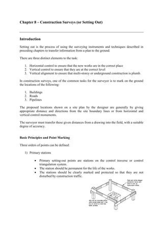
- 1. Chapter 8 – Construction Surveys (or Setting Out) Introduction Setting out is the process of using the surveying instruments and techniques described in preceding chapters to transfer information from a plan to the ground. There are three distinct elements to the task: 1. Horizontal control to ensure that the new works are in the correct place 2. Vertical control to ensure that they are at the correct level 3. Vertical alignment to ensure that multi-storey or underground construction is plumb. In construction surveys, one of the common tasks for the surveyor is to mark on the ground the locations of the following: 1. Buildings 2. Roads 3. Pipelines The proposed locations shown on a site plan by the designer are generally by giving appropriate distance and directions from the site boundary lines or from horizontal and vertical control monuments. The surveyor must transfer these given distances from a drawing into the field, with a suitable degree of accuracy. Basic Principles and Point Marking Three orders of points can be defined: 1) Primary stations • Primary setting-out points are stations on the control traverse or control triangulation system. • The station should be permanent for the life of the works. • The stations should be clearly marked and protected so that they are not disturbed by construction traffic.
- 2. 2) Secondary stations • Secondary setting-out points are established closer to points of detail on the proposed works, and are referenced by measurement from the primary points. 3) Detail points • Detail points mark (e.g. 50mm square timber peg with a nail in the top) the location of features on the works such as the centre of a pile, or the corner of a building. Accuracy Table below shows the expected accuracy for equipment in good working condition and adjustment as recommended in BS5606:1990 Code of Practice for Accuracy in Building. * EDM is not recommended for distances less than 30m, where a steel tape used with precision is more accurate.
- 3. Building and Pipeline Stakeout Stakeout of new buildings and underground pipelines Traditional procedures: baseline offsets and batter boards Staking out a building Property survey must precede the stakeout of any structure on a parcel of land to accurately locate boundary lines. Building lines (or building setbacks) specified in the local building code must be located. A setback is the minimum required distance between a new building and a front or side property line. Staking out a building makes use of several perpendicular offsets measured from a predetermined baseline. The baseline serves as a reference to control the position of the proposed structure (it may be a property line).
- 4. Batter Boards (or Profile Boards) A standard method for temporarily referencing the building corners makes use of the batter board. A batter board is simply a horizontal wooden plank fastened to two vertical posts. *The land surveyor may be required only to set offset stakes at each corner of the building and to set a benchmark. *The builder is then generally responsible for setting up the batter boards using the land surveyor’s reference marks.
- 5. A pair of batter boards are built offset from each corner so that opposite boards will support a wire, string, or carpenter’s line. The string lines are stretched taut between two nails driven into the tops of opposite boards, which are usually set at the same elevation so that the line will be level. The string lines then establish both line and grade. The intersection of two strings marks the position of a corner and this position is easily transferred vertically with the plumb-bob cord. The string lines can be removed so not to interfere with the work, and then replaced as necessary to again give line and grade. Layout Procedure for a simple rectangular structure
- 6. 1. Set up an instrument at monument P a. take line on Q b. set stakes at A and B. 2. Set up an instrument at A a. back-sight on Q b. turn 90° c. set stakes at corners L and M d. set batter boards and nails at 1 and 2. 3. Set up an instrument at B a. back-sight on Q b. turn 90° c. set stakes at corners N and O d. set batter boards and nails at 3 and 4. 4. Measure diagonals LO and NM and check with length computed using the Pythagorean theorem; re-stake if necessary 5. Set up an instrument at L a. back-sight on N b. set nail 5 c. plunge scope and set nail 6 6. Set up an instrument at M a. back-sight on O b. set nail 7 c. plunge scope and set nail 8
- 7. Line and Grade for a Sewer Flow in a storm sewer or in a sanitary sewer is called open channel gravity flow. The flow capacity of a given diameter pipe depends primarily on the slope or gradient of the flow line. The flow line (or invert) is the bottom inside surface of the pipe or drainage channel. Whenever the pipeline changes in slope, diameter or direction, a manhole is built to provide access both for sewage flow measurement and sampling and for pipeline inspection and maintenance. Batter boards have traditionally been used to give line and grade for a gravity flow pipeline (lasers are frequently used in present-day construction). The pipe is first located by a series of stakes that are usually set at 50ft (15m) intervals and offset 3 – 6 ft (1 – 2m) from the pipe centerline. The batter boards are set at a constant elevation (say, 7’0”) above the pipe flow line or invert and a string line is run between the boards so that it is directly over the pipe centerline. The string line will have a slope equal to that of the pipeline.
- 8. It is then simple for the workers to place the pipe sections into the trench in the proper position on a bed of sand and gravel, and to adjust the pipe invert while making periodic measurements from the string line.
- 9. Example Suppose that it is necessary to build a new sewer from a house to an existing manhole. It is assumed that the flow line must be at least 3ft (1m) below the ground surface, and the minimum slope should be 0.004. A manhole should be placed at any change in gradient. The flow line elevation at the house is given as 70.03 on the plans. The invert elevation of the existing manhole must be determined during the preliminary survey by opening the manhole cover and observing a rod held on the flow line. Field steps: 1. Stake out a 4-ft offset line, placing stake 0+0 beside the point in the house where the house connection is located and a stake every 50 ft thereafter. Carry the measurement to a point beside the manhole, and determine its plus. 2. Find the elevation of the ground at each 50 ft point along the true line and at all breaks in ground slope. The rod is held on the ground at an estimated 4 ft from and opposite to each offset stake. This places the rod at the true position on the construction line. 3. At the same time, determine the elevation of the tops of each of the offset-line stakes. 4. Draw the profile of the ground elevations and determine the grade profile for the flow line.