1. Variable Air Volume Systems
https://www.youtube.com/watch?v=YCogTVa3XOw
Description:
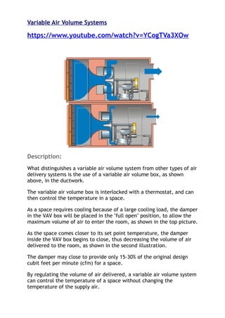
What distinguishes a variable air volume system from other types of air
delivery systems is the use of a variable air volume box, as shown
above, in the ductwork.
The variable air volume box is interlocked with a thermostat, and can
then control the temperature in a space.
As a space requires cooling because of a large cooling load, the damper
in the VAV box will be placed in the "full open" position, to allow the
maximum volume of air to enter the room, as shown in the top picture.
As the space comes closer to its set point temperature, the damper
inside the VAV box begins to close, thus decreasing the volume of air
delivered to the room, as shown in the second illustration.
The damper may close to provide only 15-30% of the original design
cubit feet per minute (cfm) for a space.
By regulating the volume of air delivered, a variable air volume system
can control the temperature of a space without changing the
temperature of the supply air.
2. There are several variations on the traditional VAV system, including
VAV boxes with fans and heating coils.
These variations were created to counteract some of the negative
effects of a traditional VAV system, which will be discussed below.
VAV System Schematic
The graphic above outlines the major components included in a
variable air volume system.
The above diagram shows the air handling unit, which includes the
mixing box, filter, heating and cooling coils, fan, and the ductwork.
In addition to the air handling unit, the illustration shows the VAV
box and the diffuser.
All of these elements will be discussed below.
In addition to the components shown above, the VAV system also
used chilled water and hot water in the coils to accomplish heating
and cooling.
Chillers, boilers, and heat exchangers provide the mediums required
for heating and cooling.
3. A description of these components can be found on the HVAC
components page of this website.
Air Handling Unit:
The air handling unit is the location where air is conditioned to an
acceptable level for distribution within the building.
An air handling unit is composed of several components and
subsystems, defined as follows:
1. Mixing Box: The mixing box is the location where return air
and outdoor air are mixed to satisfy outdoor air
requirements set forth in the ASHRAE standards.
2. Filter: The filter removes particulates from the air. The
amount and size of particulates removed depends on the
rating of the filter.
3. Cooling Coil: The cooling coil cools the air to the desired
temperature. In addition to cooling the air, moisture is
removed from the air in a dehumidification process based on
the properties of air.
4. Heating Coil: The heating coil can have a hot water or steam
medium. The primary purpose of this coil is to heat the air
to a required temperature.
5. Humidifier: A humidifier adds moisture to the air in the
heating mode, if required. Humidifiers are commonly served
by a steam manifold.
6. Fan: The fan pressurizes the air so it can travel through
the ductwork to the space requiring the air.
7. Ductwork: The ductwork serves as a pathway for the
transportation of the air from the air handling unit to the
space.
Diffuser:
4. The diffuser is the component of the system that ultimately
delivers the air to the space.
A diffuser regulates velocity of the entering air, throw pattern, and
volume of entering air through the use of an integral volume damper.
In VAV systems, linear slot diffusers are usually preferred to
traditional square diffusers.
Since linear slot diffusers have a plenum attached to the register,
they can more evenly distribute air at times when the delivered air
volume is low.
If a traditional square diffuser is used on a VAV system, a
"puddling" effect often occurs where the cold air just drops to the
floor, instead of being circulated around the room.
VAV Box Components:
VAV Box with Inlet and Actuator
5. Casing: See diagram above for description.
Inlet: The inlet is a round connection to the VAV box from the
often square supply ductwork.
Damper: The damper is a component which can open or close to vary
the volume of air passed through the VAV box.
Damper Shaft: The damper shaft is the operational tool that allows
the damper to open or close. The shaft is connected to a motor
(actuator), which is interlocked with the room thermostat.
Fan: A fan is a component of a fan powered VAV box, which is not
shown above. The fan helps to improve air velocity during times of
low volumetric flow rates.
6. Reheat Coil: A heating coil can be added to a VAV box to improve
air volume and velocity when a room nears its design temperature.
Thermostat: The thermostat is placed within the space and allows
the occupant to control the temperature. The thermostat is
interlocked with the damper shaft to control the position of the
damper.
Types of VAV Systems:
Traditional: A traditional VAV system consists of a VAV box with a
damper to control the volume of air delivered to a space. When the
space approaches design conditions, the damper may close to provide
only 15% of the design cfm.
Fan Powered VAV: The addition of a fan to a VAV box improves air
movement at times when a space is near its design temperature and
supply air volumes are low. The fan will usually be set to begin
running when the damper is 50% closed. The addition of a fan,
however, reduces the efficiency of the system because the fan
motor requires electric input for power.
VAV with Reheat: A reheat coil (hot water or electric) can be
added to a VAV box to improve air volume and movement when a
space approaches design temperature. When the damper closes to a
determined position (usually 50% of the design cfm), the reheat coil
becomes operational and heats the air. Since the supply air is now
warmer, a larger amount will have to be delivered to the space, which
improves the volume of air and velocity.
Advantages of a VAV System:
1. Efficiency
A variable air volume system is highly efficient because the minimal amount
of air required is used to keep a space at its design temperature. When the
damper closes in a VAV box, the fan in the air handling unit can run at a
slower speed (through the use of a variable speed drive) and the amount
heating and cooling mediums running through the coil can be reduced
7. (through electric or pneumatic control valves). In essence, a VAV system
allows the air handling unit, chillers, and boilers to run a part load, which is
more efficient.
2. Individual Temperature Control
Since a VAV box is linked to a thermostat, the ability to control temperature
in a space is independent of other spaces. Rooms with similar loading
patterns are often placed on the same VAV box, and through the use of a
VAV system, areas with very different loading patterns can be placed on the
same air handling unit.
3. Cost
VAV systems are very cost effective in operation, but also offer a fairly low
first cost. Since traditional VAV systems do not require piping or coils, they
are cheaper to install and require simple electrical installation.
4. Flexibility
VAV systems are highly flexible because the boxes can easily be removed
from one ductwork branch and placed into another, assuming that the design
cfm for the spaces are similar.
Disadvantages of a VAV System:
1. Air Velocity at Design Conditions
As a VAV system reaches its design set point, the volume of air delivered to
a room is decreased. This decrease in air volume is a problem because the
outdoor air requirements of 20 cfm/person are not met, the velocity of air is
decreased resulting in discomfort, and if a space requires positive pressure
the needs cannot be met with a VAV system. To combat this trend, the
addition of a fan or heating coil to the VAV box can alleviate many of these
problems, however there is a greater expense involved.
2. Space Requirements
The installation of a VAV box requires considerable space, both in the
vertical and horizontal directions. As a rule of thumb, the linear duct length
before a VAV box should be three times the diameter of the inlet. This
length is required for the air profile in the duct to even out before entering
the box. In the vertical direction, the VAV box can require up to 18", which
can be a problem if above ceiling heights are relatively small.
3. Inability to Simultaneously Heat and Cool
In many building situations, it is common to require heating in some parts
(usually at the perimeter) and cooling in others (usually interior). Since a
traditional VAV system does not have a heating coil in the box, heating in one
space and cooling in another cannot take place. This problem can be overcome
by adding a coil to the VAV box.
8. 4. VAV Box Location
Since VAV boxes must be located in the branch ductwork, they are often
placed above the ceiling. In situations where an acoustical ceiling is used,
there is easy access to the box. However, in situations where a plaster
ceiling is present, an access panel must be provided to allow access to the
box.
Typical Uses For a VAV System:
1. Offices
VAV systems are commonly used in offices because of their
efficiency and ability to grant independent temperature control.
A VAV system is also rather flexible, as the boxes can easily be
moved into new ductwork branches to accommodate office
renovations. Offices are usually not as pressure sensitive as other
scenarios (such as hospitals or laboratories), so the deficiencies
in pressure associated with a VAV system are not a large concern.
2. Auditoriums
VAV systems work well in auditoriums because these spaces are
occupied at intermittent intervals. When the space is occupied,
the damper in the VAV box is completely open to combat the
cooling load. However, when the auditorium is not in use, the
dampers will be mostly closed, allowing the rest of the mechanical
system to run at part load.
3. Stores
VAV systems are commonly used in stores because of their
efficiency. Since a store might have occupancy only 8 hours of
the day, having the mechanical system running at part load for
the unoccupied hours can provide quite a savings. In addition,
pressurizing issues are not as important in stores as in other
cases.
9. Inappropriate Uses for a VAV System:
1. Laboratories/Hospitals
Traditional VAV systems would not be a good choice to use in a
situation where pressurizing spaces is critical. For instance, a
hospital hallway serving isolation rooms must be positively
pressured so that contagious germs do not seep out of the
isolation room. Since a traditional VAV system cannot assure a
constant volume of delivered air, it works poorly in positively
pressured situations.
Numerical Parameters:
1. Dimensions
A VAV box passing a maximum of 250 cfm will measure
16"x10"x10" (LxHxW)
A VAV box passing a maximum of 8000 cfm will measure
28"x17.5"x32" (LxHxW)
2. Duct Length Requirements
A straight duct length equal to three times the inlet diameter is
required for the proper installation of a VAV box.
3. Hot Water Coil Capacities
Heating MBH of a hot water coil is based on the amount of air
being passed over the coil, the temperature of the hot water, and
the flow rate of the water through the coil. For a 0.5 gpm flow
rate serving a 75 cfm box, the heating capacity is 4.9 MBH. For a
4.0 gpm flow rate serving a 500 cfm box, the heating capacity is
20 MBH.
10. 4. Fan Motor Size
If choosing to add a fan to the VAV box, the horsepower of the
fan motor depends on the cfm of the box. For 250 cfm, a 1/6
horsepower motor is appropriate, while a 3/4 horsepower motor
would be required to move 4200 cfm.
5. Damper Position
The damper in a VAV box may close enough to only provide 15% of
the design volumetric flow rate.