This document discusses tool wear in machining. It defines tool wear as the gradual failure of cutting tools due to regular operation. There are three main modes of tool failure: fracture failure from excessive forces, temperature failure if the tool gets too hot, and gradual wear over time. Factors that influence the rate of tool wear include the tool material, workpiece material, cutting dimensions/speed, tool geometry, temperature, and cutting fluid used. The main types of tool wear are crater wear on the rake face, flank wear along the tool edge, and corner or nose wear which shortens the cutting edge. Controlling tool wear involves reducing the cutting temperature through fluids/lubricants or advanced tool materials.
2. Introduction: Tool Wear
Wear is loss of material on an asperity or micro-
contact, or smaller scale, down to molecular or
atomic removal mechanisms. It usually progresses
continuously.
Tool wear describes the gradual failure of cutting
tools due to regular operation.
It is a term often associated with tipped tools, tool
bits, or drill bit that are used with machine tools.
Gradual failure of cutting tools due to regular
operations is also known as tool wear.
Tool failure implies that the tool has reached a
point beyond which it will not function satisfactorily
until it is re-sharpened.
Dr. Jayanta Kr. Mahato, Asst. Prof., Mechanical Engineering2
3. Modes of cutting tool failure
FRACTURE FAILURE:
□This mode of failure occurs due to mechanical breakage due to
excessive forces and shocks at the tool point causing it to fail suddenly by
brittle fracture.
Also known as mechanical chipping.
□Such kind of tool failure is random and catastrophic in nature, results in
premature loss of tool and hence is extremely detrimental.
TEMPERATURE FAILURE:
□This failure occurs when the cutting temperature is too high for the tool
material, causing the material at the tool point to soften, which leads to
plastic deformation and loss of the sharp edge.
□This type of failure also occurs rapidly, results in premature loss of tool
and is quite detrimental and unwanted. Note: Both of the above kinds of
tool failure need to be prevented by using suitable tool materials and
geometry depending upon the work material and cutting condition.
GRADUAL WEAR:
Gradual wearing of the cutting edge causes loss of tool shape, reduction
in cutting efficiency, an acceleration of wearing as the tool becomes
heavily worn, and finally tool failure in a manner similar to a temperature
failure.
Gradual wear is preferred because it leads to the longest possible use of
the tool, option of changing the tool before the final catastrophic loss of
the cutting edge occurs, with the associated economic advantage of that
longer use.
4. Ways of measuring tool life
Number of pieces of work machined.
Total volume of material removed.
Total length of cut.
Limiting value of surface finish.
Increase in cutting forces.
Dimensional accuracy.
Overheating and fuming.
Presence of chatter.
Dr. Jayanta Kr. Mahato, Asst. Prof., Mechanical Engineering
5. Tool wear depending factors
1. Type of tool material and its hardness
2. Type and condition of work piece material
3. Dimensions of cut (Feed and depth of cut)
4. Cutting speed
5. Tool geometry
6.Tool temperature (function of cutting speed,
feed and depth of cut)
7. Type of cutting fluid
Dr. Jayanta Kr. Mahato, Asst. Prof., Mechanical Engineering5
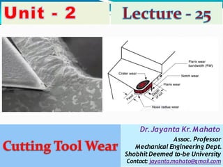
6. Classification of tool wear
The tool wares are classified into the following types:
1. Crater wear on tool face
2. Flank wear
3.Localized wear such as the rounding of Cutting edge
(Nose wear/Corner wear)
4. Chipping of the cutting edge
7. Crater Wear
It consists of a cavity or concave section
on the tool face/rake face formed and
grows from the action of the chip sliding
against the surface.
High stresses and temperatures
characterize the tool–chip contact
wearing
interface, contributing to the
action.
The crater can be measured either by its
depth or its area.
Crater wear affects the mechanics of the
process increasing the actual rake angle
of the cutting tool and consequently,
making cutting easier.
At the same time, the crater wear
weakens the tool wedge and increases
the possibility for tool breakage.
This wear predominates at high speed. In
general, crater wear is of a relatively
small concern.
8. Causes of Crater Wear
The crater wear is mainly
caused due to:
□The presence of friction
between the chip-tool interface,
□The abrasion action of
microchips present at the chip-
tool interface.
□The abrasive action of
fragments of Built up Edge (BUE)
at the chip-tool interface and
diffusion wear.
□The diffusion wears, due to the
atomic attraction between the
tool and work the atoms of the
tool material will get diffused and
deposited over the work piece
called diffusion wear.
9. Flank Wear
It occurs on the tool flank as a result of friction between
the machined surface of the work piece and the tool flank.
Flank wear appears in the form of so-called wear land and
is measured by the width of this wear land, VB.
Flank wear affects to the great extend the mechanics of
cutting.
An extreme condition of flank wear often appears on the
cutting edge at the location corresponding to the original
surface of the workpart. This is called notch wear. It
occurs because the original work surface is harder and/or
more abrasive than the internal material, which could be
caused by work hardening from cold drawing or previous
machining, sand particles in the surface from casting, or
other reasons. As a consequence of the harder surface,
wear is accelerated at this location.
Cutting forces increase significantly with flank wear. If the
amount of flank wear exceeds some critical value (VB >
0.5~0.6 mm) then the excessive cutting force may cause
tool failure.
This wear predominates at low speed.
10. Causes of Flank Wear
work
The flank wear is mainly caused due to:
□ The presence of friction at the tool
interface.
□The abrasive action of microchips or powdered
particles present at the tool work interface and
diffusion wear.
□The diffusion wears, due to the atomic
attraction between the tool and work the atoms
of the tool material will get diffused and
deposited over the workpiece called as diffusion
wear.
Dr. Jayanta Kr. Mahato, Asst. Prof., Mechanical Engineering10
11. Corner wear or nose Wear
It occurs on the tool corner.
□It can be considered as a part of the wear land and
respectively flank wear since there is no distinguished
boundary between the corner wear and flank wear land.
□We consider corner wear as a separate wear type
because of its importance for the precision of machining.
□Corner wear actually shortens the cutting tool thus
increasing gradually the dimension of machined surface
and introducing a significant dimensional error in
machining, which can reach values of about 0.03~0.05 mm.
14. Control of Tool Wear
The rate of tool wear strongly
depends on the cutting
temperature; therefore any
measures which could be
applied to reduce the cutting
temperature would reduce the
tool wear as well.
Use of cutting fluids,
lubricants is another method.
Additional measures to reduce
the tool wear include the
application of advanced
cutting tool materials, such as
coated carbides, ceramics,
etc.
The figure shows the process
parameters that influence the
rate of tool wear:
Dr. Jayanta Kr. Mahato, Asst. Prof., Mechanical Engineering