1. EJEMPLO:
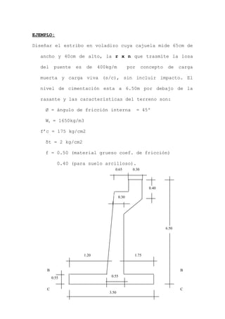
Diseñar el estribo en voladizo cuya cajuela mide 65cm de
ancho y 40cm de alto, la r x n que trasmite la losa
del puente es de 400kg/m por concepto de carga
muerta y carga viva (s/c), sin incluir impacto. El
nivel de cimentación esta a 6.50m por debajo de la
rasante y las características del terreno son:
Ø = ángulo de fricción interna = 45º
Ws = 1650kg/m3
f’c = 175 kg/cm2
δt = 2 kg/cm2
f = 0.50 (material grueso coef. de fricción)
0.40 (para suelo arcilloso).
3.50
0.55
1.20 1.75
0.55
B
C
B
C
6.50
0.30
0.65 0.30
0.40
2. T = H/12 = 6.50/12 = 0.54 ≈ 55 cm
A = H/12 = 55 cm
B = H/2 ó 2H/3
6.50/2 = 3.25
Hacemos B = 3.50
B/3 = 1.17 ≈ 1.20
CARGAS:
- EMPUJE ACTIVO:
H’ = 0.61m = 1000/1650
Ea = 7079 kg.
F = 0.15R = 0.15 x 4000 = 600 kg.
YF = 6.50 – 0.40 + 0.025 = 6.125
C = 1 – Sen 45º = 0.171
1 + Sen 45º
Ea = cwh (h + 2h’)
2
Ea = 0.717 x 1650 x 650 ( 6.5 + 2 x 0.61)
2
y = h(h + 3h’) = 6.5(6.5 + 3 x 0.61) = 2.33 m.
3(h + 2h’) 3(6.5 + 2 x 0.61)
3. VERIFICACIÓN DE ARRANQUE:
MOMENTO FLECTOR EN EL ARRANQUE:
M = Ea y + F YF = 6018 x 2.15 + 600 x 5.575
YF = 5.95 – 0.40 + 0.025 = 5.575
MA = 16284 kg-m
W = S/C = 0.61, W = 1006.5
Eab = 0.171 x 1650 x 5.95 (5.95 + 2(0.61)) = 6018kg
2
Yb = 5.95(5.95 + 3 x 0.61) = 2.15
3(5.95 + 2 x 0.01)
0.55
0.40
S/C
T2
2.15 = y
0.55
Ea
T3
T1
W2
W1
3.50
1.20 1.75
0.55
B
C
B
C
5.95
0.30
0.65 0.30
F
0.65
se considera.
YF
4. CORTANTE EN EL ARRANQUE
V = Ea + F = 6018 + 600 = 6618 kg
- ESPESOR EN EL ARRANQUE
Rb
M
d = Flexión
fc = 0.45f’c = 780.75 kg/cm2
fs = 0.5 fy = 2100 kg/cm2
Es = 2.1 x 10⁶
Ec = 15000 cf’c
J = 1 – R/3 = 1 – 0.273/3 = 0.909
R = (fc j k)/2 = 9.77, b = 100cm
cm
x
d 41
10077.9
1628400
==
ANCHO MÍNIMO EN ARRANQUE
d = 7cm = 41 cm + 7 = 48 cm.
= 48cm < 55cm OK!
n = 2.10 x 106
= Es = 10.5
15000√175 Ec
R = 1 = 0.273
1 + Fs .
n fc
5. POR CORTE
bd
v
=υ cfmax '3.0=υ se considera así:
v/bd = 0.3√f’c luego, d = v/(0.3b√f’c)
d = 6618/(0.3 x 100√175) = 16.7cm < 55 OK!
ESTABILIDAD:
Sección C - C’
a) Estribos sin puente y relleno S/C
VOLTEO
W1 = 0.50 x 0.40 x 2.4 = 0.288
W2 = 0.65 x 0.65 x 2.4 x 0.5 = 0.507
W3 = 5.55 x 0.30 x 2.4 = 3.996
W4 = 4.90 x 0.25 x 0.5 x 2.4 = 1.470
W5 = 3.50 x 0.55 x 2.40 = 4.620
T1 = 5.95 x 1.10 x 1650 = 10.799
T2 = 0.65 x 0.65 x 0.5 x 1.65 = 0.348
T3 = 4.90 x 0.45 x 1.65 = 2.235
S/C = 1.10 x 1006.5 = 1.107
28.390
8. ESFUERZOS TRASMITIDOS
.
δmax = 1.34> 2 OK!
δmin = 0.52> 2 OK!
DISEÑO DE LA PANTALLA: (Cálculo del acero)
d = 55 – 7 = 48
Ø 5/8” (2cm2) = 1 Ø5/8” @ 11cm
Ø 3/4” (2.85cm2) = 1 Ø3/4” @ 16cm
CHEQUEO POR ADHERENCIA
E0 nec = V/(Mjd) = 6618/(15.97 x 0.909 x 48) = 9.50cm
E0 Mu = 9.5
Ø 3/4” = 5.98cm
Eo disponibilidad de 1m de c/muro:
(100/16 + 1)(5.98) = 41.86 > 9.5 OK!
δ = 0.01 x 32390 ± 0.06 x 32390 x 0.26 = 0.93 ± 0.41
3.50 3.502
As = Ms .
fs j d
As = 16284.00 = 17.77 cm2/metro de muro
2100 x 0.909 x 48
M = 2.3√f’c = 2.3√175 = 15.97
D ¾ x 2.54
9. LONGITUD DE DESARROLLO:
ACERO DE REPARTO
Acero repar. Vert.
= 0.0015 x 100 x 48 = 7.2 cm2 Ø5/8” @27 ó Ø 1/5” @ .
Acero repar. Horiz.
= 0.0025 x 100 x 48 = 12 cm2 Ø5/8” @17
Lsd = Fs D = 2100 x 1.587 = 52cm (anclaje en ciment.)
4u 4 x 15.97
s
S2
Ø 1/2" @ 17
Ø 5/8” @ 17
10. DISEÑO DE REPARTO:
CASO I
W = pr + pp + S/C
W = 1650 x 5.95 + 2400x 0.5 + 1000
W = 12017.50 kg/m2
σmin = 0.76
σmax - σmin = 0.10
a/1.75 = 0.10/3.50 ; a = 0.05
σa = 0.810
b/2.3 = 0.10/3.50 ; b = 0.066
σb = 0.826
CÁLCULO DEL MOMENTO EN EL INICIO DEL TALÓN (D)
1.20 0.55 1.75
2.05 1.545
a
σmax=0.86
C
D
l
E
B
A
W
σmin = 0.76
MD = W l2
– l2
(2σmin + σa = 1 l2
(w – 2(σmin + σa))
2 6 2 6
11. - CORTANTE A UNA DISTANCIA d/2
= (48 – 7)/2 = 0.804
σa = 0.76 + (0.1 x 1.545)/3.5 = 0.804
V = w l2
– (σa2
- σmin)l2
/2
= 12017.5 x 1.545 – 0.5 (7600 + 8040)1.545
= 18567.037 – 12081.9 = 6485.14 = 6485
CASO II
σmin = 0.520 kg/cm2 = 5200 kg/m/m de ancho
σmax = 1.340 kg/cm2 = 13400 kg/m/m de ancho
σa = 0.520 + 1.75 (1.34 – 0.52)/3.50 = 0.92510 kg/cm2
= 9210 kg/m por metro de ancho
- CORTANTE
V = 12017.5 X 1.5454 – 0.5(8820 + 5200) = 11557 kg-m
MD = 1 x l.752
(12017.5 – (2 x 7600 + 8100)) = 12455 kg-m
2 6
MD = 1 x l.752
(12017.5 – (2 x 5200 + 93100)) = 13397 kg-m
2 6
σa = 0.520 + 1.545(1.34 – 0.52) = 0.882
350
12. DISEÑO DEL ACERO DEL TALÓN
Utilizamos los valores más encontrados: (esfuerzos de
trabajo).
VERIFICACIÓN DEL PERALTE
cm
x
x
Rb
M
d 70.35
10077.9
10012455
===
Tomamos: d = 48 – 7 = 41 OK!
CÁLCULO DEL ACERO
Utilizamos dc = 10cm, d = 40
As = 16.31 cm2 <> Ø 5/8” 1.98cm2 1 Ø3/8” @ 11.2cm
CHEQUEO POR ADHERENCIA
LONGITUD DE DESARROLLO
Ld = fs D/4u = (2100 x 5/8 x 2.54)/(4 x 19.17) = 43.5 cm
ΣNEC = V con u = 2.3√f’c = 2.3√175 = 19.17
u j d D (5/8 x 2.54)
As = M = 12455 x 100 = 16.31 cm
fs j d 2100 x 0.909 x 40
ΣNEC = 11557 = 16.58 cm
19.17 x 0.909 x 40
Σdisp = ( 100 + 1 )π (1.59) = 49.57 cm >> 16.58 cm OK!
11.2
13. ARMADURA DE REPARTO
As min = 0.0015 x 48 x 100 = 7.2 cm2
As rep y temp = 0.0025 x 48 x 100 = 12cm2
0.0015 x 48 x 100 = 7.2 cm2
DISEÑO DE LA JUNTA
Cargas verticales: sólo pasó propio de base hacia abajo
y r x n del terreno hacia arriba, no se considera empuje
pasivo.
W = 0.55 x 2400 = 1320 kg/cm2
CASO A:
σmax = 0.860 kg/cm2
σb = 0.826 kg/cm2 (calculado en talón)
σmin = 0.760 kg/cm2
MOMENTO:
M = Wl2
/2 - l2
/6 (2σmax + σb)
= 1320 1.202
/2 - 1.202
/6 (2 x 8600 + 8260) = -5160.40
M = -5160.4
CORTANTE:
d/2 = 40/2 = 20 l’ = 1.20 – 0.20 = 1.00
σb’ = 0.760 + (0.86 – 0.76)(3.5 – 1)/3.5 = 0.831
14. V = 1320 x 1.0 – 0.5(8600 + 8310) x 1.00 =
V = -7135.0 kg (hacia arriba)
CASO B:
σmax = 1.345 kg/cm2
σb = 0.52 + 1.0 x (1.34 – 0.52)/3.5 = 0.754 kg/cm2
σmin = 0.52 kg/cm2
MOMENTO:
M = w l2
/2 - l2
/6 (2σmax + σb)
M = 1320 x 1.202
/2 – 1.202
/6(2 x 13400 + 7540)
= -7291.20 (hacia arriba)
CORTANTE:
σb’ = 0.52 + (1.34 – 0.52)(3.5 – 1)/3.50 = 1.106
V = 1320 x 1 – 0.5(13400 + 7540)
= -9150 kg (hacia arriba)
VERIFICACIÓN DEL PERALTE:
cm
x
x
d 403.27
100977
1007291
<== (adoptado)
CHEQUEO POR CORTE TALÓN
d = V/(0.32b√f’c) = 11557/(0.3 x 100√175) = 29.1
15. = 29.41 < 40 OK!
CHEQUEO POR CORTE TALÓN
d = 9150/(0.32 x 100√175) = 23.05 < 40cm OK!
REFUERZO PRINCIPAL:
As = M/fs j d = (7291 x 1000)/(2100 x 0.909 x 40)
= 9.55 cm2 <> Ø 1/2" = 1 Ø 1/2" @ 0.13
Asmin = 0.0015 x 48 x 100 = 7.2cm2 < 9.55 OK!
Asrepart = 0.00025 x 48 x 100 = 12.0cm2 <> Ø1/2” @0.10
CHEQUEO POR ADHERENCIA:
u = 2.3√175/1.27 = 23.96
∑nec = 11557/(23.96 x 0.909 x 40) = 13.26
Edisp = (100/10 + 1)π x 1.27 = 43.9 > 13.26 OK!
LONGITUD DE DESARROLLO:
Ld = fs d/4u = (2100 x 1.27)/(4 x 23.96) = 27.83cm
Se tomará Ld = 35cm.