DC and AC Circuit Fundamentals
•Download as PPT, PDF•
0 likes•270 views

This document discusses direct current (DC) and alternating current (AC) circuits. It covers Ohm's law, power dissipation, Kirchhoff's laws, capacitive and inductive reactance, phasors, and RLC circuits. Key points include: - Ohm's law defines the relationship between current, voltage and resistance in a DC circuit. - Kirchhoff's laws allow analysis of voltage and current in series and parallel circuits. - Inductive and capacitive reactance define how inductors and capacitors respectively impede alternating current in an AC circuit. - Phasors represent AC voltages and currents using complex numbers to facilitate circuit analysis. - RLC circuits combine resistors,

Recommended
More Related Content
What's hot
What's hot (20)
Similar to DC and AC Circuit Fundamentals
Similar to DC and AC Circuit Fundamentals (20)
More from Daniel Gray
Recently uploaded
Recently uploaded (20)
DC and AC Circuit Fundamentals
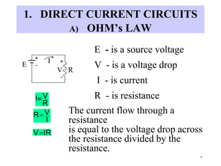
- 1. 6 1. DIRECT CURRENT CIRCUITS A) OHM’s LAW + - - + E I V R E - is a source voltage V - is a voltage drop I - is current R - is resistance The current flow through a resistance is equal to the voltage drop across the resistance divided by the resistance. R VI I VR IRV
- 2. 7 B) POWER DISSIPATED IN A RESISTANCE + - - + 312V e.g. 12V Watts Second Joules Second Coulomb Coulomb JoulesVIP IRV R2IIIRP Watts also I V R P V V R V R 2 Watts 4A 3 12I Watts48 3 212324412P
- 3. March, 1998 (R-?) vol10/auth/bb/intr/sf/22103/wc/electricity.ppt 8 C) KIRCHHOFF’S VOLTAGE LAW (KVL) In a series circuit the current is common to all the elements in series. KVL - The sum of the voltage drops around a closed electric circuit is equal to the source voltage. + - + - + - + - +- E I R1 R2 V3 E q u a t i o n 4 R 3 R 2 R 1 R T R T IR) 4 R 3 R 2 R 1 I(RE 4 IR 4 V, 3 IR 3 ,V 2 IR 2 V, 1 IR 1 V 4 V 3 V 2 V 1 VE V1 V2 V4 R4 R3
- 4. 9 I V1 V2 + -24V 2 3 7 V3 Volts1472 3 V Volts632 2 V Volts422 1 V A224/12I 12732 T R
- 5. 10 Watts4828128 3 P 2 P 1 P T P Watts28 2 7 14722142 3 P Watts12 2 3 632262 2 P Watts8 2 2 422242 1 P P source = 24 X 2 = 48 Watts
- 6. 11 D) KIRCHHOFF’S CURRENT LAW (KCL) + - + - + - IT E V R1 R2 R3 I1 I2 I3 V V In a parallel circuit the voltage is common to all elements in parallel. 3 R 1 2 R 1 1 R 1 V 3 R V 2 R V 1 R V 3 I 2 I 1 I T I 3 R V 3 I, 2 R V 2 I, 1 R V 1 I
- 7. 12 KCL-The current flow towards a point is equal to the current flow away from the point. R T V I T 1 R1 1 R2 1 R3 1 2 Resistors in Parallel R1 R2 1
- 8. 13 IT 3A 4 12 3 I2A, 6 12 2 I4A, 3 12 1 I IT=4+2+3=9A P1=12 x 4 = 48 W P2= 12 x 2=24 W P3= 12 x 3=36 W PT=48+24+36=108 W P source = 12 x 9=108 W 3 4 T R 3 4 9A 12V T R 4 1 6 1 3 1 1OR e.g. 12V I1 I2 I3 3 6 4
- 9. 14 Current (milliamps) Effects 0 to 2 Threshold of sensation 3 to 8 Mild to painful sensation 9 to 19 Can not release grip due to muscular contraction 20 to 69 Severe shock and risk of breathing difficulties Over 70 Risk of death from ventricular fibrillation 200 Risk of exit and entry point burns along with severe burns to the skin Source: Canadian Occupational Safety, January/February 1988 Effects of Electricity
- 10. 15 2. A.C. CIRCUITS A) SINUSOIDAL VOLTAGE AND CURRENT v +A -A t SINE FUNCTION A = AMPLITUDE w = 2pf RADIANS/SECOND v = A sin w t 0
- 11. 16 COSINE FUNCTION v -A A t v = A cos w t t v v=A sin w t v=A cos w t
- 12. 17 B) ROOT MEAN SQUARE (RMS) VALUE The use of RMS values allows one to analyze an A.C. circuit as if it were a D.C. circuit. + - D.C. CIRCUIT A.C. CIRCUIT I i E V R v=f(t) v R
- 14. 19 MAGNETIC FLUX & INDUCTANCE L - Henries I - Amperes N - Turns - Webers The voltage induced in a coil is due to the time rate of change of flux encircled by the coil. e = N * d /dt. But the flux is produced by the current in the coil. Therefore e = L*di/dt = N * d /dt or Li = N. L = N / I
- 15. 20 Magnetic Flux In A Coil
- 16. 21 INDUCED VOLTAGE BY A MOVING MAGNETIC FIELD
- 17. 22 VOLTAGE INDUCED IN A COIL
- 19. 24 MOTOR ACTION
- 21. 26 INDUCED VOLTAGE IN A ROTATING COIL
- 22. 27 INDUCED VOLTAGE IN A ROTATING COIL
- 23. 28 INDUCED VOLTAGE BY ROTATING FIELD
- 24. 29 3 PHASE AC GENERATOR
- 25. 30 AC GENERATOR WITH IMBEDDED WINDINGS CLof Stator & Rotor Voltage E being induced in stator conductors FluxRotor Conductors Rotor Direction of Rotation of Rotor F
- 26. 31 C) INDUCTIVE REACTANCE i vL L fLj2Lj A 2 2 LAj L I L V j L X REACTANCEINDUCTIVE 2 A L I, 2 LA L tLAcos dt diL L v,tAcos dt di tsinAi, dt diL L v v pw w w wwww w Current lags voltage by 900
- 27. 32 C) POWER IN AN INDUCTANCE v L i v L di dt -jQL v i v i VOLTAGE AND CURRENT WAVEFORMS t v i p i p v POWER WAVEFORM Vars L X 2jV L X2jIIjV L Q t Inductive Reactive Power is used by Motors, Transmission Lines, Transformers
- 28. March, 1998 (R-?) vol10/auth/bb/intr/sf/22103/wc/electricity.ppt 33 CAPACITOR
- 30. 35 B) POWER IN A CAPACITANCE v C jQc dt dvCi t v,i v i 90o VOLTAGE AND CURRENT WAVEFORMS o t POWER WAVEFORM + - v i p P v i Vars C X 2Vj C X2jIIjV C Q Capacitive Reactive Power is used by Capacitors, Transmission Lines.
- 31. 36 E) PHASORS PHASORS ARE OF THE FORM a+jb +j (a+jb) (a-jb)-j a a + jb represents the addition of two vectors at right angles. 2b2ajba The angle that a + jb is tan-1 a b 2b2ajba tan-1 a b similarly 2b2ajb-a tan -1 a b-
- 32. March, 1998 (R-?) vol10/auth/bb/intr/sf/22103/wc/electricity.ppt 37 When solving for currents and voltages in A.C. circuits use is made of complex numbers. When a resistance is added to a reactance the resultant is called impedance. (3+j4) e.g. 53.13 , 5 2423 j43 L XR j4 L X3R tan -1 3 4
- 33. 38 F) RLC IN SERIES 120V R jwL V -j/wC -j12 j20 j8 5 5 8 ,, 12.73A 589.43 120I 589.43 1tan6425 j85 j12j205Z j12 C Xj20 L X5R the current is 12.73A and it lags the voltage by 58o.
- 35. 40 G) RLC IN PARALLEL IT IR IL IC 120V j40j306 j3 -j4 20A 120V 2.865.99 2.8620.02 120 A2.8620.02 20 11 tan1400 j120 j3j420 T I j3 j40 120 C I j4A j30 120 L I 20A 6 120 R I Z the total current is 20.02 A and it lags the voltage by 2.86o. -j1
- 39. 44 3. POWER & POWER FACTOR A) POWER IN A RESISTIVE CIRCUIT E R i i v R P v,i i v TIME p,v, i P TIMEv i AVERAGE VALUE OF POWER=P WattsR2I R 2VIV R P Active, True, Real Power is supplied by the Turbine. The Generator converts Mechanical Power into Electrical Power. True Power is required for Motors, Lighting & Heating.
- 40. 45 B) POWER IN A CAPACITANCE v C jQc dt dvCi t v,i v i 90o VOLTAGE AND CURRENT WAVEFORMS o t POWER WAVEFORM + - v i p P v i Vars C X 2Vj C X2jIIjV C Q Capacitive Reactive Power is used by Capacitors, Transmission Lines.
- 41. 46 C) POWER IN AN INDUCTANCE v L i v L di dt -jQL v i v i VOLTAGE AND CURRENT WAVEFORMS t v i p i p v POWER WAVEFORM Vars L X 2jV L X2jIIjV L Q t Inductive Reactive Power is used by Motors, Transmission Lines, Transformers
- 42. 47 D) POWER IN RESISTANCE & REACTANCE VOLTAGE AND CURRENT WAVEFORMS v i t v i POWER WAVEFORM v,i,p v i p t
- 44. 49 4. THREE PHASE STAR CONNECTION A) CURRENT IN STAR CONNECTION RED PHASE CURRENT IR RED PHASE WINDING R IR RED PHASE WHITE PHASEWHITE PHASE WHITE PHASE CURRENT IW BLUE PHASE R BLUE PHASE IB BLUE PHASE CURRENT IB IW R 3 PHASE GENERATOR OR SOURCE 3 PHASE LOAD
- 45. 50 WAVEFORMS OF BALANCED CURRENTS +Im -Im -.5 Im .866 Im .5 Im .866Im iR iW iB t t1 t2 t3
- 46. 51 RED PHASE WHITE PHASE NEUTRAL WIRE BLUE PHASE R1 R2 R3 iR=Imax iW=.5 Imax iB=.5 Imax iN=-IR +.5 Iw+.5 IB STAR SOURCE USING 4 WIRES TO SUPPLY A BALANCED THREE PHASE LOAD, AT TIME t1 IN= 0
- 47. 52 R N B W B W N RIR R1 R2 R3 IB IW IR IW IB LOAD A) THREE PHASE 3 WIRE STAR SYSTEM ILINE = IPHASE SOURCE
- 48. 53 B) VOLTAGES IN STAR CIRCUITS V = VNR N V = VNW V = VNB VBR=VLINE = VNB -VNR R W B
- 50. 55 5. THREE PHASE DELTA CONNECTION A) CONNECTION BLUE PHASE WHITE PHASE RED PHASE BLUE PHASE RED PHASE WHITE PHASE SOURCE LOAD
- 51. 56 B) WAVEFORM OF VOLTAGES GENERATED IN THE DELTA CONNECTED WINDINGS TIME Vr Vw Vb t1 t2
- 52. 57 C) PHASE AND LINE VOLTAGE R B W V PHASE V PHASE V PHASE B R W V LINE V LINE V LINE V PHASE =VLINE
- 53. 58 D) CURRENTS IN A DELTA SYSTEM IB IW IR R W B W B R SOURCE LOAD IR IW IB
- 54. 59 PHASE AND LINE CURRENTS IN A DELTA -IW IW IR -IR IB -IB 30o 30o 30o IR IB IW haseI3I pLine
- 55. 60 6. POWER IN THREE PHASE CIRCUITS A) POWER IN A STAR CONNECTION 2 T Q2 T P T U V.A. L I L V3 T U Varssin L I L V3 T Q WATTScos L I L V3 T Pcos L I. 3 L V 3. T P 3 L V V, L II cosI3V T PcosIVP , , QT PT UT
- 56. 61 B) POWER IN A DELTA CONNECTION V.A. ,. I , 2 T Q2 T P L I L .V3 T U Varssin L I L .V3 T Q WATTScos L I L V3 T Pcos 3 L I L 3.V T P 3 L I cosI3V T PcosIVP PT UT QT
- 57. 62 MACHINE INSULATION FAILURE EXCESSIVE MOISTURE & HEAT •MOISTURE WILL SEEP INTO THE HAIRLINE CRACKS OFAGING INSULATION AND CREATE SHORT CIRCUIT BETWEEN WINDINGS CAUSING SEVERE DAMAGE. •TRANSFORMER OIL MUST BE KEPT DRY TO MAINTAIN ITS INSULATION STRENGTH. •PROLONGED HIGH TEMPERATURE OPERATION CAUSES INSULATION TO BECOME BRITTLE AND CRACK & MOISTURE PENETRATION RESULTS OR PHYSICAL CONTACT BETWEEN CONDUCTORS. •CHEMICALAGING OF OIL OCCURS RAPIDLY AT HIGH TEMPERATURES. A DAILY RECORD OF THE OPERATING TEMPERATURES IS MAINTAINED.